

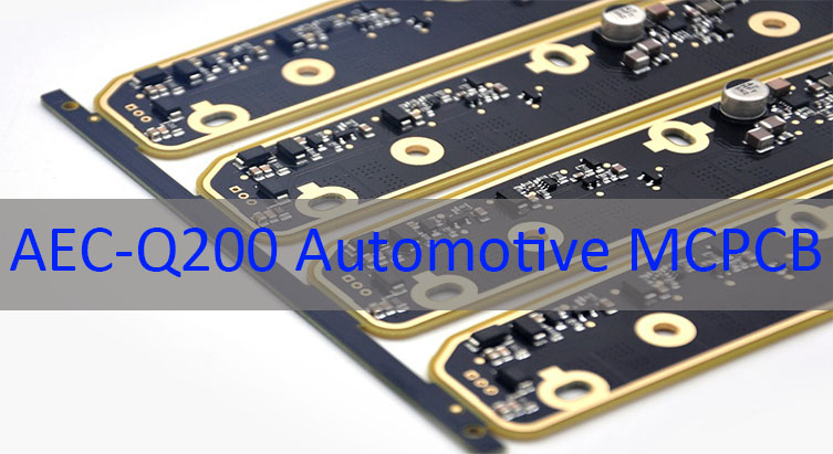
AEC-Q200 automotive MCPCB refers to metal core printed circuit boards built with components that meet the AEC-Q200 stress test qualification for passive automotive electronics, ensuring stable performance under extreme temperature, vibration, and humidity. This article explains what this qualification means, why it matters for reliability, and how to design, select components, and validate these boards for automotive applications.
Are you facing these common challenges when working with automotive MCPCBs?
- Sourcing AEC-Q200 qualified components that are actually in stock and traceable.
- Managing thermal runaway risks in high-power LED or power module designs.
- Avoiding layout errors that violate creepage/clearance rules in high-voltage zones.
- Misjudging component placement impacts on thermal resistance and signal integrity.
- Passing system-level validation without costly redesign loops.
At EBest Circuit (Best Technology), we address these pain points with proven, production-ready solutions:
- Provide verified AEC-Q200 components for automotive MCPCB from trusted franchised sources.
- Optimize MCPCB stack-up and copper layouts for efficient heat dissipation paths.
- Apply automotive-grade spacing rules and insulation materials per HV requirements.
- Use thermal simulation to guide AEC-Q200 compliant component placement strategy.
- Deliver full system-level testing reports including thermal cycling and vibration.
EBest Circuit (Best Technology) is a professional PCB manufacturer specializing in automotive MCPCB design with AEC-Q200 passives and full turnkey assembly. With ISO/TS 16949 certification and deep experience in automotive lighting, EV control modules, and ADAS systems, we ensure every board meets strict reliability and traceability standards. We’re happy to provide technical support and personalized quotes, and you can reach us at sales@bestpcbs.com.
What Is AEC-Q200 Automotive MCPCB Meaning?
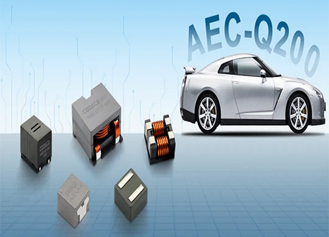
An AEC-Q200 automotive MCPCB integrates passive components (resistors, capacitors, inductors) that have passed the AEC-Q200 qualification—a rigorous set of stress tests defined by the Automotive Electronics Council. These tests include high-temperature endurance, mechanical shock, moisture resistance, and solder heat exposure. When combined with a metal core PCB (MCPCB) designed for thermal management, the result is a board engineered for guaranteed reliability in harsh automotive environments such as engine compartments, headlamp assemblies, and battery management systems.
| Key Element | Description |
|---|---|
| AEC-Q200 | Passive component qualification standard for automotive reliability |
| MCPCB | Metal Core PCB for superior heat dissipation |
| Combined Value | Stable operation under vibration, heat, and humidity |
What Reliability Metrics Actually Matter in AEC-Q200 Automotive MCPCB Design?
Reliability in automotive MCPCB with AEC-Q200 compliant components is measured by metrics that reflect real-world stress conditions. The most critical include:
- Thermal Cycling Endurance – Ability to survive −40°C to +125°C cycles without delamination.
- High-Temperature Operating Life (HTOL) – Long-term stability at max junction temperature.
- Moisture Sensitivity Level (MSL) – Resistance to popcorn cracking during reflow.
- Vibration & Mechanical Shock – Structural integrity under road conditions.
- Dielectric Withstand Voltage – Insulation strength for high-voltage isolation.
These metrics ensure the AEC-Q200 qualified components in automotive MCPCB assembly perform consistently over a vehicle’s lifespan.
How to Calculate Thermal Resistance Path in Automotive MCPCB with AEC-Q200 Components?
Thermal resistance (θJA) is calculated as:
θJA = θJC + θCS + θSA
Where:
- θJC = Junction-to-case resistance of the component
- θCS = Case-to-sink (thermal interface material)
- θSA = Sink-to-ambient (MCPCB metal core to air)
Using AEC-Q200 components for automotive MCPCB, designers must account for:
- Copper thickness and layout
- Dielectric layer thermal conductivity
- Metal core material (Aluminum vs. Copper)
| Parameter | Typical Value | Impact |
|---|---|---|
| MCPCB Dielectric k | 1.0–3.0 W/m·K | Higher k reduces θCS |
| Copper Thickness | 1–3 oz | Improves lateral heat spreading |
| Metal Core | Al 5052 / Cu | Cu offers lower θSA |
Optimizing this path ensures guaranteed reliability under continuous load.
How Does AEC-Q200 Qualification Impact Component Placement Strategy on MCPCB?
AEC-Q200 compliance influences placement through:
- Thermal Proximity Rules – Keep high-dissipation parts near metal core vias.
- Stress-Sensitive Zones – Avoid edges prone to vibration-induced fatigue.
- Symmetry for Thermal Balance – Distribute heat sources evenly.
- Clearance for Rework – Ensure access without damaging adjacent passives.
- Signal Integrity Considerations – Minimize loop areas for noise-sensitive circuits.
Proper placement of AEC-Q200 components for automotive MCPCB reduces hotspots and improves long-term durability.
How to Design Creepage and Clearance for High-Voltage Automotive MCPCB Applications?
For high-voltage designs (e.g., EV inverters, OBCs), creepage and clearance must comply with IEC 60664 and automotive standards:
| Voltage (V) | Pollution Degree 2 Creepage (mm) | Clearance (mm) |
|---|---|---|
| 48V | 1.5 | 1.0 |
| 400V | 8.0 | 5.5 |
| 800V | 12.5 | 8.0 |
Design tips:
- Use automotive MCPCB design with AEC-Q200 passives rated for higher voltage classes.
- Apply conformal coating or slotting to increase creepage.
- Select components with extended terminal spacing.
This prevents arcing and ensures AEC-Q200 qualified components in automotive MCPCB assembly remain safe under humidity and contamination.
How to Select AEC-Q200 Compliant Components for Automotive MCPCB BOM Optimization?
BOM optimization requires balancing cost, availability, and reliability:
- Verify AEC-Q200 Status – Check manufacturer datasheets and PPAP documentation.
- Prioritize Multi-Source Parts – Reduce supply risk.
- Match Temperature Ratings – Use Grade 0 (−40°C to +150°C) for under-hood.
- Consider Footprint Compatibility – Enable second-source substitution.
- Evaluate Lifetime Availability – Avoid NRND (Not Recommended for New Designs).
Selecting automotive MCPCB with AEC-Q200 compliant components from the start avoids late-stage redesigns.
How to Validate AEC-Q200 Automotive MCPCB Through System-Level Testing?
Validation goes beyond component-level checks:
| Test Type | Purpose |
|---|---|
| Thermal Shock | Detect solder joint fatigue |
| Vibration (Random/Harmonic) | Simulate road conditions |
| Humidity Bias Test | Assess corrosion resistance |
| Power Cycling | Verify thermal expansion tolerance |
| EMC Pre-Scan | Ensure electromagnetic compatibility |
System-level validation confirms that the AEC-Q200 automotive MCPCB performs reliably in the actual vehicle environment.
To sum up, AEC-Q200 automotive MCPCB delivers guaranteed reliability by combining thermally optimized metal core boards with rigorously tested passive components. This article covered the meaning of AEC-Q200, key reliability metrics, thermal and placement strategies, high-voltage design rules, component selection, and system-level validation methods.
EBest Circuit (Best Technology) specializes in automotive MCPCB design with AEC-Q200 passives, offering full engineering support from schematic review to final assembly. We help customers avoid common pitfalls and achieve first-pass success in demanding automotive applications. Pls feel free to contact our team today at sales@bestpcbs.com to discuss your next AEC-Q200 qualified automotive MCPCB project.
FAQs About AEC-Q200 Automotive MCPCB
Q: Is AEC-Q200 mandatory for all automotive MCPCBs?
A: It is mandatory for passive components in safety- or mission-critical systems.
Q: Can non-AEC-Q200 parts be used in automotive MCPCBs?
A: Only in non-critical functions, but this increases risk and may violate OEM requirements.
Q: Does AEC-Q200 apply to active components?
A: No—active ICs follow AEC-Q100; AEC-Q200 covers passives only.