What is copper coated PCB board? Let’s explore its meaning, benefits, applications, design guide and consideration, production process through this blog.
Are you worried about these problems?
Copper Oxidation in Standard PCBs: How to ensure long-term conductivity stability?
High-Frequency Signal Loss: How to enhance copper foil adhesion and reduce impedance?
High Cost for Small-Batch Customization: Can cost-effectiveness and fast delivery coexist?
As a copper coated PCB manufacturer, EBest Circuit (Best Technology) can provide service and solutions:
Anti-Oxidation Copper Coating: Nano-scale sealing process improves oxidation resistance by 300%, with conductivity decay <2% over 5 years.
Dynamic Lamination Technology: Gradient temperature control achieves 1.5N/mm² copper-to-substrate adhesion, reducing high-frequency signal loss by 40%.
Flexible Supply Chain: 24 hours rapid prototyping + tiered pricing model; minimum order quantity reduced by 60% to 10㎡ compared with industry standard.
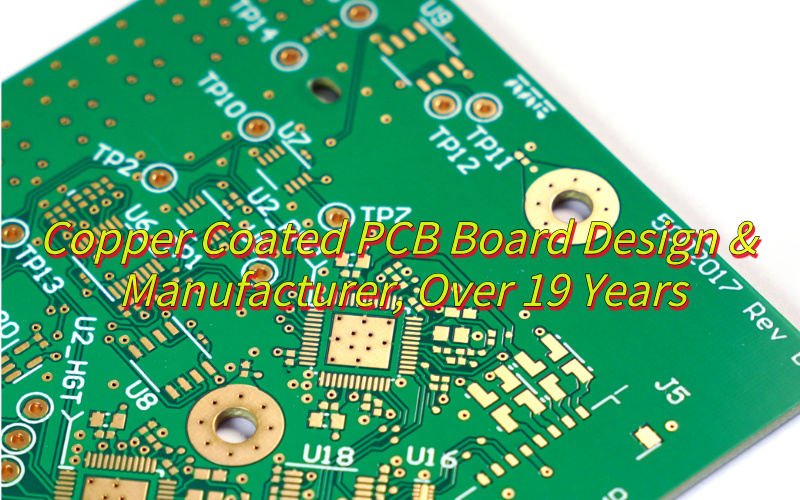
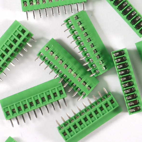
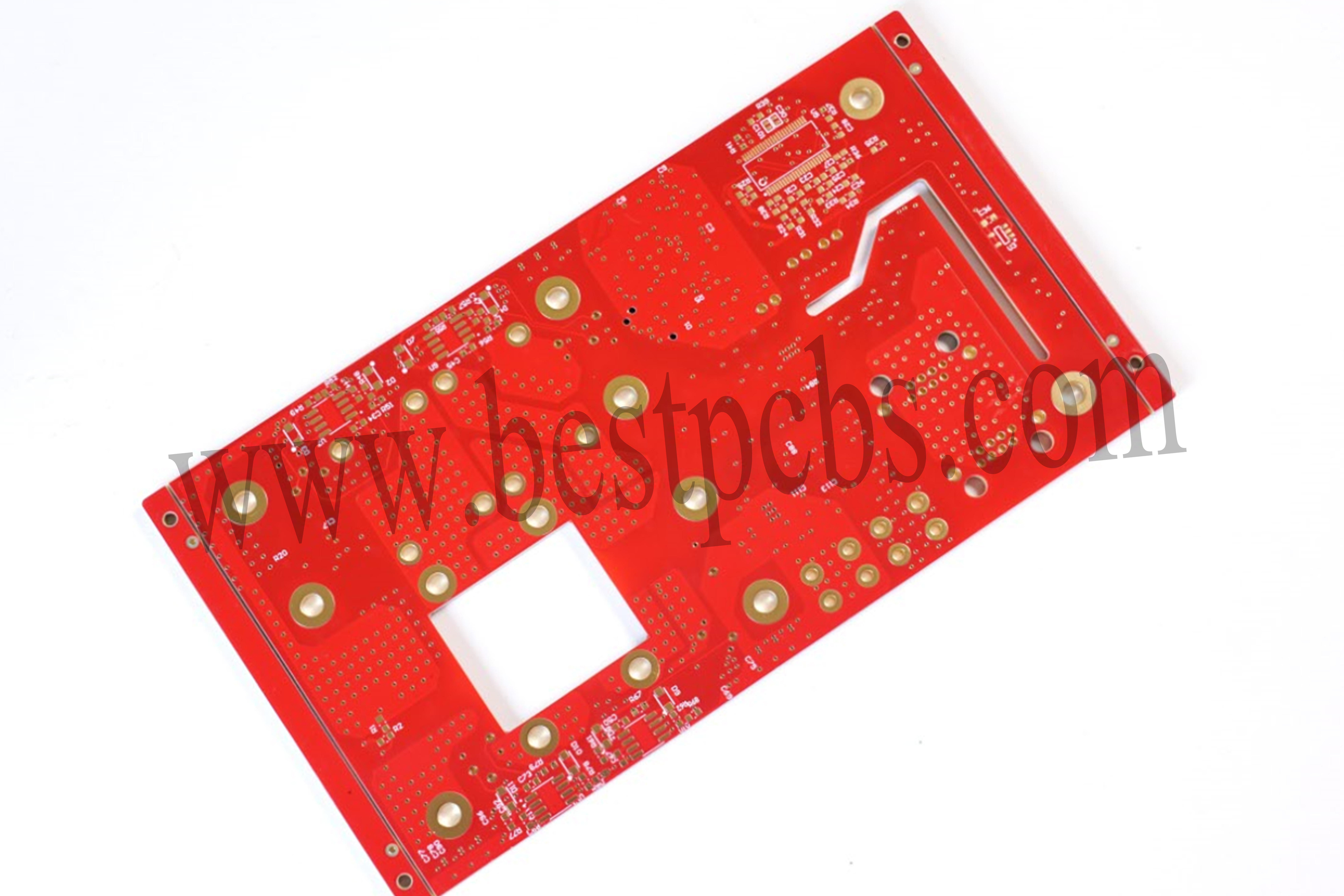
A Copper Coated PCB Board is a printed circuit board where a uniform copper layer, typically 17 to 105 micrometers thick, is applied to the surface of an insulating substrate. This copper layer forms conductive pathways for transmitting electronic signals, distributing power, and dissipating heat. Manufactured through precision processes like etching, drilling, and plating, the copper adheres firmly to the substrate, ensuring high electrical conductivity, thermal conductivity, and mechanical strength.
What Are Advantages of Copper Coated PCB?
High-fidelity signal transmission: Ultra-high electrical conductivity minimizes signal attenuation, enabling precise signal routing in high-frequency/high-speed designs while reducing EMI and crosstalk.
Enhanced thermal management efficiency: High thermal conductivity (380-401 W/(m·K)) achieves efficient heat dissipation without requiring additional cooling modules, extending device lifespan and mitigating thermal failure risks.
Robust mechanical reliability: Strong peel strength (≥1.4 N/cm) ensures secure bonding between copper layers and substrates, withstanding harsh environmental stresses like industrial vibration and automotive impacts.
Expanded design freedom: Supports fine-line processes (line width/spacing ≤50μm) to meet miniaturization demands in consumer electronics and 5G devices, enabling higher routing density and space utilization.
Optimized cost efficiency: Copper’s cost advantage (1/100 of silver, 1/1000 of gold) combined with mature plating/etching processes balances BOM costs while ensuring stable mass production supply.
Broad process compatibility: Adapts to diverse substrates (FR-4, ceramic, metal-based) and surface treatments (OSP/ENIG), compatible with lead-free soldering and seamless multi-scenario application.
Strengthened EMI shielding: Natural copper shielding effect reduces external interference, ideal for sensitive equipment like medical and aerospace systems requiring ultra-stable signal performance.
Outstanding environmental compliance: Meets RoHS/REACH standards with >95% copper recovery rate, lowering waste disposal costs and enhancing sustainability credentials.
What Are Applications of Copper Coated PCB Board?
5G base station antenna board
Data center server backplane
Electric vehicle inverter module
Supercharging pile power distribution board
Deep space probe control board
Downhole high-temperature sensing circuit
Hydrogen fuel cell stack bipolar plate
Solid-state battery lithium metal deposition substrate
Match copper thickness to actual current needs: use 0.5oz (18μm) for RF circuits ≤3A/mm² and 2oz (70μm) for high-temperature zones like automotive ECUs. Localized thickening saves 20-30% copper costs while maintaining conductivity.
2. Cost-Effective Surface Finishes
Choose between low-cost HASL (100-500μm, 40-60% cheaper than ENIG) for consumer electronics and high-performance ENIG (2-6μm gold, 99.9% purity) for 5G/high-frequency areas.
3. Layout Optimization for Material Efficiency
Achieve ≥85% material utilization through compact routing. Replace 90° traces with 45° angles to reduce etching defects and signal loss. Use buried vias instead of through-holes to cut drilling costs by 30%.
4. DFM Rules for Manufacturing Yield
Standardize trace width/spacing ≥50μm for conventional processes and ≥30μm for HDI. Enforce 3W rule (minimum spacing ≥3× line width) to prevent shorts, reducing defect rates by 50%. Avoid sharp angles ≥90° to minimize etching errors.
5. Balanced Substrate and Layer Count
Use FR-4 for digital circuits ($0.5/㎡) and high-speed materials like FR-408 only where necessary. Reduce layer count from 6 to 4 layers through optimized ground plane partitioning, saving 25% lamination costs while maintaining signal integrity.
6. Panelization and Process Scaling
Maximize panel utilization to ≥90% using V-cut or tab routing. For small boards, adopt 2×2/3×3 matrix paneling to reduce per-unit costs by 10-15%. Source locally to cut logistics costs by 20%.
7. Targeted Testing and Validation
Use flying probe testing for small batches, saving 30% on fixtures. Limit impedance testing to high-frequency zones. Pre-validate designs with tools like Altium/Cadence to reduce prototype iterations and rework costs by 40%.
8. Standardization and Modular Design
Build libraries of standard footprints and routing rules to cut design time by 30%. Reuse modules (power/interface blocks) to reduce NRE costs by 25%. Collaborate with manufacturers on process parameters like etch times and lamination temperatures.
How to Make Copper Coated on PCB Board?
1. Pre-Cleaning & Surface Preparation
Deburring: Remove drilling residues/mechanical burrs using abrasive brushes or chemical agents.
Alkaline Degreasing: Immerse PCB in alkaline solution (e.g., NaOH) to eliminate oils, fingerprints, and oxides.
Desmear: Apply potassium permanganate (KMnO₄) to etch epoxy resin residues from hole walls, enhancing surface adhesion.
Micro-Etching: Use sulfuric acid/hydrogen peroxide (H₂SO₄ + H₂O₂) to create micro-roughness (5-15μin Ra) for optimal copper adhesion.
2. Electroless Copper Plating (Seed Layer)
Activation: Coat hole walls/PCB surface with palladium (Pd) catalyst via immersion in Pd-Sn colloid solution.
Chemical Bath: Submerge PCB in alkaline copper bath (CuSO₄ + formaldehyde/reducing agent) at 50-70°C for 15-30 min.
Deposition: A uniform 0.2-0.8μm copper layer forms through redox reaction, enabling electrical conductivity for through-holes.
19-Year Copper Plating Expertise: Leveraging 19 years of specialized copper plating technology, we achieve 0.2mm fine-line processing and ±10% hole copper thickness uniformity control, reducing rework costs caused by process defects.
Customized Multi-Type Copper Plating: Offering chemical plating, electroplating, pulse plating, and other processes tailored to scenarios like EV chargers and solar inverters, enhancing product performance compatibility.
24-Hour Rapid Prototyping: Utilizing MES intelligent systems and local supply chains to deliver prototypes within 24 hours, accelerating R&D cycles and market entry.
Transparent Full-Process Quality Control: Adhering to IPC Class 2 standards with 36 inspection steps (including X-ray copper thickness testing and 100A load aging tests), ensuring batch-level quality traceability and stable delivery performance.
100% Batch Inspection Guarantee: Implementing full-batch inspection with SPC statistical control and 8D problem-solving, preventing bulk defects and minimizing after-sales risks.
Thick Copper Foil Thermal Optimization: Using ≥2oz thick copper foil and 8W/(m·K) thermal conductivity embedded blocks to cut DC resistance by 50% and outperform industry-standard temperature rise control, ensuring reliable high-power operation.
Multi-Layer Copper Design Flexibility: Supporting 12-layer thick copper stack-ups and stepped copper layer designs (e.g., 3oz outer/2oz inner layers) for specialized needs like BMS systems and 5G base stations, optimizing space utilization and electrical performance.
Welcome to contact us if you have any request for copper coated PCB:sales@bestpcbs.com.
PCB in manufacturing plays a critical role in today’s electronic industry. This blog provides a comprehensive guide to PCB manufacturing, covering materials, technologies, machinery, step-by-step production processes, testing methods, and practical tips for selecting and sourcing reliable PCB manufacturers in China.
Are you facing any of the following challenges when looking for a reliable PCB manufacturer?
Attractive low quotes, but inconsistent quality leads to rework or scrap.
Poor communication with suppliers, making design or production issues hard to resolve promptly.
Insufficient technical support, making complex boards or high-frequency PCBs difficult to produce.
Lack of transparency in materials, processes, and testing, making it hard to control total cost of ownership (TCO).
High risk when placing large orders without verifying quality and lead times first.
Here’s how EBest Circuit (Best Technology) addresses these common challenges:
Transparent and reasonable quotes that cover high-quality materials, complete processes, thorough testing, and reliable service to ensure long-term stability.
Dedicated project managers provide full-process support and English communication, proactively giving DFM feedback and optimization suggestions.
Technical expertise and design support for high-frequency, HDI, blind/buried vias, and other complex PCB manufacturing.
Full transparency in materials, processes, and test reports, allowing customers to control TCO and make informed decisions.
Support for small-batch sample validation and third-party testing, allowing gradual scale-up to full production with minimal risk.
Printed Circuit Board, or PCB, is the backbone of modern electronics. When people ask what PCB stands for, the answer is straightforward—Printed Circuit Board. But in manufacturing, it means much more than just a name. It is the essential platform that connects and supports components in nearly every electronic product we use today. Without PCBs, manufacturing electronics would still rely on bulky wiring and manual assembly, which is slow, costly, and unreliable.
Understanding PCBs in Simple Terms
In the simplest sense, a PCB is a thin board made from insulating materials, usually fiberglass or ceramic, with copper layers that form conductive pathways. These copper tracks replace the need for traditional wiring. Components like resistors, capacitors, and chips are mounted directly on the board, and the copper routes connect them into a functioning system.
This simplicity is the reason why PCBs became so popular. They make electronic designs smaller, lighter, and more efficient. That is why you can hold a smartphone in one hand instead of carrying a box full of circuits and wires.
The Key Types of PCBs in Manufacturing
In manufacturing, PCBs are not one-size-fits-all. They come in different structures to serve different needs. Generally, there are three primary types:
Single-sided PCBs – They have copper traces on one side only. Simple and cost-effective, used in calculators, LED lights, and low-complexity devices.
Double-sided PCBs – Copper patterns exist on both sides, connected by vias. They support more components in a compact size, common in control systems and consumer electronics.
Multilayer PCBs – These are stacks of multiple copper and insulating layers, laminated together. They handle complex, high-speed, and high-density designs used in servers, medical devices, and aerospace systems.
This variety shows how PCBs can adapt to both simple gadgets and cutting-edge equipment.
Why PCBs Became the Standard in Manufacturing
The widespread adoption of PCBs in manufacturing was not accidental. There are at least four strong reasons:
Miniaturization: They reduced the size of electronic products dramatically.
Reliability: Consistent copper pathways mean fewer connection failures compared to hand-soldered wiring.
Mass Production: PCBs can be produced in bulk with high accuracy, lowering costs.
Design Flexibility: Engineers can create intricate circuits that would be impossible with loose wires.
These advantages explain why PCBs moved from laboratories into mass production and became a universal standard.
Everyday Products That Contain PCBs
It’s hard to name a modern product without a PCB inside. Consumer electronics such as smartphones, laptops, and TVs all rely on them. Cars use them for engine control, safety systems, and infotainment units. Medical equipment, from diagnostic tools to life-support systems, depends on PCB reliability. Even household appliances like washing machines and microwaves contain small but critical boards.
This universal presence highlights the importance of PCBs in manufacturing—no matter if the device is simple or complex, a PCB is likely powering it.
Why PCBs Matter in Manufacturing
To sum up, PCB in manufacturing is not just a circuit board; it is the foundation of modern electronic innovation. From single-sided boards in basic products to multilayer structures in advanced systems, PCBs make production practical, scalable, and reliable. They replaced traditional wiring with something faster, more compact, and easier to reproduce. Their popularity lies in simplicity, flexibility, and the ability to serve almost every industry.
Electronics without PCBs would still be large, fragile, and inconsistent. With them, manufacturers create everything from affordable gadgets to mission-critical aerospace systems. This is why PCBs are the true silent force behind our connected world.
What are the Technologies Used in PCB Manufacturing?
Modern PCB fabrication has advanced far beyond simple copper patterning. Today, manufacturers leverage a suite of cutting-edge technologies to meet the demands of high-density, high-speed, and high-reliability electronic systems.
1. Photolithography and Laser Direct Imaging (LDI)
Photolithography remains a cornerstone in PCB production. It transfers circuit patterns from CAD files to copper-clad laminates using UV light and photoresist. To achieve finer lines and spaces for high-density interconnect (HDI) boards, laser direct imaging (LDI) is increasingly employed. LDI provides superior precision, reduces alignment errors, and shortens production cycles, particularly for line widths below 50 μm, which is critical for HDI/BUM and chip-scale packaging PCBs.
2. Microvia and Laser Drilling Technologies
The trend toward smaller vias is driven by the integration density of modern ICs. Mechanical drilling has limits, typically above 100 μm. For microvias and blind/embedded vias, CO₂ and UV laser drilling are widely used. UV lasers can create vias smaller than 50 μm with minimal thermal damage, while CO₂ lasers are effective for slightly larger microvias and high-throughput production. Hybrid laser systems combine the advantages of both to improve efficiency and accuracy.
3. High-Density Multilayer Lamination
As IC complexity grows, PCBs have evolved from simple single-layer boards to multilayer HDI structures. Modern lamination integrates multiple copper-clad laminates, often using sequential lamination for buried and blind vias. Layer-to-layer registration precision has become crucial, with tolerances controlled to a few microns to ensure signal integrity and reliable interconnects. Advanced dielectric materials with low coefficient of thermal expansion (CTE) and tailored Tg values help maintain layer alignment under thermal stress.
4. Fine Line and Conductor Technology
Conductor miniaturization is essential for high-speed and high-frequency designs. Line widths have evolved from 100 μm to as narrow as 8–10 μm. Achieving such precision requires ultra-thin copper foils, improved etching techniques, and strict surface treatments. Uniform copper distribution, high-resolution photoresists, and vacuum or rapid etching systems ensure line width tolerance and prevent defects such as over-etching or rough edges, which can cause signal degradation.
5. Surface Finish and Pad Coating Technologies
Surface finishing technologies ensure solderability and long-term reliability of PCBs. Traditional HASL (Hot Air Solder Leveling) has given way to more precise techniques like OSP (Organic Solderability Preservatives), chemical Ni/Au, and Pd/Au coatings. These coatings protect copper pads from oxidation, provide flat surfaces for fine-pitch SMT assembly, and enable high-temperature soldering required for lead-free processes. Pd and Au layers also support wire bonding and fine-pitch connections.
6. Advanced CCL Materials
Copper-clad laminate (CCL) materials have evolved to support HDI and high-performance applications. High Tg, low CTE, and uniform dielectric layers help manage thermal expansion and prevent CAF (Conductive Anodic Filament) formation. Special CCLs, including flat E-glass fabrics and metal-core laminates, improve laser drilling performance, reduce surface roughness, and support high-density fine-line PCB fabrication. Low and high dielectric constants are tailored for RF/microwave applications and embedded passive components.
7. Automation and Robotics in PCB Manufacturing
Automation plays a critical role in modern PCB production. Automated assembly lines, robotic drilling, and pick-and-place machines ensure consistent quality and reduce human error. High-density SMT assembly, precise component placement, and in-line inspection systems allow manufacturers to handle complex boards efficiently while meeting tight tolerances for HDI and multilayer PCBs.
8. Trends Driving PCB Technology
PCB technology development is closely tied to IC integration and system miniaturization. Microvia adoption, ultrafine lines, multilayer HDI structures, and embedded components address high-density requirements. Materials science advances, including high Tg, low CTE laminates, and improved surface finishes, support higher frequency, higher power, and higher reliability applications. Laser-based processes and LDI enable precise manufacturing for emerging electronics in telecommunications, aerospace, automotive, and medical devices.
What are the PCB Manufacturing Machines?
Modern PCB factories are equipped with a comprehensive set of machines, covering every stage from raw material processing to final inspection. Each machine plays a crucial role in ensuring precision, efficiency, and product reliability.
1. CNC Drilling Machines
Used to drill through-holes and vias on PCBs. CNC drilling machines provide precise control over hole size and placement, ensuring reliable interconnections for multilayer boards. Modern high-precision CNC machines can handle microvias with diameters smaller than 100 μm.
2. Laser Drilling Machines
Used for microvias and high-density boards. UV lasers can create vias smaller than 50 μm with minimal thermal damage, making them ideal for HDI and chip-scale package PCBs. CO₂ lasers are effective for slightly larger microvias and high-throughput production.
3. Imaging / LDI Machines
Include traditional photolithography and Laser Direct Imaging (LDI) systems that transfer circuit patterns to copper-clad laminates. LDI offers higher precision and is particularly suited for ultrafine lines and high-density interconnect boards.
4. Etching Machines
Remove excess copper to reveal the circuit pattern. Modern etching machines use chemical or vacuum etching to maintain line width tolerance, prevent over-etching, and ensure smooth edges, which is critical for high-speed signal integrity.
5. Solder Paste Printers
Accurately apply solder paste to PCB pads for SMT assembly. High-precision printers can handle ultra-fine pitch components, as small as 0.3 mm.
6. Dispensing Machines
Apply localized coatings such as protective varnish, conductive adhesives, or thermal interface materials (TIM) to specific PCB areas to enhance reliability.
7. Pick-and-Place Machines
Rapidly and precisely place SMD components on the PCB, forming the core of modern SMT production lines.
8. Reflow Ovens
Used to solder SMD components by melting solder paste uniformly and cooling it properly, ensuring strong and reliable joints.
9. Wave Soldering Machines
Mainly used for through-hole components, especially in mixed-technology boards that combine SMT and PTH components.
10. Automated Optical Inspection (AOI) Machines
Detect defects such as opens, shorts, misaligned components, or solder issues to improve yield and product quality.
11. Solder Paste Inspection (SPI) Machines
Check solder paste printing quality, including volume, position, and shape, to prevent placement defects in later assembly steps.
12. Flying Probe Testers
Used for small-volume or prototype PCBs to verify electrical connectivity and detect shorts without requiring a custom test fixture.
13. In-Circuit Test (ICT) Machines
Test electrical performance in mass production, verifying component placement, solder quality, and circuit integrity.
14. Surface Finish Equipment
Includes chemical Ni/Au plating, OSP, chemical Sn/Pb, and other finishes to protect pads from oxidation and ensure long-term reliability.
15. Solder Mask Printers
Apply protective coatings on PCB surfaces, preventing shorts and oxidation while leaving precise pads exposed for SMT assembly.
16. Cleaning Machines
Remove flux residues, chemical contaminants, or dust to ensure clean PCB surfaces and enhance product reliability.
AXI complements AOI by inspecting hidden joints, such as BGA or embedded components, to ensure internal soldering quality.
18. Routing, V-Cut, and Laser Cutting Machines
Separate panels into individual boards, providing smooth edges and burr-free cuts.
19. Automated Storage and Handling Systems
Connect production stages, enabling automated PCB transport, stacking, and sorting, improving overall factory efficiency.
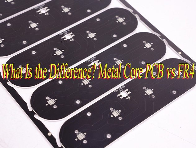
What is the Difference Between FR-4, High-Tg, and High-Frequency PCB Materials?
At EBest Circuit (Best Technology), we often get asked: “Which PCB material should I choose?” To answer this, we like to start with a simple analogy that makes the differences crystal clear.
Think of PCB materials as vehicles on a road:
FR-4 is like a family sedan. Reliable, affordable, and perfectly adequate for most everyday needs. It’s our default recommendation unless your design has special demands.
High-Tg FR-4 is like a high-performance SUV or off-road vehicle. Tougher, more heat-resistant, and designed to handle extreme environments. Ideal when your PCB faces high temperatures or long-term heavy loads, such as in automotive engine compartments or high-power power supplies.
High-frequency materials are like a race car or optical fiber. Optimized for speed and precision, minimizing signal loss. They are essential for RF, microwave, or high-speed digital circuits where signal integrity cannot be compromised.
Material Comparison Table
To help you decide, here’s a direct comparison of the key parameters:
Key Parameters
Standard FR-4
High-Tg FR-4
High-Frequency Materials
Glass Transition Temperature (Tg)
~130–140°C
>170°C
Varies, generally high
Dielectric Constant (Dk)
~4.5
~4.5
2.5–3.5 (lower and more stable)
Loss Tangent (Df)
~0.02
~0.02
<0.004 (much lower)
Material Cost
Low
Medium
High
How to Choose the Right Material?
At EBest Circuit (Best Technology), we advise our customers based on the specific environment, electrical requirements, and cost constraints.
1. When FR-4 is sufficient:
Product examples: Household electronics, toys, phone chargers, internal test boards.
Reasoning: Operating temperature is below 100°C, signal frequency is low (<1GHz), and cost is the main consideration.
2. When you must upgrade to High-Tg FR-4:
Product examples: Automotive engine control units, high-power LED lighting, high-density servers.
Reasoning: Lead-free soldering requires higher reflow temperatures. Devices may operate in high-temperature environments. Long-term reliability is critical.
3. When high-frequency materials are non-negotiable:
Product examples: 5G base station antennas, microwave and millimeter-wave devices, satellite receivers, high-speed server motherboards.
Reasoning: Extremely high operating frequencies demand excellent signal integrity and low loss. If your design reaches GHz frequencies, this is a must, not an option.
Practical Tips & Cost Considerations
Avoid over-design: Using high-frequency laminates for low-speed circuits dramatically increases cost without benefit.
Mind overall manufacturing cost: High-Tg or high-frequency materials are more expensive, and processing can be more challenging, which may increase total PCB cost.
Consult early with your manufacturer: Sharing your Gerber files and application requirements early helps EBest Circuit (Best Technology) suggest the most appropriate material, balancing performance and budget.
In a nutshell, choosing the right PCB material is like picking the right vehicle for a journey. FR-4 for everyday tasks, High-Tg FR-4 for extreme conditions, and High-Frequency materials for ultra-speed applications. At EBest Circuit (Best Technology), we act as your trusted advisor, guiding you through material selection to optimize performance, cost, and reliability.
How is a PCB Manufactured Step by Step?
At EBest Circuit (Best Technology), PCB manufacturing follows a rigorously controlled process to ensure every board meets design specifications and quality standards. Here is the step-by-step workflow for a typical four-layer PCB:
1. Material Preparation (Cutting the Base Material) We start by cutting copper-clad laminates to precise dimensions. Proper preparation ensures uniform thickness and reduces material waste during the process.
2. Inner Layer Imaging (Exposure → Development → Etching) The inner copper layers are patterned using photolithography. Engineers apply photoresist, expose the design using UV light, develop the pattern, and etch away excess copper to reveal the inner circuitry.
3. Inner Layer Inspection (AOI) Automated Optical Inspection (AOI) is performed to detect defects such as shorts, opens, or pattern misalignment. This early check prevents costly errors in subsequent steps.
4. Lamination Multiple layers are stacked and pressed together under heat and high pressure. For four-layer boards, precise layer alignment is critical to maintain electrical performance and signal integrity.
5. Drilling Holes for vias and component leads are drilled with CNC machines. At EBest Circuit (Best Technology), we use high-precision drilling to achieve exact diameter tolerances and positioning.
6. Copper Plating and Electrical Testing of the Board (Through-Hole Metallization + Panel Electric Test) Drilled holes are plated with copper to electrically connect layers. After plating, a board-level electrical test is performed to verify continuity and detect potential short circuits.
7. Outer Layer Imaging (Exposure → Development → Etching) Outer copper layers are patterned using photolithography, following the same exposure, development, and etching steps as the inner layers. This step defines the complete circuit layout.
8. Outer Layer Inspection (AOI) Another round of AOI ensures the outer layer traces are free from defects, maintaining high yield rates and reliability.
9. Solder Mask Application (Exposure → Development) A protective solder mask is applied to prevent accidental short circuits and oxidation of the copper traces. Precise mask registration is critical for fine-pitch components.
10. Silkscreen (Legend/Character Printing) Component markings, logos, and identification codes are printed on the board. This step facilitates assembly and future maintenance.
11. Pre-Baking (Drying/Board Baking) Boards undergo controlled baking to remove moisture and stabilize the material before surface finishing.
12. Surface Finishing Pads and exposed copper areas are treated with surface finishes such as HASL, ENIG, or OSP to improve solderability and protect against oxidation.
13. Board Profiling and Cutting (V-Scoring/Route Cutting) The panel is cut or scored into individual boards with precise dimensions, ensuring clean edges and proper fit in assemblies.
14. Electrical Testing (E-Test/Flying Probe) Each finished board undergoes a final electrical test to verify connectivity and functionality.
15. Final Quality Control (FQC) Boards are visually inspected and subjected to final checks to ensure they meet all design and quality requirements.
16. Packaging and Storage Completed PCBs are carefully packaged to prevent damage during transportation and stored in controlled conditions until shipment.
This workflow highlights EBest Circuit (Best Technology)’s meticulous approach to PCB manufacturing, combining advanced equipment, stringent quality control, and experienced engineering to ensure every board performs reliably in its intended application.
How to Test PCB in Manufacturing Process?
Testing is a critical step in PCB manufacturing to ensure each board’s electrical performance, physical reliability, and long-term stability. PCB testing is a multi-dimensional, staged quality assurance system, covering everything from bare boards to fully assembled products. The core process and key testing methods are summarized below.
1. Overview of the Testing Process: Four Key Stages
The PCB testing process follows a complete closed-loop workflow, allowing issues to be detected and addressed promptly:
Preparation Stage
Equipment and Program Setup: Determine the testing strategy based on PCB design requirements (layer count, trace density, functionality). Prepare the necessary testing equipment (e.g., AOI, flying probe testers, functional testers) and fixtures. Develop detailed test programs with parameters and acceptance criteria.
PCB Pre-Inspection: Conduct a visual check to ensure no mechanical damage, shorts, opens, or component misplacement/missing. For reliability tests, boards may be pre-baked to remove moisture and prevent delamination during testing.
Testing Execution Stage This stage is the core of quality control and includes multiple types of tests:
Bare Board Testing: Performed before component assembly, using flying probe or bed-of-nails testers to ensure 100% electrical connectivity with no opens or shorts.
Electrical Performance Tests: Measure insulation resistance, dielectric strength, and continuity.
Functional Testing (FCT): Simulate real operating conditions to verify full-board functionality for complex boards.
Reliability Testing: Critical for long-term quality assurance, usually conducted on samples according to standards (IPC). Tests simulate extreme environmental conditions to assess durability and lifespan.
Analysis and Handling Stage
Result Analysis: Review test data to identify defect types and severity, including whether issues are due to materials, processes, or design.
Defect Handling: Mark, isolate, and address non-conforming boards through solder rework, component replacement, or trace adjustment. Feedback is provided to production for process improvement.
Wrap-up and Improvement Stage
Data Archiving: Organize and store all test data, programs, and reports to maintain traceable quality records.
Equipment Maintenance: Clean and calibrate testing equipment to ensure ongoing accuracy.
Continuous Improvement: Review lessons learned to optimize PCB manufacturing and testing processes, enhancing overall quality.
Method: Use a peel tester to remove a copper strip vertically.
Standard: ≥1.1 N/mm to ensure copper adhesion.
Material Property Tests
Tg (Glass Transition Temperature): Measured with DSC to determine substrate thermal stability. High Tg supports high-temperature processes such as lead-free soldering.
CTE (Coefficient of Thermal Expansion): Measured with TMA to evaluate dimensional changes under heat; excessive Z-axis CTE can cause via cracking.
Time-to-Delamination Test: Heat samples to 260℃ and maintain temperature, recording time to delamination; longer times indicate superior thermal reliability.
To conclude, PCB testing in manufacturing is more than a simple pass/fail check; it is a comprehensive quality management system:
100% inspection (electrical tests, AOI) eliminates defective boards from every batch.
Sampled reliability tests monitor process stability and material quality, evaluating long-term lifespan and reliability while preventing batch-level defects.
By combining structured testing workflows with standardized reliability verification, manufacturers like EBest Circuit (Best Technology) ensure not only that boards function correctly at shipment but also maintain stable performance throughout their lifecycle, building customer trust and brand reputation.
How to Select the Suitable PCB Manufacturing in China?
When sourcing PCB manufacturers in China, clients often worry about three things: stable quality, smooth communication, and hidden issues that could increase costs.
1. Total Cost (TCO)
Core idea: Extremely low quotes often mean compromises in materials, processes, or testing. Potential risks include:
Low-grade materials affecting reliability
Reduced testing allowing defective boards to pass
Insufficient after-sales support, leaving you to handle issues
Practical advice: Evaluate quotes alongside process and testing scope, and choose a price that ensures necessary quality safeguards.
2. Certifications and Track Record
Core idea: Claims like “high quality” or “advanced equipment” mean little—verifiable evidence is key.
Review past successful projects, especially for boards similar to your products
Request transparent test reports: electrical tests, impedance logs, AOI inspection records
3. Communication
Core idea: Poor communication is a major cause of failure in overseas projects.
Practical advice:
Confirm the supplier provides a dedicated project manager or a single point of contact
Evaluate DFM feedback capability to identify design issues early
Check frequency and transparency of progress updates to ensure production is under control
4. Technical Expertise & Process Capability
Core idea: A technically strong supplier can help optimize designs and improve yield.
Practical advice:
Verify if the supplier provides materials recommendations and solutions for complex process issues
Ensure your engineering team can communicate directly with their engineers
Confirm support for advanced boards such as high-frequency, HDI, and blind/buried via designs
5. Verification Strategy
Core idea: Avoid placing a large order upfront; validate quality and service first.
Practical advice:
Start with a small sample order to evaluate quality, communication, and lead time
Consider third-party testing: cross-section analysis, thermal stress tests, etc.
Scale production gradually after sample validation
In summary, don’t just focus on price; also consider quality assurance, transparent communication, technical support, and a controlled validation path. Following these principles helps you avoid common pitfalls in overseas procurement and ensures smooth project delivery.
Where to Get PCB Manufacturing in China?
China has become the global hub for PCB production, but not all suppliers can meet strict quality, reliability, and communication requirements. Selecting the right partner is crucial to avoid hidden costs, project delays, and poor-quality boards. Here’s how EBest Circuit (Best Technology) helps customers navigate these challenges.
Transparent Value and Reliable Quality: We understand that cost is important, but we focus on true value. Our quotes are transparent and reasonable, covering high-quality materials, complete manufacturing processes, thorough testing, and reliable service. By choosing us, customers secure long-term reliability and stability, avoiding hidden costs caused by ultra-low-price suppliers.
Verified Certifications and Evidence: We hold ISO 9001, IATF 16949 (automotive), ISO 13485 (medical), and UL safety certifications. Every PCB batch comes with electrical test reports, impedance logs, and AOI inspection records. Customers can directly verify our certifications, test reports, and successful project examples, ensuring that each board meets high-quality standards.
Clear and Responsive Communication: We assign each customer a dedicated, English-fluent project manager who handles the full process—from quotation and engineering confirmation to production follow-up. We provide proactive DFM feedback, highlight potential design issues, offer optimization suggestions, and regularly update production progress, ensuring customers stay informed and in control.
Technical Expertise and Design Support: We act as a technical partner. Our engineering team provides materials selection advice and process solutions for high-frequency, HDI, blind/buried via, and copper thickness challenges. Customers can communicate directly with our engineers to ensure designs are accurately implemented and yields are optimized.
Low-Risk Validation Strategy: We support small batch sample orders and allow third-party reliability verification. Once the samples pass, we help scale production gradually from trial to full-volume runs. This approach lets customers verify our quality, speed, and communication with minimal risk. We earn trust through facts and performance, not empty promises.
To sum up, EBest Circuit (Best Technology) combines transparent pricing, verified quality, clear communication, technical expertise, and low-risk validation strategies to ensure reliable, long-term partnerships. Choosing us helps customers achieve smooth project delivery, reduced risk, and consistent board performance.
Cases of PCB in Manufacturing in EBest Circuit (Best Technology)
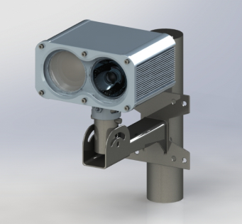
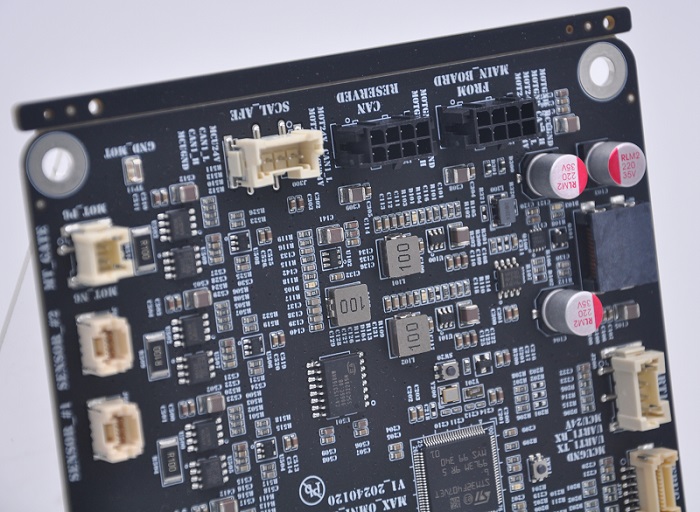
In this case, our precision PCB products were successfully deployed in the innovative product line of a leading communication equipment manufacturer, serving as the critical foundation for their cutting-edge indoor and outdoor high-speed wireless connectivity solutions.
Powering Cutting-Edge Technology:
Indoor Li-Fi Solution: Our PCB was utilized as the mainboard in the client’s high-speed Li-Fi access points and USB dongles. This application demanded a board capable of stably supporting high-speed bidirectional data transmission up to 1 Gbps and managing complex signals for multi-user access and seamless handover. Our superior PCB design ensured excellent signal integrity, delivering the low-latency, high-throughput performance required for reliability.
Outdoor Wireless Backhaul System: Within the client’s “High-Speed Backhaul Solution,” our high-frequency PCBs were integrated into the outdoor units. This scenario presented extremely rigorous requirements for stability, interference resistance, and ability to withstand environmental factors, necessitating a PCB that could guarantee consistent 1 Gbps throughput and ultra-low latency of 1-2 ms over long-distance transmissions. Our mature manufacturing processes ensure long-term, stable operation in diverse outdoor conditions.
This case demonstrates that our PCBs fully meet the demanding requirements of next-generation communication equipment for high speed, exceptional stability, high-density integration, and complex signal processing. Whether for indoor Li-Fi devices or backhaul systems built for harsh outdoor environments, our products serve as the reliable, “invisible backbone” of our client’s solutions.
In closing, PCB in manufacturing is more than just circuit boards; it is the backbone of electronics. With evolving technologies, advanced machines, and carefully chosen materials, PCBs keep products reliable and scalable. Testing methods prevent failures before they reach users. Pls send us an email at sales@bestpcbs.com if you are looking for the best PCB manufacturer in China. It is our pleasure to give our full engagement to your projects.
FAQs
Q1: What is routing in PCB manufacturing? A: Routing in PCB has two contexts:
Design stage routing: This refers to drawing the electrical connections on the PCB, determining how components are electrically linked. It is a critical step that affects PCB performance, including stability, signal quality, and interference resistance.
Manufacturing stage routing: This is the process of cutting the PCB outline from a larger production panel, creating the final board shape using CNC machines.
In daily communication, when discussing PCB design and functionality, routing usually refers to the “trace routing” on the board.
Q2: What is a BOM in PCB manufacturing and design? A: A BOM (Bill of Materials) is a detailed list of all components, materials, and specifications required to assemble a PCB, ensuring accurate sourcing and production.
Q3: What is counterbore in PCB manufacturing? A: Counterbore is a mechanical feature in PCB manufacturing that enlarges the top portion of a drilled hole, allowing components, screws, or nuts to sit flush with the PCB surface, ensuring mechanical stability and assembly flatness.
Application scenarios:
When a design includes a counterbore, PCB manufacturers typically perform two drilling steps:
Drill the through-hole using a standard drill bit.
Use a larger flat-bottom drill or end mill to create a cylindrical recess at the top of the hole.
Counterbores ensure screws or nuts are flush with the board, improving stability and reliability of the assembled device.
Key differences from countersink holes:
Purpose: Counterbore allows screws or nuts to sit flush; countersink allows conical screw heads to be level with the board.
Shape: Counterbore is cylindrical; countersink is conical.
Q4: What is a via in PCB manufacturing? A: A via is a plated hole that electrically connects copper layers in a multilayer PCB, enabling signals or power to pass between different layers.
Q5: What is chemical etching in PCB manufacturing? A: Chemical etching is the process of using acid or alkaline solutions to remove unwanted copper from a PCB, leaving only the desired circuit pattern.
Q6: What is edge plating in PCB manufacturing? A: Edge plating involves coating the side edges of a PCB with copper, improving conductivity, grounding, and mechanical strength, often used in high-frequency or connector boards.
What is amotor driver board? Let’s discover meaning, components, function, application, usage guidelines, design guide and production process for motor driver board.
Are you troubled with these problems?
Slow motor response; need millisecond-level precise control?
Multi-axis signal interference; require stable communication?
Diverse customization needs; standard solutions hard to adapt, need rapid adjustment?
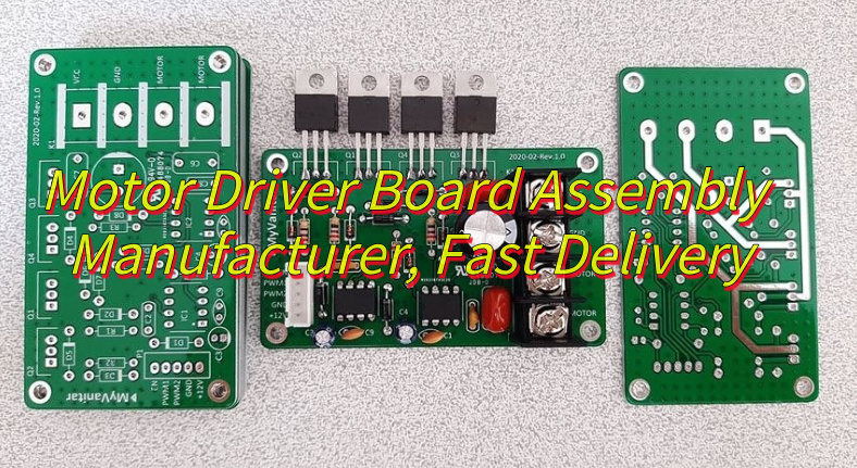
As a motor driver board assembly manufacturer, EBest Circuit (Best Technology) can provide service and solutions:
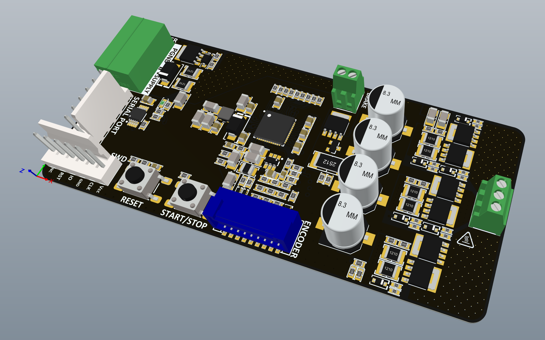
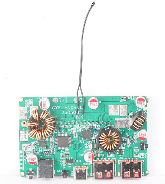
A motor driver boardis a core hardware module that bridges controllers and motors, converting low-power control signals (e.g., PWM, digital commands) into the precise current and voltage required to regulate motor start/stop, speed, direction, and rotation.
It integrates power switching components (MOSFET/IGBT), current sensors, and protection circuits to support DC, stepper, brushless, and servo motors. motor driver board’s features include overcurrent/overtemperature protection, EMI-resistant design, real-time feedback control, and high-efficiency energy conversion, ensuring stable operation for applications like robotics, automation, electric vehicles, and smart appliances.
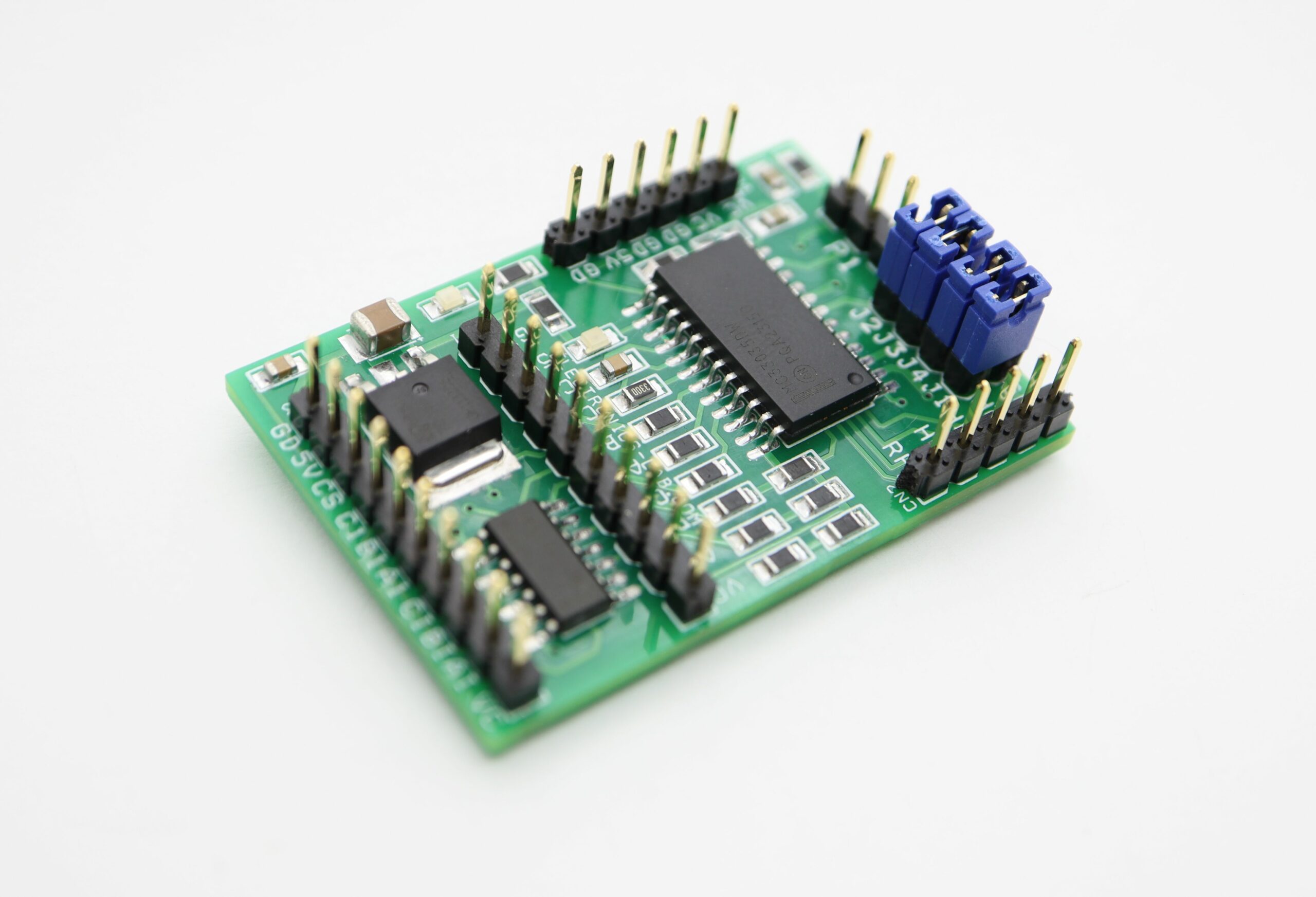
What Are the Components of a Motor Driver PCB?
Components of motor driver PCB:
Power Switches (e.g., MOSFETs): Convert low-voltage signals to high-current output, controlling motor start/stop and rotation direction.
H-Bridge Circuit: Enables bidirectional current flow via four coordinated switches, supporting forward/reverse rotation and braking.
Power Management: Stabilizes power via voltage regulators/filters, reduces EMI with layered design, and supports wide voltage/high current.
Control Circuit (MCU/Driver IC): Generates control signals, executes algorithms (e.g., PID), diagnoses faults, and isolates power/control domains.
Protection Modules: Safeguards against overcurrent, overvoltage, undervoltage, and overtemperature using sensors/TVS diodes.
Signal Processing: Hall sensors capture position/speed, processed via filtering/amplification; shunt resistors enable precise current control.
Interface & Communication: Supports protocols (CAN/SPI), uses shielded/differential pairs with ferrite beads for noise immunity, and includes debug interfaces.
Filtering & Energy Storage: Capacitors/inductors filter power ripple; RC networks reduce signal noise for accuracy.
Logic & Isolation: Optocouplers/digital isolators separate high/low-voltage domains, ensuring signal integrity and timing accuracy.
What Is the Use of a Motor Driver Board?
Functions of motor driver board:
Signal Conversion & Bridging: Serves as the core interface between controller and motor, converting low-power control signals into high current/voltage for precise driving.
Motion Control: Precisely regulates motor start/stop, speed, direction, and rotation angle, supporting forward/reverse rotation and braking modes.
Multi-Motor Compatibility: Compatible with DC, stepper, brushless, and servo motors to meet diverse application requirements.
Safety Protection: Integrates overcurrent, overvoltage, undervoltage, and overtemperature protection circuits/sensors to monitor and block abnormalities, preventing equipment damage.
Closed-Loop Feedback: Collects motor position/speed signals via Hall sensors/encoders, dynamically adjusts using algorithms (PID/FOC) to enhance control accuracy.
EMC Optimization: Uses layered PCB design, filtering circuits, and shielding to reduce EMI, ensuring stable signal transmission and system immunity.
What Are Applications of Motor Driver Circuit Board?
Applications of motor driver circuit board:
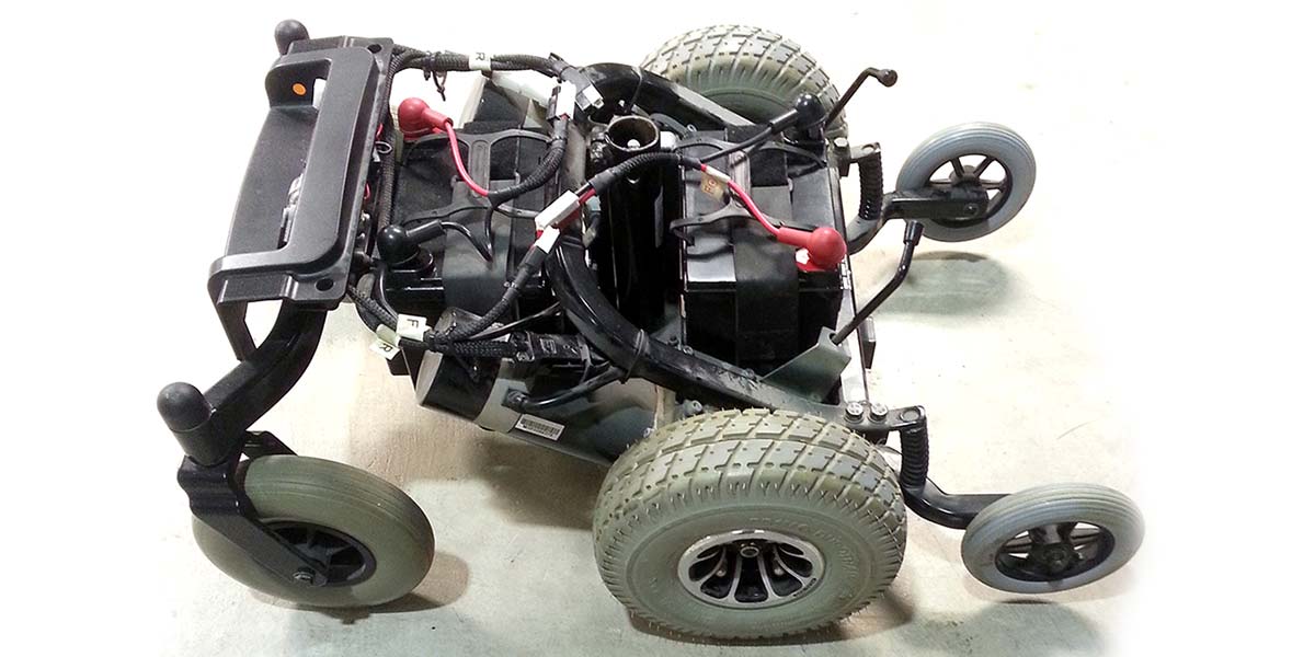
Electric wheelchair (including eye-controlled/smart wheelchair).
Robotic arm, CNC machine tool, engraving machine, 3D printer, material handling robot.
Electric car, electric scooter, drone, model aircraft, electric bicycle.
Robotic vacuum cleaner, smart home appliances, smart wristband.
Electric bed, electric height-adjustable desk, accessible elevator.
How to Use a Motor Driver Board?
1. Standardized Hardware Connection
Power connection: Use a power supply matching the motor’s rated voltage (e.g., 24V motor with 24V±10% regulated supply), connect with red-positive/black-negative standard wiring, secure with alligator clips or screw terminals.
Motor wiring: DC motor—positive to A+, negative to A-; stepper motor—phase wires in order to A-B-C-D terminals; brushless motor—connect three-phase power wires and Hall sensor signals with consistent phase.
Control signal wiring: Use physical switches/rotary potentiometers for control, e.g., rotate potentiometer clockwise to increase PWM duty cycle (accelerate motor), toggle switch to change DIR pin state (up for forward, down for reverse).
2. Manual Signal Calibration
Speed adjustment: Adjust PWM duty cycle via driver board’s built-in potentiometer (0-100% scale), each 10% rotation corresponds to stepped speed change (e.g., 20% for low-speed cruise, 80% for high-speed mode).
Direction control: Use DPDT switch for DIR pin, observe motor rotation change to confirm clear forward/reverse/stop states.
Braking: Activate BRAKE by pressing emergency stop button to short motor phases, generate reverse magnetic field for rapid braking, verify stopping time <2 seconds with tachometer.
3. Power & Protection Setup
Voltage monitoring: Use analog multimeter to check input voltage (±5% fluctuation limit), adjust voltage regulator or add filter capacitors if out of range.
Overcurrent protection: Adjust current limit via driver board’s trim pot (e.g., 5A to 10A), test with load simulator to verify protection triggers motor shutdown without burning smell.
Heat management: Apply thermal paste to heatsink, install aluminum bracket, monitor key components (e.g., MOSFET ≤80°C) with infrared thermometer, activate auxiliary fan for high temperatures.
4. Function Verification & Debugging
Basic test: Cycle “forward-reverse-brake” to check response time (≤0.5s), monitor current with clamp meter to ensure within rated range.
Closed-loop test: Connect encoder feedback, rotate motor shaft manually to check pulse proportionality, adjust PID knobs (e.g., increase P for faster response, decrease I for steady-state error) for speed control.
Troubleshooting: If motor jitters, check wiring errors or EMI; if overheating, check cooling or overload, reduce power output if necessary.
5. Safety & Maintenance
Pre-operation check: Inspect all connections before power-up, test insulation resistance (≥20MΩ) with megohmmeter, wear insulated gloves when handling rotating parts.
Emergency handling: Install independent emergency stop button in power circuit, press immediately for abnormalities; keep fire extinguisher nearby for electrical fires.
Regular maintenance: Clean dust quarterly, inspect capacitors for bulging/resistors for discoloration under magnifier, replace aged components; conduct full-function test semi-annually to meet factory standards.
How to Design a Power Wheelchair Motor Driver Board?
1. Core Circuit Module Design Parameters
Driver Circuit
Parameters: Use IR2104 isolated driver chip (gate voltage 10-20V, built-in dead time), matched with Hall sensors for current closed-loop control. Digital ground and power ground connected at a single point; sensitive signal lines filtered with ferrite beads.
Safety and Reliability Enhancements
Parameters: Redundant dual-channel input for critical control signals (e.g., PWM speed control), hardware watchdog circuit with ≤100ms response time. Temperature sensors and voltage monitoring circuits for real-time fault feedback.
2. Design Constraints
Physical Dimensions and Weight: PCB max dimensions must fit the whole vehicle (e.g., 1150x700x950mm), net weight ≤44Kg, payload ≥120Kg; trace spacing ≥10mil to prevent high-voltage breakdown.
Electrical Performance: Overcurrent protection threshold at 1.5x rated current; overtemperature protection using LM35 sensors (-40°C~150°C calibration); stall protection within 10 seconds. EMC compliant with ISO 7176-21, resistance to 26MHz-2.7GHz RF interference (≥20V/m), ESD tolerance ±8kV contact/±15kV air discharge with speed fluctuation ≤20% within 2 seconds.
Safety Standards: Must pass IEC 60601-1-2 medical EMC certification, CE certification, ISO13485:2003 quality certification, and CCC certification. Batteries/controllers/motors must individually pass GB/T 18029.21 testing.
3. PCB Layout and Routing Parameters
Layer Strategy: 4-layer PCB structure, top layer for power traces (copper thickness ≥2oz), bottom layer for control signals (50Ω impedance matching), inner layers for GND and power planes (copper coverage ≥30%).
Thermal Design: Copper foil heat dissipation under power devices, thermal vias in critical areas (thermal resistance ≤7.7°C/W); reserved mounting holes for heat sinks with thermal silicone application.
4. EMC Design Parameters
Filter Circuits: π-type filter at power input (100μH common-mode inductor + 1μF X-capacitor + 100nF Y-capacitor) to suppress conducted emissions (≤47dBμV/3m). Digital and analog grounds isolated via ferrite beads.
Shielding Measures: Metal shielding for control chip areas; critical signal traces routed away from high-frequency interference sources (e.g., wireless modules). Speed deviation ≤10°, steering deviation ≤10° when wireless devices (e.g., phones) are nearby.
5. Prototyping and Testing Parameters
Simulation Verification: SPICE tool for circuit-level simulation to validate power loop stability (loop bandwidth ≥1kHz) and control logic correctness.
Thermal Imaging: Infrared thermography to detect power device temperature rise (≤85°C) for thermal design optimization.
Long-Term Reliability: ≥1000-hour continuous aging test, vibration test per ISO 7176-13, thermal cycling test (-40°C~85°C, 500 cycles). Compliance with IPC-A-610 manufacturability standards and IPC-J-STD-020 soldering standards.
6. Documentation and DFM Parameters
BOM and Assembly: Detailed BOM with component models, parameters, capacitor values), and supplier info. Clear polarity, pad dimensions (e.g., QFN package soldering requirements). 3D models and assembly drawings with critical dimension tolerances (±0.1mm).
Certification Requirements: Mandatory compliance with IEC 60601-1-2, CE, ISO13485:2003, and CCC standards.
7. Design Considerations
Routing and Noise: Trace width ≥20mil to reduce parasitic inductance; Kelvin connections to eliminate ground bounce noise; driver signal traces ≤5cm to avoid signal reflection.
Mechanical and Environmental Protection: Stress relief slots at PCB edges to prevent solder joint fractures from vibration; moisture-resistant coating or potting (IP54 rating).
Manufacturability: Clear assembly guidelines for SMT processes, validated soldering temperature profiles, and compliance with IPC standards for component placement and inspection.
How to Assemble a Mobility Scotter Motor Driver Circuit Board?
Steps to Assemble a Mobility Scooter Motor Driver Board:
1. Component Preparation & Inspection
Verify component quantities and specifications (e.g., MOSFETs, driver ICs, capacitors) against BOM. Pre-tin power device leads and clean PCB pads if oxidized.
2. SMT Component Soldering
Use reflow soldering with temperature profile: 150°C preheat (60s), 180°C/s ramp to 220°C, 240°C reflow (40s), and natural cooling. Inspect solder joints for voids/bridging via microscope; X-ray BGA packages if applicable.
3. Through-Hole Component Installation
Solder through-hole parts (e.g., electrolytic capacitors, terminals) in height order (low to high), ensuring correct polarity for polarized components. Apply thermal grease between MOSFETs and heat sinks.
4. Electrical Verification
Perform static tests: check MOSFET GS/GD impedance, input-to-ground resistance, and signal line integrity.
Conduct dynamic tests: power up gradually, monitor LEDs/MCU status, and validate PWM signal fidelity with an oscilloscope.
5. Functional Module Testing
Configure driver IC parameters (e.g., dead time, current thresholds) via SPI/I2C. Calibrate Hall sensor alignment and test motor startup/stop sequences.
6. Protection Feature Validation
Simulate overcurrent via shunt resistor shorts; verify protection triggers (e.g., PWM disable, alarm LED). Test overtemperature response with localized heating.
7. System Integration & Optimization
Test wireless communication (e.g., Bluetooth) for real-time data exchange. Conduct environmental tests (high temperature, humidity, vibration) and EMC compliance checks.
Perform long-term aging tests and real-world road trials to confirm reliability and safety.
Why Choose EBest Circuit (Best Technology) as Motor Driver Board Assembly Manufacturer?
19-year PCBA expertise: 19 years of deep experience in motor driver board field with over 500 mature solutions, ensuring high technical maturity, reducing trial-and-error costs, and shortening development cycle by 30%+.
Strict quality control: From IQC incoming inspection to OQC final check, 6-step 100% functional testing, achieving ≥99.2% first-pass yield and ≤0.8% failure rate, ensuring equipment long-term stability.
Free DFM analysis: Design for Manufacturability evaluation identifying 20+ potential process risks, optimizing design in advance, cutting rework costs by 50%.
Stable supply chain: Strategic cooperation with 10+ core component suppliers, <7-day inventory turnover, ensuring zero material interruption and fast response to urgent orders.
One-stop service: Full-process coverage from PCB design to SMT assembly, functional testing, and packaging delivery, ensuring 100% on-time delivery and controlled project schedules.
48-hour rapid prototyping: Conventional motor driver boards prototyped within 48 hours, accelerating product validation and meeting agile development needs for robotics/industrial equipment.
Professional engineering support: 10+ senior engineers providing 7×12h technical response, resolving debugging issues within 24 hours, and boosting parameter configuration efficiency by 60%.
Environmental compliance: ISO 14001 and RoHS certified, meeting EU/North American environmental standards, ensuring smooth export and enhancing brand image.
Customized solutions: Support for power density optimization, EMC shielding design, etc., precisely matching product performance to application scenarios for differentiated competitiveness.
Welcome to contact us if you have any inquiry for motor driver board: sales@bestpcbs.com.
SMT contract manufacturing is an essential solution for businesses that aim to combine high-quality electronics production with operational efficiency. This blog provides a comprehensive overview of SMT contract manufacturing, highlighting its processes, industry applications, advantages, challenges, and how EBest Circuit (Best Technology) delivers reliable, high-quality, and customer-focused SMT solutions.
Do you face any of the following challenges in SMT contract manufacturing?
Design-to-Manufacturability Mismatch: Many clients find that PCB layouts or component placements are not fully compatible with manufacturing processes or assembly equipment, causing line adjustments or repeated rework.
Unstable Component Supply and Lead Times: Delays or shortages of critical components disrupt production schedules and extend time-to-market.
Inconsistent Soldering Quality: Issues in solder paste printing, component placement, or reflow soldering—such as insufficient solder joints, bridging, or tombstoning—can reduce yield and reliability.
High-Density / Multi-Layer PCB Assembly Challenges: Complex BGAs or multi-layer PCBs are prone to misalignment or thermal stress during precise placement and soldering.
Balancing Cost and Delivery: Customers often struggle to achieve fast delivery without compromising quality, especially for prototypes or small-batch, customized orders.
Here are the proven solutions EBest Circuit (Best Technology) applies to address these challenges:
Professional Design Review and DFM Support: Our engineering team conducts in-depth DFM (Design for Manufacturability) analysis before production, optimizing PCB layouts and component selection to ensure designs are fully compatible with manufacturing processes, minimizing rework and risk.
Reliable Supply Chain Management: We maintain long-term partnerships with top-tier distributors like TI, Mouser, and Digi-Key, with strict incoming inspection to guarantee on-time delivery of 100% genuine components.
Advanced Process and Quality Control: Full-process quality monitoring with SPI (Solder Paste Inspection), AOI (Automated Optical Inspection), and X-Ray inspection ensures consistent soldering quality and maximizes yield.
High-Precision Multi-Layer PCB Assembly: Our high-speed pick-and-place machines, reflow ovens, and selective soldering systems support complex BGAs and dense multi-layer boards, ensuring precise placement and reliable solder joints.
Flexible Production and Cost Optimization: Using MES-managed scheduling, we provide rapid prototyping, small-batch trial runs, and large-scale production while maintaining the optimal balance between cost and delivery time.
EBest Circuit (Best Technology) is a professional turnkey EMS PCB manufacturer. We have provided PCB contract manufacturing and SMT contract manufacturing services in a very competitive market for 20 years. We have our SMT factories in China and Vietnam, where we can schedule your PCBA order with a quite quick delivery time. If you have any specific needs about PCB or SMT solutions, just feel free to reach out to us at sales@bestpcbs.com.
What is SMT Contract Manufacturing?
Surface Mount Technology (SMT), short for Surface Mount Technology, is the prevailing assembly method in the modern electronics industry. SMT involves placing pinless or short-lead components, also called Surface Mount Devices (SMDs), directly onto the surface of Printed Circuit Boards (PCBs) or other substrates. These components are then soldered using precise reflow or wave soldering processes, creating a highly reliable electrical assembly.
In the context of manufacturing, SMT contract manufacturing refers to outsourcing this assembly process to specialized providers, also known as Electronics Manufacturing Services (EMS) providers. These contractors take responsibility for component placement, soldering, inspection, and quality assurance, allowing client companies to focus on design, innovation, and market deployment.
Key distinctions: It is important to clarify the difference between PCB and PCBA. A PCB (Printed Circuit Board) is simply the bare board with conductive tracks, while a PCBA (Printed Circuit Board Assembly) is the completed board with all components soldered in place. SMT is the core technology used in the assembly process, turning a PCB into a fully functional PCBA.
Forms of Contract Manufacturing: Contract manufacturing in electronics generally exists in three forms:
Full Turnkey Services: The manufacturer handles procurement of components, assembly, testing, and delivery.
Consignment or Partial Services: The client provides components, and the contractor focuses on assembly and quality control.
EMS Hybrid Models: Combining aspects of both full turnkey and consignment approaches, tailored to the client’s specific needs.
Contract manufacturing is sometimes also referred to as outsourced assembly, EMS services, or simply electronics manufacturing services. In all cases, the contractor assumes responsibility for the manufacturing process, allowing the client to reduce operational complexity and improve scalability.
SMT in Manufacturing: In manufacturing terminology, SMT specifically refers to the assembly technology, whereas “SMT contract manufacturing” describes the business model of outsourcing this technology to professional providers. This approach ensures precise component placement, consistent quality, and scalability—critical factors for high-mix, low- to high-volume electronics production.
By leveraging SMT contract manufacturing, companies benefit from advanced assembly techniques without investing heavily in equipment or labor. Additionally, professional SMT contractors implement stringent quality systems, including ISO certification, automated optical inspection (AOI), and process monitoring, which mitigate risks associated with defects and production delays.
What are the Features of SMT Contract Manufacturing Companies?
Professional SMT contract manufacturing companies provide a combination of technical expertise, robust infrastructure, and quality assurance systems. Their key features include:
State-of-the-art assembly equipment: High-speed pick-and-place machines, advanced reflow ovens, and selective soldering systems ensure precision and repeatability.
Certified quality management: ISO 9001, IATF 16949, and other industry certifications demonstrate adherence to stringent standards.
Engineering support: Experts provide DFM (Design for Manufacturability) reviews, optimizing PCB designs for production efficiency and yield improvement.
Process transparency: MES systems allow real-time monitoring, full traceability of components, and immediate response to any assembly issues.
Flexible production capacity: Facilities can handle both small prototype runs and high-volume production without compromising quality.
What is the Difference between SMT and SMC?
Understanding the distinction between SMT and SMC is critical for selecting appropriate manufacturing strategies.
SMT (Surface Mount Technology) is the assembly process used to mount components directly onto PCB surfaces, while SMC (Surface Mount Components) refers to the actual electronic components designed for SMT assembly.
Misunderstanding this difference can lead to procurement or assembly inefficiencies. Professional SMT manufacturers, like EBest Circuit (Best Technology), ensure that the process and components align perfectly for optimal performance and reliability.
What is SMT Manufacturing Process?
At EBest Circuit (Best Technology), the SMT manufacturing process is designed with precision and quality control at every step, ensuring high yield, reliability, and consistent performance for every PCB assembly. The process is structured as follows:
Incoming Material Inspection (BGA/PCB) All incoming components, including BGAs, and PCBs are carefully checked for damage, correct specifications, and storage conditions. This step prevents potential defects from entering the production line.
Pre-Bake Moisture-sensitive components and PCBs are baked to remove absorbed moisture. This is essential to prevent soldering defects such as tombstoning or BGA popcorning during reflow.
Solder Paste Application A stencil printer deposits solder paste precisely onto PCB pads. Accuracy here is critical: the correct solder volume and placement directly affect joint quality and reduce rework.
Solder Paste Inspection (SPI) SPI is a key quality checkpoint. Using advanced 3D inspection systems, we verify the solder paste volume, height, and alignment on each pad. Any deviations are flagged immediately, ensuring that only boards with perfect solder paste deposits proceed to placement. This step significantly reduces defects in later stages and improves overall yield.
Component Placement Automated pick-and-place machines position SMD components with high accuracy, even on complex multi-layer boards. Our machines are calibrated daily to maintain micron-level placement precision.
Reflow Soldering PCBs pass through a precisely controlled reflow oven. The thermal profile is optimized to melt the solder paste while minimizing thermal stress on components, ensuring strong, reliable solder joints.
Post-Reflow Cleaning Excess flux residues are removed to prevent corrosion and improve the longevity of assemblies.
Post-Oven Inspection Visual inspection and automated optical inspection (AOI) ensure that no visible defects exist after soldering.
Automated Optical Inspection (AOI) High-resolution AOI systems detect misaligned components, solder bridges, and other defects. This step acts as a final automated checkpoint before any manual corrections.
X-Ray Inspection (for BGA only) For BGAs and other hidden-pad components, X-ray inspection verifies solder joint integrity under the component. Boards without BGAs skip this step.
Secondary Soldering Any through-hole components or rework areas are soldered using selective wave soldering or manual soldering.
Cleaning Boards are thoroughly cleaned to remove any flux residues or contaminants, improving electrical performance and long-term reliability.
Programming / Functional Testing Microcontrollers and programmable devices are programmed, followed by functional testing to ensure every PCB meets its electrical and functional specifications.
Conformal Coating and Potting For enhanced protection, conformal coating or potting is applied, ensuring resistance against moisture, dust, and environmental stress.
Final Assembly Boards are assembled into final products if required, with connectors, housings, or other components added.
Labeling, Routing, and Separation All boards are labeled with traceable information, routed, and separated according to customer specifications.
Packaging and Shipment Finished products are packaged using static-shielding bags, cut tape, bubble wrap, or blister trays as needed, ensuring safe transport to customers.
Professional Highlights:
SPI inspection ensures every solder pad has correct volume and alignment before components are placed, drastically reducing defects.
X-Ray inspection for BGA guarantees hidden solder joints are reliable—crucial for high-density boards.
Functional testing combined with conformal coating ensures both performance and long-term reliability.
Automated AOI and precision pick-and-place provide consistent results even for complex multi-layer boards.
By combining these detailed steps, our factory delivers SMT contract manufacturing that is precise, reliable, and highly professional, giving clients confidence that every PCB assembly meets rigorous quality standards.
What Industries Use SMT?
SMT plays a pivotal role across multiple industries:
Automotive: Advanced driver-assistance systems (ADAS), infotainment, and power electronics require robust, high-reliability PCBs.
Medical Devices: Precision and reliability are critical in diagnostic and therapeutic devices.
Telecommunications: Networking equipment and high-speed communication devices rely on dense and precise PCB assemblies.
Industrial Automation: Robotics, sensors, and control systems demand repeatable performance and high durability.
To put it simply, the versatility and precision of SMT make it indispensable in modern electronics manufacturing. By adopting SMT, companies across these industries can achieve high-density, reliable, and efficient PCB assemblies that meet strict performance requirements. Partnering with a professional SMT contract manufacturer ensures not only technical excellence but also consistent quality, faster time-to-market, and reduced operational risks. For industries where reliability, miniaturization, and precision are critical, SMT is not just a manufacturing choice—it is a strategic advantage.
What are the Pros and Cons of SMT Contract Manufacturing?
SMT contract manufacturing has become a cornerstone for companies seeking high-quality, efficient electronics production. By outsourcing surface mount technology assembly to experienced manufacturers, businesses can leverage advanced equipment, specialized engineering support, and rigorous quality control. Understanding the advantages and potential challenges of this approach helps companies make informed decisions and maximize the value of SMT contract manufacturing.
Advantages:
High precision with reduced human error and consistent assembly quality.
Lower operational costs compared to in-house assembly lines.
Shorter production lead times for both prototypes and mass production.
Improved scalability, allowing businesses to adjust production volume based on market demand.
Challenges:
Dependence on the supplier for delivery schedules and production consistency.
Effective communication and design alignment are crucial to avoid rework.
Given these factors, while SMT contract manufacturing presents some challenges, the advantages far outweigh them for companies aiming for high-quality, scalable, and cost-effective PCB assembly. By partnering with a professional and reliable SMT contract manufacturer, businesses can focus on innovation and market strategy, confident that their products will meet strict quality and performance standards. This approach not only reduces operational burden but also enhances competitiveness in today’s fast-paced electronics market.
Where to Get Contract SMT Manufacturing
When choosing contract SMT manufacturing services, companies are primarily concerned with risk and reliability. The ideal partner does more than just assemble PCBs—they ensure the success of your project while minimizing potential risks. EBest Circuit (Best Technology) is such a partner, offering professional, trustworthy SMT contract manufacturing solutions.
Our strengths can be summarized in five key areas:
Turnkey Solutions with DFM Analysis
Comprehensive services covering PCB fabrication, component sourcing and BOM management, SMT placement, THT insertion, testing, assembly, and final packaging.
Our engineering team provides free in-depth DFM (Design for Manufacturability) analysis, proactively optimizing your design files to prevent potential manufacturing issues and cost waste, ensuring manufacturability and high yield.
Comprehensive Quality Assurance and Traceability
Our facilities are certified under ISO 9001 and IATF 16949, ensuring adherence to international quality standards.
Production lines are equipped with SPI (Solder Paste Inspection), AOI (Automated Optical Inspection), and X-Ray systems for full-process monitoring.
We maintain a complete material traceability system, allowing any product to be traced to its batch, machine, and operator, ensuring precise control of any issues.
Transparent Supply Chain and Component Control
Long-term partnerships with top distributors such as TI, Mouser, and Digi-Key guarantee 100% genuine components.
Strict incoming inspection ensures all components meet standards before assembly.
Extensive Industry Experience and Flexible Production Modes
Deep expertise in automotive electronics, medical devices, industrial control, and communication equipment, understanding the strict reliability and certification requirements of each industry.
Production lines are flexible, supporting rapid prototyping (1–2 days) to large-scale mass production, with efficient response to engineering changes.
Professional Project Management and Seamless Communication
Dedicated project managers and technical support teams for every client.
Real-time system visibility of project status, material tracking, and production data.
In summary, EBest Circuit (Best Technology) provides a professional, reliable, and customer-focused SMT contract manufacturing service through full-process control, rigorous quality management, transparent supply chains, extensive industry expertise, and professional project management. Partnering with EBest Circuit (Best Technology) means lower project risk, higher product quality, and a smooth, efficient collaboration experience.
Case of SMT Contract Manufacturing in EBest Circuit (Best Technology)
At EBest Circuit (Best Technology), our contract SMT manufacturing services span multiple industries, including automotive electronics, medical devices, industrial control systems, and communication equipment. Our extensive industry expertise allows us to handle complex PCB assemblies that demand high reliability, precise tolerances, and strict adherence to industry standards.
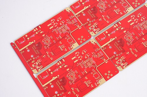
Here are some examples of actual PCBA boards we have manufactured for our clients:
Automotive Electronics: Multi-layer PCBs for advanced driver-assistance systems (ADAS), in-vehicle infotainment, and power electronics. These boards require strict quality control, high thermal stability, and precise component placement.
Medical Devices: High-density PCBs used in diagnostic equipment, wearable health monitors, and therapeutic devices. Reliability and traceability are critical in these applications.
Industrial Control & Robotics: PCBA boards for industrial automation, robotics, and sensor control systems, requiring robust design and consistent performance in demanding environments.
Communication Equipment: High-speed networking boards and RF communication devices where signal integrity and component density are key factors.
For each project, we implement automated AOI inspection, MES tracking systems, and dedicated engineering support, ensuring that every board meets design specifications and quality standards. We handle flexible production runs, from rapid prototypes to large-scale manufacturing, with rigorous testing at every stage.
This combination of industry expertise, technical capability, and end-to-end process control enables us to address customer pain points while providing reliability, repeatability, and transparency throughout the manufacturing process.
The images below illustrate the diversity and complexity of the PCBA boards we produce, showcasing the real-world applications of our SMT contract manufacturing services.
It is clear that, SMT contract manufacturing empowers businesses to achieve high-quality PCB production while focusing on their core competencies. For inquiries related to PCB design, prototyping, fabrication, or SMT contract assembly, please do not hesitate to contact us at sales@bestpcbs.com. Our team is here to provide expert support. As a turnkey EMS PCB manufacturer, EBest Circuit (Best Technology) provides superb quality China PCB manufacturing and EMS PCBA with Speedy Delivery services in a truly competitive market for nearly 20 years.
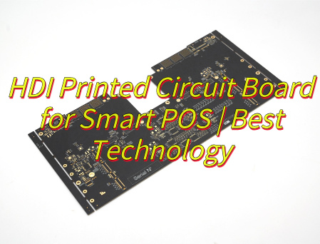
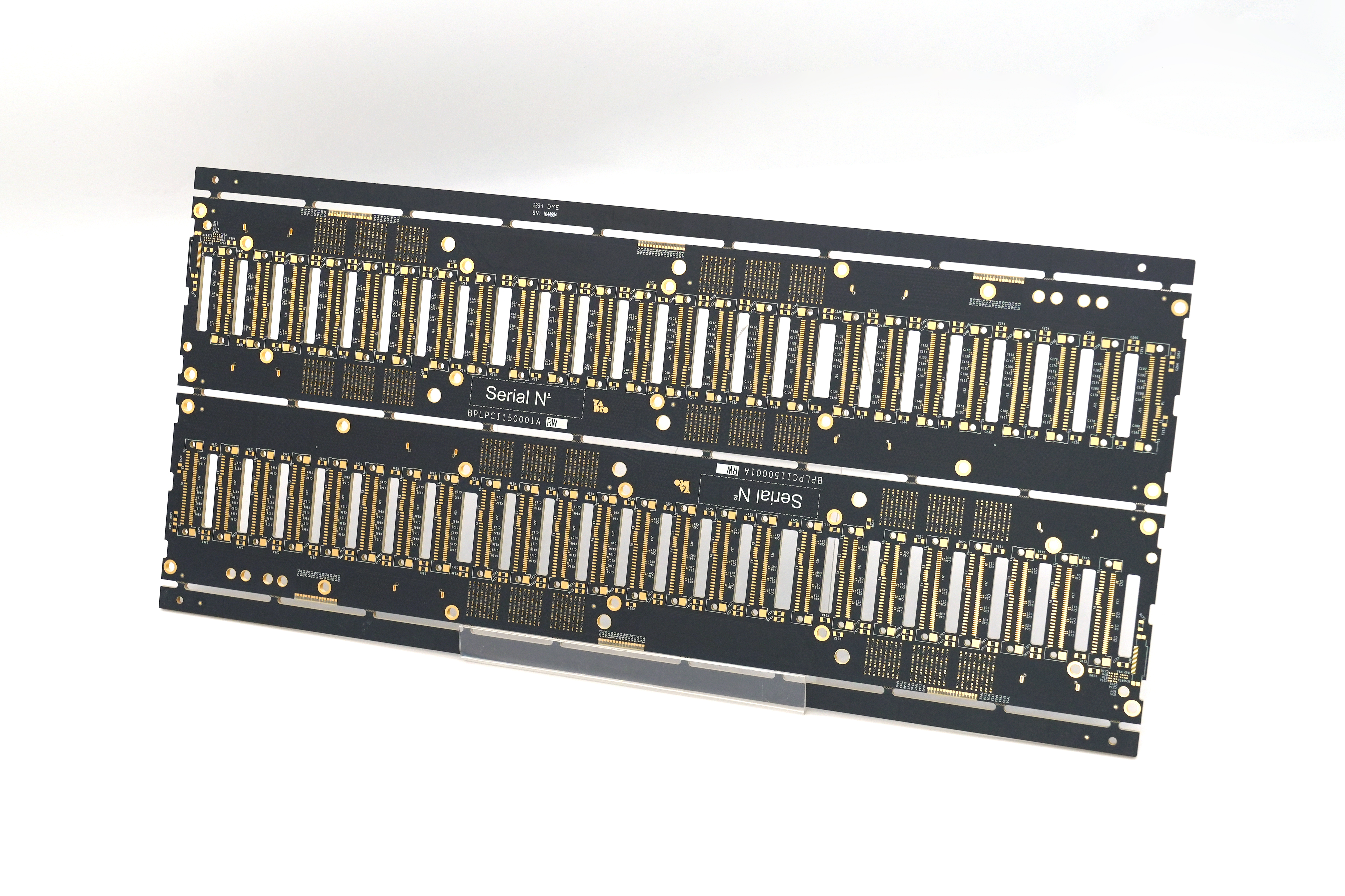
Why choose HDI printed circuit boardfor smart POS? Let’s discover its benefits, applications, technical parameter, how to balance cost and performance, signal integrity optimization solutions for HDI PCB through this blog.
Are you worried about these problems?
Does your POS mainboard freeze frequently in extreme environments?
Are traditional PCBs holding back your device’s slim design?
Poor circuit board reliability driving up after-sales costs?
As a HDI PCB manufacturer, EBest Circuit (Best Technology) can provide you service and solutions:
High-Stability HDI Stack-up: Materials resistant to low/high temps, reducing failure rates by 60%.
Ultimate Miniaturization: Adopts sub-0.1mm microvias, blind/buried via technology, and thin interlayer dielectric design, boosting wiring density by 30%-50% per unit area. Enables compact integration of multi-modules (processor, communication chip, security chip, etc.) and supports device slimming.
High-Frequency Signal Integrity: Short-path routing + low-impedance copper layer reduces signal transmission delay by 40% and crosstalk by 50%. Ensures zero data loss in high-frequency interactions (5G/4G, NFC payment) and error-free transaction processing.
Multi-Function Integration & Scalability: 8+ layer fine routing directly integrates processor, memory, biometrics, power management modules. Embedded capacitors/resistors cut external components by 30%. Reserved interfaces support AI algorithm/blockchain security module upgrades.
Efficient Thermal Management: High-Tg substrate + thermal via/layer design doubles thermal conductivity, rapidly dissipates heat from chips/power modules. Reduces thermal stress risk by 50% for 24/7 operation, extending device lifespan by 20%.
Cost-Benefit Optimization: Higher per-board cost offset by 15% reduction in overall materials (connectors, cables). Automated production (laser drilling, precision lamination) improves efficiency by 30%, shortens time-to-market by 20%, and lowers lifecycle cost by 10%.
Future-Proof Tech Compatibility: Naturally compatible with 5G high-frequency RF circuits (low-loss microstrip transmission), AI chip high-density computing needs, and biometric module fine routing. Maintains device adaptability to rapid payment scenario evolution.
Applications of HDI Printed Circuit Board in Smart POS
Integrate processor, communication module, security chip, touchscreen driver.
Optimize 5G/4G, NFC, Wi-Fi high-frequency signal transmission.
Integrate fingerprint recognition and facial recognition modules.
Carry financial-grade security chip and encryption module.
Dissipate heat from processor and power module.
Integrate power management module and reduce power impedance.
Reserve interfaces to support AI algorithms and blockchain module expansion.
Each point directly maps to the core application scenarios of HDI PCB in smart POS devices, ensuring technical accuracy and concise expression.
Technical Parameter for Smart POS HDI Printed Circuit Boards
Parameter
Specification
Substrate Material
High-frequency FR4 or polyimide materials; Tg value ≥170°C; Low dielectric constant (Dk ≤3.8)
Layer Count
4-12 layer HDI structure with blind/buried via design
Line Width/Spacing
Minimum line width: 50μm; Minimum line spacing: 50μm
Drilling Specifications
Mechanical drilling: ≥0.15mm; Laser drilling: 0.05-0.1mm; Aspect ratio ≤10:1
How HDI PCB Optimize High Frequency Signal Transmission Performance in Smart POS?
1. Precision Low-Loss Substrate Selection
Material Specifications: Utilize high-frequency low-loss substrates such as Rogers RO4350B (Dk=3.48, Df=0.0021) and Panasonic MEGTRON 6 (Dk=3.7, Df=0.002), ensuring Dk ≤ 3.5 and Df ≤ 0.0025.
Performance Enhancement: Achieves 70%+ reduction in 60GHz signal loss compared to FR-4, maintaining signal attenuation ≤2.5dB/cm for 5G/Wi-Fi 6/4G modules.
Application Compatibility: Specifically designed to meet the high-frequency requirements of smart POS modules, ensuring robust anti-interference capabilities and stable communication links.
Noise Mitigation: Grid-like power plane design reduces power noise fluctuations to <50mV, while avoiding cross-split routing preserves signal integrity for DDR4/PCIe interfaces.
Structural Advantage: Maintains unbroken reference planes under high-speed traces, critical for minimizing electromagnetic interference (EMI) and crosstalk.
3. Hierarchical Blind/Buried Via Application
Via Type Selection: Deploy blind vias (1-2 layers) for fine-pitch BGA regions and buried vias (3-6 layers) for internal layer connections, optimizing routing density.
Innovative Structure: The “1+2+1” blind via stack (top-layer blind via + internal buried via + bottom-layer blind via) increases routing density by >30% while reducing signal path length and transmission delay.
Space Optimization: Minimizes through-hole space occupation, enabling compact layout design for high-density POS motherboards.
4. Precision Impedance Control & Matching
Impedance Standards: Strictly control single-ended impedance to 50±10Ω and differential impedance to 100±3Ω via line width/spacing tuning (e.g., 0.1mm/0.1mm differential pairs).
Verification Method: TDR (Time-Domain Reflectometry) simulations validate impedance continuity, ensuring 60GHz signal return loss ≤ -28dB to minimize reflection losses.
Design Compliance: Adjusts dielectric thickness and copper weight to meet impedance targets, critical for maintaining signal integrity at high frequencies.
5. Differential Signal & Shielding Design
Differential Pair Routing: High-speed signals (USB3.0/HDMI) are routed as differential pairs with length matching error <5mil to reduce common-mode noise.
Shielding Implementation: Ground vias spaced <0.5mm alongside critical signal traces form electromagnetic shielding strips, suppressing crosstalk to <-70dB.
Anti-Interference Enhancement: Creates a protective barrier against EMI, ensuring signal purity and reliability in dense POS environments.
6. EMI/Thermal Co-Design
Electromagnetic Isolation: Ground planes segregate digital/analog domains with single-point grounding, while 0.01μF high-frequency decoupling capacitors suppress power noise.
Thermal Management: Densely arranged thermal vias (0.3mm diameter, 1mm pitch) under power devices (e.g., LDOs/MOSFETs) form heat pathways to bottom-layer thermal pads, reducing single-via thermal resistance by 40%.
Synergistic Effect: Prevents thermal concentration from degrading signal performance, ensuring system stability and longevity.
7. Simulation Verification & Process Control
Simulation Tools: HyperLynx/Allegro perform time/frequency domain simulations to validate eye diagram margin (>20%), crosstalk (<5%), and impedance matching.
Manufacturing Standards: Adheres to IPC-2221 specifications for minimum trace width/spacing (4mil/4mil), blind via diameter (≥0.1mm), and layer alignment tolerance (±50μm).
Quality Assurance: X-ray drilling inspection ensures blind via positioning accuracy, boosting first-pass yield to >95% and ensuring design manufacturability and reliability for volume production.
How to Balance the Performance and Cost of HDI Printed Circuit Boards in Smart POS?
Layer and Structure Refinement Design
Adopt symmetric stack-up structures from 1+N+1 to 3+N+3, achieve 0.1mm-level high-density wiring in the BGA region via laser microvia technology, and optimize signal path length.
PWR/GND pins penetrate 1-2 layers via microvias, freeing up inner layer wiring space, reducing layer count by 20% compared to original design, and minimizing material usage.
Wiring density increases by 40%, signal integrity improves by 12%, supports multi-layer any-layer interconnection design, and adapts to future functional expansion requirements.
Optimize interlayer coupling capacitance, reduce crosstalk, enhance high-frequency signal transmission quality, and ensure stable 5G/NFC communication.
Material Grading Selection Strategy
For high-frequency scenarios, select low Dk/Df materials (Dk ≤ 4.5, Df ≤ 0.005) such as PTFE substrate to reduce 5G signal loss by over 25%.
For conventional scenarios, use high-Tg FR-4 (Tg ≥ 170℃) to balance cost and heat resistance, preventing substrate deformation under high temperatures.
Hybrid outer-layer low-loss substrate with inner-layer conventional FR-4, achieving ≤5% performance loss, significant cost optimization, and suitability for mid-range POS devices.
Select materials with low coefficient of thermal expansion (CTE) to reduce interlayer delamination risk caused by thermal stress and improve long-term reliability.
Manufacturing Process Adaptability Enhancement
Implement mSAP/MSAP process to achieve 2mil/2mil line width, increasing wiring density by 30% and adapting to high-density wiring requirements.
Control laser drilling precision to ±0.05mm, plating void ratio ≤3%, ensuring no short/open defects in microvias.
Achieve 100% AOI inspection coverage, complemented by X-ray inspection, to identify interlayer alignment deviations and microvia filling quality.
Optimize plating uniformity to avoid excessive copper thickness variation in microvia inner walls, preventing reliability issues and extending product lifespan.
Thermal and Heat Management Co-Design
Metal substrate + buried copper block technology achieves thermal resistance ≤1.5℃/W, reducing processor area temperature by 20℃ and improving heat dissipation efficiency.
Thermal via array density ≥20/cm², combined with thermal vias to form efficient heat conduction paths and reduce thermal hotspots.
Embed liquid cooling microchannels between layers to reduce thermal stress risk by 50%, extend device lifespan by 20%, and support 24/7 high-load operation.
Use high thermal conductivity (≥2W/m·K) thermal adhesive to enhance interfacial heat conduction efficiency and reduce thermal resistance.
Power and Signal Integrity Optimization
Control PDN impedance ≤0.5Ω@100MHz and power noise ≤50mV to ensure power stability.
Ground via spacing ≤0.2mm to form low-impedance return paths, reducing ground bounce noise impact on signals.
Differential pairs adopt 4mil spacing + 50Ω impedance design, achieving ≥20dB crosstalk suppression and improving signal noise immunity.
Optimize power plane partitioning to reduce power plane resonance, enhance power integrity, and support high-speed signal transmission.
Extensibility and Maintainability Design
Reserve standardized interfaces (e.g., ZIF connectors) to support hot-swapping of AI algorithm modules and adapt to future functional upgrade requirements.
Modular stack-up structure facilitates maintenance and component replacement, reducing total lifecycle cost by 15% and improving maintainability.
Design DFT (Design for Testability) interfaces to support boundary scan and in-circuit testing, simplifying fault localization and repair processes.
Adopt removable connector design to reduce on-site repair difficulty and time, improving device availability.
19-Year Expertise for Risk Reduction: Leverage 19 years of HDI technology accumulation to provide expert consultation, reducing customer R&D trial costs by 30% and ensuring one-time certification approval for complex products like smart POS, minimizing rework expenses.
24-Hour Rapid Prototyping Service: Complete emergency order prototyping within 24 hours, accompanied by free DFM analysis reports to preemptively resolve 90% of potential production issues, accelerating product launch by 40% and securing market opportunities in emerging fields like 5G/mobile payments.
Custom Material & Process Optimization: Select high-frequency low-loss substrates + ENIG surface treatment combined with laser microvia forming (≤100μm aperture) to boost signal transmission speed by 15% and reduce power consumption by 20% for smart POS, meeting high-speed payment scenario requirements.
End-to-End Integrated Solutions: Cover full-process services from PCB design to SMT and PCBA assembly, reducing customer supply chain coordination efforts by 15%, expediting product commercialization, and supporting rapid iteration demands.
Cost Optimization Guarantee: Offer 10%-15% lower custom quotes than industry averages through scaled production and material supply chain integration, while maintaining premium material usage to enhance customer profit margins and product competitiveness.
Quick-Response Delivery Service: Ensure 7-day delivery for standard orders and 5-day expedited delivery for urgent orders, enabling customers to flexibly adapt to market fluctuations and avoid order loss or market share erosion due to delays.
Multi-Scenario Reliability Validation: Conduct customized wide-temperature (-40°C~125°C) and humidity (95% RH) tests to ensure stable operation of smart POS in extreme environments, reducing customer return rates and after-sales costs by 30%.
Below is a photo of HDI printed circuit board we did before:
Copper busbar fabrication is the cornerstone of modern power distribution, offering reliable performance and enabling the innovative use of busbar PCBs. This blog provides a comprehensive guide to copper busbars, covering their types, sizing, ampacity, fabrication process, PCB integration, advantages, and trusted sourcing options.
Do you suffer from any of the following problems?
Design Mismatch: Many customers find that busbar dimensions, thickness, or current-carrying capacity do not perfectly align with their equipment requirements, leading to project delays or repeated redesigns.
Thermal Management Issues: In high-power applications, busbars often overheat or rise in temperature too quickly, which can compromise system stability and shorten product lifespan.
Unstable Surface Finishing: Inconsistent plating quality from some suppliers can cause oxidation on the busbar surface, increasing contact resistance and reducing long-term reliability.
Poor Precision and Consistency: Problems such as misaligned holes, uneven bends, or large dimensional tolerances often require rework during installation, adding cost and time.
Lead Time and Cost Balance: Customers struggle to secure both fast delivery and competitive pricing, especially for customized or large-volume projects.
Here are some true solutions EBest Circuit (Best Technology) uses in customers’ projects.
Professional Custom Design Support: Our engineering team works directly with customers to evaluate current density, heat dissipation, and installation constraints, ensuring an optimized busbar solution from the start.
Enhanced Thermal Design: By selecting the right copper thickness, applying advanced lamination techniques, and optimizing plating, we significantly improve thermal performance in high-power environments.
Advanced Surface Treatment: Using fully automated plating lines, we provide reliable tin, silver, and nickel finishes that maintain low contact resistance and long-lasting anti-oxidation performance.
Precision Manufacturing Control: With CNC laser cutting, automated stamping, and bending processes, we guarantee accurate hole positioning, tight tolerances, and stable form consistency for seamless assembly.
Flexible Delivery and Cost Optimization: Supported by our MES system, we offer fast prototyping, small-batch trial runs, and large-scale production with reliable scheduling.
With nearly 20 years of busbar PCB industry-specific expertise and experience, EBest Circuit (Best Technology) provides fast prototyping, fabrication, and PCBA services of the copper PCB busbar. By optimizing copper usage and fabrication steps, we help you reduce total cost without compromising performance. You will enjoy our professional technical support and efficient lead time. We are your original copper busbar PCB factory. You will get our one-stop copper PCB busbar fabrication service without spending extra money or effort on other suppliers.
From automotive electronics requiring vibration resilience to data center power modules needing ultra-low impedance, our experience translates into solutions tailored for your sector. If you want to get any PCB copper busbar specification, just let us know at any moment by calling +86-755-2909-1601 or via sales@bestpcbs.com.
What is Copper Busbar Fabrication?
Copper busbar fabrication is the process of creating high-performance conductive bars that efficiently distribute electricity while meeting specific design and operational requirements. At its essence, it is not just about shaping copper; it involves selecting the right material, understanding electrical and thermal needs, and ensuring long-term reliability. Properly designed busbars are critical for applications ranging from industrial machinery to advanced copper busbar PCB systems.
Material Selection and Copper Quality The foundation of any busbar lies in its material. Most copper busbars are made from high-purity copper because it offers the best combination of electrical conductivity, mechanical strength, and thermal performance. The grade of copper used in busbars typically includes electrolytic tough pitch (ETP) copper or oxygen-free copper, which ensures minimal resistance and optimal current carrying capacity. While some busbars may incorporate copper alloys or copper-clad aluminum for cost or weight considerations, pure copper remains the preferred choice for high-current applications.
Electrical and Thermal Considerations A key factor in copper busbar fabrication is designing for the expected current load and heat dissipation. The thickness of a busbar and its cross-sectional area are determined to manage copper busbar ampacity, prevent overheating, and maintain efficiency. Engineers use practical guidelines, such as the thumb rule for busbar calculation, to determine appropriate dimensions. Flexible designs, such as flexible copper busbar or braided configurations, are often employed where vibration or dynamic movement is a concern.
Surface Treatments and Coatings To protect against oxidation and ensure long-term reliability, copper busbars are often coated. Common coatings include tin, nickel, or silver, leading to tinned copper busbar or silver plated copper bus bar options. These coatings enhance solderability, reduce corrosion, and in some cases, improve electrical contact. Selecting the right coating is critical for both traditional busbar copper panels and modern copper busbar PCB integrations.
Design and Application Considerations Copper busbar fabrication is also about tailoring the busbar to the system requirements. Factors such as electrical load, installation space, and mechanical constraints influence the final design. Engineers may design custom busbars to match a specific copper busbar material or shape, ensuring that the product delivers the intended current carrying capacity with minimal energy loss. Integration into copper PCB busbar systems is becoming increasingly common in compact, high-power electronic devices.
In summary, copper busbar fabrication is the holistic process of defining what a copper busbar should be: selecting the optimal material, specifying thickness and dimensions to meet electrical and thermal demands, and applying surface treatments to ensure longevity. It lays the foundation for efficient, reliable power distribution, whether in traditional electrical panels or integrated copper busbar PCB solutions. By understanding these core aspects, designers and engineers can ensure that their systems achieve maximum performance with minimal energy loss.
What are the Types of Copper Busbar?
In copper busbar fabrication, understanding the types of copper busbars is crucial for selecting the right solution for your electrical system or copper busbar PCB design. The choice directly impacts current capacity, thermal management, installation flexibility, and long-term reliability. Copper busbars can be categorized based on material, shape, and structural flexibility, each serving different performance and application needs.
Material-Based Classification The most fundamental distinction lies in the copper material and surface treatment:
Pure Copper Busbars: Made from high-purity copper, often T2 grade, these busbars provide superior conductivity and mechanical strength. They are available in hard and soft forms: hard copper for rigidity and precise installation, soft copper for areas requiring slight flexibility. Pure copper busbars remain the standard choice for high-current applications in industrial switchgear, distribution cabinets, and transformers.
Plated Copper Busbars: Coatings enhance specific properties for specialized environments.
Tinned Copper Busbar: Widely used to improve oxidation resistance, corrosion protection, and solderability at a reasonable cost.
Silver-Plated Copper Busbar: Offers excellent conductivity, high-temperature stability, and low contact resistance. Common in high-reliability systems, high-frequency modules, and aerospace applications.
Nickel-Plated Copper Busbar: Focuses on durability and corrosion resistance, suitable for harsh environments or frequent connection cycles.
Shape and Cross-Section Classification The busbar’s shape affects copper busbar ampacity, heat dissipation, and installation ease:
Rectangular Busbars: The most common type, balancing cost, installation simplicity, and high current capacity. Ideal for most electrical copper bus bar applications.
Round or D-Shaped Busbars: Provide better corona resistance and skin-effect performance, preferred in high-voltage or specialized switchgear applications.
Custom or Complex Shapes: L-shaped, U-shaped, or Z-shaped busbars are increasingly used in copper busbar PCB systems, EV battery modules, or power electronics modules where space optimization and compact layouts are critical.
Structural Flexibility and Integration The level of flexibility often dictates where and how the busbar can be used:
Standard Solid Bars: Simple straight bars, easy to install, widely applied in traditional distribution panels.
Pre-Processed / Ready-to-Install Busbars: Cut, punched, bent, and plated at the factory. Saves installation time, ensures precision, and minimizes human errors—ideal for modern industrial and PCB copper busbar assemblies.
Flexible or Laminated Busbars: Composed of stacked thin copper foils, providing flexibility to absorb vibrations or misalignments. Perfect for transformer connections, battery modules, or high-current electronics where slight movements occur.
Application-Driven Considerations Selecting the right type often depends on the application:
High- and Low-Voltage Distribution Cabinets: Typically use rectangular tinned copper busbars for reliability and cost-effectiveness.
EV and Energy Storage Systems: Require pre-plated, shaped busbars or flexible laminated types for tight spaces, high energy density, and durability.
High-Frequency or Aerospace Electronics: May prefer silver-plated busbars to reduce resistance losses and maintain high-frequency efficiency.
In summary, understanding the types of copper busbars helps engineers and buyers choose a solution that meets both electrical and mechanical requirements. For most industrial power distribution, tinned rectangular copper busbars offer a balance of performance and cost. For high-reliability, high-current, or compact applications, silver-plated or flexible laminated busbars integrated into copper busbar PCB systems provide superior performance. This knowledge ensures that your busbar fabrication process delivers optimized, durable, and efficient power distribution.
How to Calculate Copper Busbar Size?
As a professional Busbar PCB manufacturer, we provide precise guidance on how to calculate copper busbar size to ensure optimal current carrying capacity, thermal performance, and system reliability. Accurate sizing is crucial to maintain safety, efficiency, and compliance in high-power applications.
1. Core Objectives and Key Parameters
The purpose of calculating copper busbar size goes beyond obtaining a simple dimension. It ensures safe and efficient current transmission while considering thermal and electrical constraints. The main factors include:
Current carrying capacity: Determines the maximum continuous current the busbar can safely conduct without excessive heating.
Temperature rise: The allowable temperature increase (e.g., 30°C, 40°C, 55°C above ambient) directly affects the cross-sectional area required. Standards such as UL and IEC provide guidance for different applications.
Short-circuit withstand: Copper busbars must resist mechanical deformation or melting under high short-circuit currents for a few seconds.
Voltage drop: Especially in long connections, voltage drop ΔV = I × R must be within acceptable limits to maintain stable operation of the system.
2. Step-by-Step Calculation Process
Step 1: Define Basic Conditions
Rated current (I): Determine the continuous current the system will carry.
Ambient temperature (Tambient): Identify the maximum operating temperature around the busbar.
Allowable temperature rise (ΔT): Decide the permissible temperature increase based on insulation and application requirements. Final allowable temperature: Tfinal = Tambient + ΔT.
Step 2: Preliminary Cross-Section Area Selection
The cross-sectional area (A) can be estimated using the thumb rule for busbar calculation or reference tables for copper busbar ampacity. For rectangular copper busbars:
Formula: A = I / J Where: A = required cross-sectional area in mm2, I = rated current in A, J = allowable current density in A/mm2 (depends on copper grade, temperature rise, and installation).
Notes on adjustment:
Ambient temperature correction: Reduce J if operating above standard 40°C conditions.
Parallel busbars: When multiple busbars are used in parallel, total current capacity is slightly less than the sum due to heat accumulation. Multiply by a correction factor (<1) as needed.
Step 3: Short-Circuit Verification
For short-circuit conditions, the busbar must withstand high instantaneous currents. Approximate temperature rise during short-circuit can be estimated by:
ΔT = (Isc)2 × t / (k × A2) Where: Isc = short-circuit current in A, t = short-circuit duration in seconds, A = cross-sectional area in mm2, k = material constant for copper (≈115 for pure copper, unit depends on formula system).
This ensures the final temperature is below copper softening point (~250°C).
Step 4: Voltage Drop Verification
Voltage drop along the busbar:
ΔV = I × R Where R = ρ × L / A, ρ = resistivity of copper (≈0.0175 Ω·mm2/m), L = length of busbar in meters, A = cross-sectional area in mm2. Ensure ΔV is within the acceptable percentage of system voltage (typically 3–5%).
All in all, accurately calculating copper busbar size requires a combination of professional knowledge, standards reference, and practical adjustments. The recommended approach is:
Define all design parameters: rated current, ambient temperature, allowable temperature rise, and short-circuit conditions.
Calculate preliminary cross-section: using current density (J) and copper grade (grade of copper is used in busbars), apply correction factors for ambient temperature and parallel busbars.
Verify short-circuit capability: ensure temporary currents do not exceed thermal limits using the ΔT formula.
Check voltage drop: confirm ΔV = I × R is within system tolerances.
This systematic method provides customers with a reliable, technically validated size selection for Busbar PCB applications, supporting safe, efficient, and long-lasting operation.
How to Calculate Copper Busbar Ampacity?
As a professional Busbar PCB manufacturer, accurately calculating the ampacity—the maximum current a copper busbar can safely carry—is critical to ensure reliability, efficiency, and longevity of your high-power electronic systems. Ampacity depends on multiple factors, including copper grade, cross-sectional dimensions, ambient temperature, and cooling conditions. Correct calculations prevent overheating, reduce energy loss, and ensure stable operation.
1. Core Principles
Before performing any calculation, it is important to understand the underlying factors that affect busbar ampacity:
Copper grade: The conductivity and mechanical properties of copper determine how much current the busbar can safely carry. Commonly used is T2 copper (≥99.9% purity).
Cross-sectional area: Wider and thicker busbars carry higher current. For rectangular busbars, ampacity roughly scales with width × thickness coefficient.
Number of layers: Multiple stacked busbars increase ampacity but require correction factors to account for heat accumulation.
Ambient temperature: Higher temperatures reduce ampacity. A correction factor adjusts for operating temperature above 25°C.
Cooling conditions: Forced cooling or natural convection affects permissible current density.
Four-layer: Ampacity ≈ 2.45 × single-layer ampacity (generally not recommended; better to use a custom-shaped busbar)
Step 3: Correct for ambient temperature
If operating at temperatures other than 25°C:
Ampacity40°C = Ampacity25°C × 0.85
Step 4: Consider material differences
For comparison, aluminum busbars carry less current:
AmpacityAl = AmpacityCu ÷ 1.3
3. Practical Tips
Use busbar tables and handbooks whenever possible to verify calculations.
Derate for safety margins in long-term or continuous operation.
Consider cooling and installation constraints: Ensure enough spacing for heat dissipation, especially in multi-layer arrangements.
Check compliance with standards such as IEC 61439 or UL regulations for busbar ampacity in electrical panels.
In closing, calculating copper busbar ampacity requires combining empirical formulas with practical knowledge. By considering copper grade, busbar dimensions, number of layers, ambient temperature, and correction factors, engineers can determine reliable ampacity for Busbar PCB applications. This ensures safe, efficient, and long-lasting performance in industrial, power, and renewable energy systems.
How to Clean Copper Busbar Electrical?
As a professional Busbar PCB manufacturer, we understand that proper maintenance and cleaning of copper busbars is essential for ensuring reliable electrical performance, longevity, and safety. Contamination on busbars—such as oxidation, dust, grease, or environmental deposits—can significantly increase contact resistance, reduce current-carrying capacity, and potentially lead to overheating or equipment failure. A systematic cleaning process preserves both the electrical and mechanical integrity of busbars in high-power systems.
1. Identify the Contamination
Before cleaning, it is important to assess the type and severity of contamination:
Oxidation/Tarnish: Copper naturally forms a thin oxide layer when exposed to air. While minor oxidation has little effect on low-current circuits, it can increase contact resistance in high-current busbar PCB applications.
Dust and Particulates: Accumulated dust can absorb moisture, causing localized heating and corrosion.
Grease and Oil: Residues from handling or assembly may insulate contact surfaces and reduce conductivity.
Environmental Deposits: In industrial or outdoor environments, pollutants such as sulfides or chlorides can accelerate corrosion.
2. Recommended Cleaning Materials
Select non-abrasive, electrically safe cleaning materials to avoid damaging the copper surface or its plated coatings:
Electrical Contact Cleaners: Specifically formulated to dissolve grease and remove oxide layers without leaving conductive residues.
Soft Brushes or Lint-Free Cloths: Avoid metal brushes that may scratch or deform busbar surfaces.
Isopropyl Alcohol (IPA): Commonly used to remove oil or flux residues; evaporates quickly and leaves minimal residue.
Optional Abrasive Pads (Fine Grade): For stubborn oxidation, a fine-grade pad may be used lightly. Take care not to remove protective tinning or silver plating if present.
Tip: For silver-plated copper bus bars, avoid harsh abrasives that can wear off the plating and compromise long-term conductivity.
3. Cleaning Procedure
A structured cleaning process ensures safety and effectiveness:
Power Off and Isolate: Always disconnect the busbar from the circuit. Confirm there is no residual voltage before proceeding.
Dry Surface Cleaning: Remove loose dust or particulate matter with a soft brush or compressed air.
Surface Degreasing: Apply a small amount of electrical contact cleaner or IPA with a lint-free cloth. Wipe thoroughly to remove grease or oil.
Oxidation Removal: For light oxidation, gently wipe with a fine abrasive pad. For severe oxidation, a chemical copper cleaner may be required, followed by rinsing with IPA.
Final Inspection: Ensure no residues, fibers, or moisture remain. Check for scratches or damage that could affect electrical performance.
Optional Protective Coating: In high-humidity or corrosive environments, a thin protective layer such as tinned coating or special anti-oxidation spray can prolong service life.
4. Maintenance Frequency
The cleaning schedule depends on the operating environment and current density of the busbar:
Indoor, clean environments: Every 6–12 months may suffice.
High-current industrial equipment or chemical environments: Quarterly inspections and cleaning are recommended.
Battery or renewable energy modules: More frequent checks if high moisture or sulfide exposure is expected.
Regular maintenance reduces the risk of localized overheating, ensures stable ampacity, and extends the lifespan of Busbar PCB systems.
5. Key Considerations and Safety Tips
Always wear insulated gloves and safety glasses during cleaning.
Avoid excessive mechanical force to prevent bending or scratching the busbar.
Never use water or conductive solvents that may leave residues.
Document maintenance activities to track trends in oxidation or contamination over time.
Ensure proper ventilation when using chemical cleaners to avoid inhalation hazards.
In brief, proper cleaning of copper busbar electrical connections is a critical step for maintaining performance, safety, and longevity. By identifying contaminants, using safe cleaning materials, and following a structured procedure, engineers can preserve the electrical conductivity and mechanical integrity of busbars in high-current systems. Regular maintenance reduces downtime, prevents energy loss, and ensures that your Busbar PCB solutions operate reliably under continuous load.
What is Current Density of Copper Busbar?
Current density (J) is defined as the amount of electric current flowing per unit cross-sectional area of a copper busbar. It is usually expressed in amperes per square millimeter (A/mm2) and plays a critical role in determining the safe operating capacity of a busbar in a Busbar PCB application. Understanding and controlling current density is essential for ensuring electrical reliability, thermal stability, and longevity of high-current systems.
1. Why Current Density Matters
As a Busbar PCB manufacturer, we emphasize that current density directly affects:
Overheating Risk: High current density increases the temperature rise in the copper material. Excessive heat can degrade the PCB substrate, solder joints, and insulating layers. This is especially important in high-power modules, inverters, and distribution panels where continuous high current is expected.
Material Stress and Reliability: Uneven current density can create hotspots, which may cause localized expansion, mechanical stress, or even warping of the copper traces. Over time, this reduces the lifespan of the Busbar PCB.
Energy Efficiency: High current density increases resistance losses (I2R), causing energy loss. Properly designed copper busbars balance cross-sectional area and current to minimize these losses and maintain efficient power delivery.
Thermal Management: Current density must be coordinated with cooling conditions—airflow, thermal vias, or heatsinks—to ensure the PCB can operate continuously without exceeding temperature limits.
2. How Current Density is Calculated
The current density J can be expressed as:
J = I / A
Where: – J = current density (A/mm2) – I = current through the busbar (A) – A = cross-sectional area of the busbar (mm2)
Example Considerations for Busbar PCB Design:
Copper Grade: Different copper grades have slightly different resistivity. High-purity copper (≥ 99.9%) reduces losses and allows slightly higher current density.
Busbar Thickness: Thicker busbars reduce current density for the same current, lowering temperature rise.
Ambient Conditions: Higher ambient temperatures or limited airflow require lowering the permissible current density to prevent overheating.
Layering & Distribution: Multi-layer copper busbars or parallel traces can reduce the effective current density on each layer, distributing heat more evenly.
3. Recommended Guidelines for Busbar PCB
While exact values depend on design specifications, cooling, and ambient conditions, typical design ranges for continuous operation in copper busbars are:
Single-layer copper trace on Busbar PCB: 1.2 – 2.5 A/mm2
High-frequency or pulsed applications: Design conservatively, 0.8 – 1.5 A/mm2
As a Busbar PCB manufacturer, we always verify these values through thermal simulation and empirical testing, ensuring that the busbar can operate safely at full load without degradation.
4. Factors Affecting Safe Current Density
Copper Material and Purity: Higher-purity copper reduces resistive heating and allows higher current density. Alloying or plating (e.g., silver-plated copper busbar) can improve surface conductivity and reduce oxidation risks.
Trace Geometry and Cross-sectional Area: Wider or thicker busbars lower current density for the same current. Custom shapes (L-shaped, U-shaped) can be designed to optimize current distribution and heat dissipation.
Ambient Temperature & Cooling: Busbar operating at 40°C can safely carry more current than in a 60°C enclosure. Use of heat sinks, forced air, or PCB copper pours reduces effective current density per unit area.
Layer Stacking or Parallel Traces: Multi-layer or parallel busbar PCB design reduces individual layer current density. Allows higher total current without exceeding thermal limits of each trace.
5. Practical Advice for Designers
Always calculate current density before finalizing the Busbar PCB layout.
Combine theoretical calculations with thermal simulation to predict hot spots.
If current density exceeds recommended limits, increase copper thickness, width, or number of layers.
For high-reliability systems, consider reducing the current density by 10–20% as a safety margin.
Coordinate with copper busbar fabrication processes to ensure that plating, bending, and lamination do not reduce the effective cross-sectional area.
To wrap up, current density is a key design parameter for Busbar PCBs. Proper calculation ensures:
Safe continuous operation
Minimization of energy losses and hotspots
Extended lifespan of copper traces and PCB substrate
Reliability in high-current applications such as inverters, battery modules, and power distribution systems
As a professional Busbar PCB manufacturer, we provide clients with guidelines, simulations, and engineering support to achieve optimal current density in every custom design, balancing performance, efficiency, and safety.
What is the Process of Copper Busbar Fabrication?
The process of copper busbar fabrication is a critical step to ensure optimal electrical performance, mechanical strength, and reliability in high-current applications. For Busbar PCB systems, understanding each stage of fabrication allows engineers and designers to anticipate performance, select proper materials, and ensure safe integration into electrical assemblies.
1. Material Selection
The process begins with selecting high-grade copper suitable for the intended electrical load and environmental conditions. Common choices include:
Electrolytic Tough Pitch (ETP) Copper: High conductivity (~101% IACS) with excellent mechanical strength. Frequently used for general industrial busbars.
Oxygen-Free Copper (OFC or OFHC): Superior conductivity and corrosion resistance; preferred for high-frequency, high-reliability applications, such as aerospace or critical inverter busbar PCBs.
Copper Alloys (if required): Sometimes small amounts of silver or other metals are added to improve mechanical strength without significantly compromising conductivity.
Selecting the right copper grade for your busbar ensures low resistance, minimal energy loss, and long-term thermal stability under high current density.
2. Cutting and Shaping
Once the copper grade is selected, busbars are cut and shaped according to the design specifications:
Cutting: Precision cutting is achieved using laser cutters, water jet systems, or mechanical shears, ensuring minimal burrs and accurate dimensions.
Bending/Forming: CNC bending machines or manual presses shape the busbar into required geometries, such as L-shaped, U-shaped, or custom forms for compact PCB layouts. Proper bending avoids micro-cracks and maintains consistent cross-sectional area, which is crucial for current density management.
Drilling/Punching: Holes for screws, bolts, or PCB connections are precisely drilled or punched to maintain alignment and mechanical integrity. Modern CNC punching ensures dimensional accuracy and repeatability.
3. Surface Treatment and Coating
After shaping, surface treatments enhance both conductivity and corrosion resistance:
Tin Plating (Tinned Copper Busbar): Common for busbars in power electronics; prevents oxidation and improves solderability.
Silver Plating: Offers superior conductivity and oxidation resistance, typically used in high-reliability or high-frequency applications.
Nickel or Zinc Coatings: Used in specific environmental conditions for additional corrosion protection or wear resistance.
Surface coating also reduces contact resistance and improves long-term performance in Busbar PCB assemblies.
4. Quality Control and Inspection
Quality checks are conducted at multiple stages to ensure that dimensions, conductivity, and mechanical properties meet design requirements:
Dimensional Inspection: Verifying length, width, thickness, and hole alignment.
Electrical Testing: Checking resistance, continuity, and, in some cases, high-current testing to verify ampacity.
Thermal Testing: Evaluating performance under expected operating temperatures to prevent overheating in high-current applications.
Surface Inspection: Ensuring plating or coating is uniform and free of defects.
5. Assembly and Packaging
Once fabricated, copper busbars are cleaned, dried, and prepared for Busbar PCB integration:
Handling and Packaging: Proper handling prevents scratches, contamination, or deformation.
Integration Support: For PCB assemblies, busbars are often pre-bent or shaped to match board layouts, making installation faster and more reliable.
6. Modern Fabrication Techniques
Advanced fabrication combines CNC machining, automated plating lines, thermal inspections, and laser cutting to maintain tight tolerances, improve efficiency, and reduce human error. These methods are especially critical in high-current Busbar PCB applications, where even small deviations can affect performance or safety.
Key Takeaways
Material Matters: Selecting the right grade of copper ensures low resistance, high thermal stability, and long-term reliability.
Precision Shaping: Accurate cutting, bending, and drilling maintains proper current density and mechanical integrity.
Surface Treatment: Proper plating or coating reduces oxidation, improves conductivity, and extends lifespan.
Integration-Ready: Fabricated busbars are prepared for seamless incorporation into Busbar PCBs, reducing installation errors and enhancing reliability.
By following a detailed fabrication process, copper busbars in PCB applications achieve optimal electrical performance, high thermal tolerance, and long-term durability, enabling them to handle demanding power distribution, inverter, and industrial applications safely and efficiently.
How Are Copper Busbars Integrated into PCB Designs?
In modern high-power electronics, copper busbars are no longer limited to traditional standalone metal bars. Instead, busbar PCB solutions integrate copper busbars directly into the printed circuit board. This approach provides significant advantages in terms of space efficiency, thermal management, and electrical performance.
1. Layout Design for Busbar Integration
The integration starts with careful PCB layout planning. Engineers must design the board to accommodate busbar traces that handle high currents without causing voltage drops or hotspots. Key considerations include:
Current Path Optimization: Busbar traces should follow the shortest path between power input and output points to minimize resistance.
Pad and Via Placement: Properly sized and positioned pads and vias ensure reliable soldering and mechanical stability for copper busbar PCB connections.
Segregation of High and Low Voltage Zones: Isolating high-current traces reduces the risk of interference with sensitive signals.
This design phase is critical to maximize the current carrying capacity of copper busbars while maintaining overall board reliability.
2. Copper Thickness and Material Selection
The grade of copper used in busbars and its thickness directly affect performance. Standard copper PCB layers may not suffice for high-current applications, so busbar layers often use thicker copper plating or embedded copper strips:
High-grade Copper Material: Using electrolytic tough pitch (ETP) copper or oxygen-free copper ensures low resistivity and high thermal stability.
Thickness Selection: Engineers calculate the required copper thickness based on ampacity requirements, voltage drop, and thermal limits. This ensures that the PCB copper busbar can handle the expected load without overheating.
Plating Options: Additional surface treatments such as silver-plated copper busbars or tinned copper busbars may be applied to reduce contact resistance and improve solderability.
3. Mechanical Stability and Thermal Management
Integrating copper busbars into a PCB is not only about current flow—it also involves mechanical and thermal considerations:
Structural Reinforcement: Thick busbar traces can create stress points on the PCB. Designers may use additional layers, vias, or embedded support structures to maintain mechanical integrity.
Heat Dissipation: Embedded busbars act as thermal conduits, spreading heat generated by high currents across a larger copper area. This is crucial in high-power inverters, EV battery modules, and industrial LED systems.
Flexible Busbar Layers: In some designs, flexible copper busbars or laminated copper layers are used to absorb mechanical vibration and reduce stress, improving long-term reliability.
4. Manufacturing and Integration Considerations
Implementing copper busbars in PCBs requires precise fabrication techniques:
Lamination: Multi-layer boards may have busbar layers laminated between standard signal layers.
CNC Milling or Laser Routing: Precise copper cutouts allow integration of busbar traces while avoiding short circuits or hotspots.
Quality Control: Post-fabrication testing ensures the busbar PCB meets required current ratings, thermal performance, and dimensional accuracy.
5. Applications and Performance Benefits
Integrated copper busbars enhance PCB performance in compact, high-power applications:
Electric Vehicles (EVs): Busbar PCBs efficiently distribute battery power while minimizing board space.
Industrial Inverters: High-current busbars reduce resistance and thermal stress in power conversion modules.
High-power LED Systems: Embedded busbars provide uniform current distribution, reducing voltage drops and hotspots.
Key Takeaways
Efficient Layout Design: Optimized trace paths and pad placement are critical for performance and reliability.
High-quality Copper Selection: The grade of copper used in busbars and thickness directly impacts ampacity, thermal stability, and energy efficiency.
Mechanical and Thermal Reliability: Proper reinforcement and heat management extend PCB lifespan and prevent failures.
Advanced Manufacturing: Laminated layers, precise routing, and rigorous quality control ensure safe, high-performance busbar PCB integration.
Wide Applications: EVs, industrial inverters, and high-power LEDs benefit from compact, high-efficiency busbar PCB designs.
By embedding copper busbars into PCBs, engineers achieve superior current distribution, enhanced heat dissipation, and reduced footprint, enabling modern electronics to meet ever-growing performance demands.
Why Use PCB Bus Bars?
In the past, engineers relied on widening copper traces on PCBs to handle increasing current demands. But as chips grow more powerful and compact, this traditional approach has reached its limits. Voltage drop, overheating, and wasted board space have become serious bottlenecks in modern power delivery design.
To address these challenges, PCB bus bars have emerged as an integrated solution. Acting as high-current conductors embedded directly into the PCB, bus bars provide superior conductivity, thermal performance, and mechanical strength within a compact footprint.
Core Advantages
1. Handle Extremely High Currents
Comparison: A wide copper trace might carry only tens of amps, while a PCB bus bar can handle several times—or even tens of times—more.
Reason: Much larger cross-sectional area and thickness of the bus bar.
Value: Enables designs like motor drives, power modules, and servers to handle hundreds of amps reliably.
2. Ultra-Low Impedance and Voltage Drop
Comparison: PCB copper traces have relatively higher resistance, causing voltage drops.
Reason: Bus bars use pure copper or brass with large cross-sections, ensuring very low resistance.
Value: Improves efficiency, reduces energy loss, and keeps end-voltage stable under load.
3. Superior Heat Dissipation
Comparison: Wide traces have limited heat dissipation capacity.
Reason: Bus bars act as heat sinks with high thermal mass and greater surface area.
Value: Controls hot spots, improves thermal reliability, and extends service life.
4. Saves Valuable PCB Space
Comparison: Supporting large currents with wide traces requires extensive copper layers or stacked planes.
Value: Bus bars achieve the same—or higher—current capacity in smaller areas, freeing space for more components or signal routing. This supports miniaturization and high-density layouts.
5. Mechanical Stability and Connection Reliability
Comparison: PCB pads may crack or degrade under stress from repeated connections or vibration.
Value: Bus bars provide rigid power connection points that withstand mechanical stress, ideal for battery packs, automotive systems, and heavy cabling.
6. Lower Inductance, Better Power Integrity
Comparison: Parallel traces on PCBs create higher parasitic inductance.
Value: Bus bars minimize inductance, reducing voltage spikes and noise in fast-switching power devices such as GaN or SiC semiconductors.
PCB Bus Bars vs. Traditional Methods
Think of PCB bus bars not as a universal solution, but as a strategic choice depending on your design needs:
Current above 50A? → Strongly consider bus bars.
PCB space is extremely limited? → Bus bars free up board area.
Thermal bottleneck? → Bus bars provide superior cooling.
Current below 10A and cost-sensitive? → Wide copper traces may remain more economical.
Frequent design revisions? → PCB traces are more flexible to modify than bus bar layouts.
This decision matrix helps balance performance, cost, and flexibility.
Real-World Applications
PCB bus bars shine in industries where high current, tight space, and reliability converge:
Electric Vehicles: On-board chargers, motor controllers, battery management systems.
Data Centers: Server rack power distribution, GPU cluster supplies.
Renewable Energy: Solar inverters, energy storage converters.
Consumer Electronics: High-end gaming laptops, workstation power modules.
Practical Considerations
Despite their advantages, PCB bus bars are not without trade-offs:
Cost: Extra copper material and assembly increase costs compared to traces.
Design Flexibility: Bus bar designs are less adaptable once finalized.
Assembly Complexity: May require selective soldering, press-fit, or special fixtures.
These factors should be weighed carefully during the design phase.
To conclude, as electronic systems evolve toward higher power, higher density, and higher reliability, traditional PCB traces can no longer keep up with the demands of power delivery. PCB bus bars provide a transformative solution: high current capacity, low impedance, superior cooling, space savings, and robust mechanical stability. When your project faces challenges like high current, thermal stress, or space limitations, PCB bus bars should not just be considered an alternative—but a key design option for the future.
Where to Get PCB Copper Busbar?
Finding a PCB copper busbar supplier is not as simple as comparing quotes. The wrong choice can mean delayed projects, unstable performance, or even on-site failures. To avoid costly risks, engineers must evaluate suppliers with the same rigor they apply to design decisions.
1. Technical Customization
Many suppliers sell copper busbars as generic components. But in high-power applications like EV power electronics, server racks, or industrial inverters, every design carries unique thermal, space, and vibration challenges.
At EBest Circuit (Best Technology), we treat busbars not as parts, but as engineered solutions.
Deep application knowledge: We have delivered custom Busbar PCB solutions for industries as diverse as electric vehicles, renewable energy, and data centers, where reliability under vibration and high current is non-negotiable.
Collaborative design support: Our engineers provide free DFM (Design for Manufacturability) reviews, helping optimize layouts before production begins—avoiding costly rework and shortening time-to-market.
Seamless data exchange: We support direct import of your CAD files (such as .step), ensuring precise translation of your design intent.
2. Quality Assurance
A copper busbar must not only conduct current, it must do so consistently, safely, and with long-term reliability. EBest Circuit (Best Technology)’s manufacturing backbone guarantees that consistency.
Precision fabrication: We employ high-speed CNC punching and bending, achieving dimensional tolerances within ±0.05mm for flawless assembly.
Flexible surface treatments: Options such as tin, silver, or nickel plating improve conductivity, corrosion resistance, or solderability, chosen based on your application’s requirements.
Certified quality systems: With IATF16949, ISO9001, ISO13485, and AS9100D certifications, combined with 100% continuity testing, every product leaves our line backed by documented reliability.
3. End-to-End Service and Support
Ordering a custom PCB busbar is more than just a purchase—it’s a project. EBest Circuit (Best Technology) supports you through every stage:
Rapid prototyping: Prototypes delivered in as little as 3–5 days, enabling fast design iterations.
Scalable production: Whether you need small pilot runs or high-volume manufacturing, we adapt to your product lifecycle.
Transparent project management: Each project is assigned a dedicated manager, keeping you informed with real-time production updates.
Fundamentally, choosing a PCB copper busbar supplier is not about the lowest quote. It is about finding a partner who understands your application, delivers uncompromising quality, supports you through the process, and offers real long-term value. EBest Circuit (Best Technology) is more than a manufacturer—we are a strategic partner who combines engineering expertise, proven quality, and reliable service to help you achieve safe, efficient, and future-ready power solutions.
In essence, understanding copper busbar fabrication and its integration into PCB (Printed Circuit Board) solutions is crucial for modern high-power electronics. Partnering with EBest Circuit (Best Technology) resolves common challenges in your Busbar PCB projects, such as voltage drop, space constraints, and thermal management. Pls send your design sketch or requirements to sales@bestpcbs.com for a quick, free review and quote. Our certified processes, customization options, and engineering expertise deliver reliable busbar PCB solutions that boost performance, helping you achieve superior results in demanding electrical applications.
Parts of a PCB form the backbone of every electronic product. In this blog, we break down the essential parts of a PCB, explain their types and functions, guide readers on component identification and reading reference designators, explore copper layers and the PCBA process, and etc.
Adopt advanced inspection technologies: To address PCB defect detection issues, image processing and machine learning techniques can be used for PCB defect detection and classification.
Provide detailed PCB component identification guides: To help customers better identify and understand components on a PCB, the detailed guides can be offered by EBest Circuit (Best Technology), including component types, functions, and identification methods.
Optimize PCB manufacturing and assembly processes: By adopting advanced soldering techniques and automated assembly equipment, the reliability and performance of PCBs can be significantly improved.
Offer customized PCB design and manufacturing services: Provide personalized PCB design and manufacturing solutions based on the customer’s specific requirements and application scenarios.
You will learn the parts of a PCB from two aspects: the physical structure of the board and the electronic components mounted on it. By understanding both, you will not only see how a printed circuit board works, but also understand how these parts interact to create reliable, functional devices.
1. The Structural Parts of a PCB
Every PCB starts with a layered foundation that makes signal transmission possible. These layers are not just materials; they each serve a distinct purpose:
Substrate (Base Material): Usually fiberglass such as FR4. It gives the board mechanical strength and electrical insulation.
Copper Layer: Thin copper sheets form the traces, pads, and planes that carry current and signals.
Pads: Small exposed copper areas where components are soldered. Pads act as the anchor points between the board and devices.
Vias: Tiny drilled holes plated with copper that connect one copper layer to another. They allow signals to pass vertically inside multilayer boards.
Solder Mask: The protective colored coating (often green) that covers copper traces. It prevents oxidation and short circuits during soldering.
Silkscreen: Printed labels showing reference designators, pin 1 indicators, and helpful text. It works like a map for engineers and technicians.
Traces (Conductive Paths): Copper lines that route signals from one component to another. Their width and spacing directly affect performance, especially in high-speed circuits.
Together, these elements form the “skeleton” and “nervous system” of the PCB. Without them, no component could be mounted or connected properly.
2. The Electronic Components on a PCB
While the structure gives shape, the mounted components bring the circuit to life. These are the common ones you’ll find:
Resistors: Control current flow and set voltage levels.
Capacitors: Store and release charge, filter noise, and stabilize circuits.
Inductors: Work with capacitors in filters and manage energy in magnetic fields.
Diodes: Allow current to flow in one direction only, protecting circuits.
LEDs (Light Emitting Diodes): Convert electrical energy into light for indicators or displays.
Transistors: Switch or amplify signals, forming the core of logic and power control.
Integrated Circuits (ICs): Miniaturized circuits inside a single package, handling everything from memory to processing.
Connectors: Provide interfaces to other boards, cables, or systems.
Crystal Oscillators: Generate precise clock signals that keep digital systems in sync.
These components, when placed on the PCB structure, transform a simple board into a functional system. Whether it’s a smartphone, a computer GPU, or industrial equipment, the synergy between the base structure and these devices defines reliability and performance.
What are the Types of PCB Parts?
When talking about PCB parts, it is not only about the visible components on the board but also how these components are categorized in the electronics industry. Understanding the classification methods helps engineers, designers, and even buyers to select the right components for their projects. The most common classification approaches are explained below.
1. Classified by Manufacturing Industry – Components vs. Devices
In the electronics field, “components” and “devices” are differentiated by whether the manufacturing process changes the molecular composition of the material.
Components: Products that do not change their molecular structure during processing. Examples include resistors, capacitors, inductors, potentiometers, transformers, connectors, switches, quartz/ceramic elements, and relays.
Devices: Products where the material structure is altered, often produced by semiconductor manufacturers. Examples include diodes, transistors, field-effect transistors, optoelectronic devices, integrated circuits (ICs), as well as vacuum tubes and liquid crystal displays.
2. Classified by Circuit Function – Discrete vs. Integrated
From a circuit function perspective, PCB parts can be divided into discrete and integrated devices.
Discrete Devices: Independent parts with relatively simple functions, mainly for voltage or current control. This group includes resistors, capacitors, inductors, diodes, and transistors.
Integrated Devices: Known as integrated circuits (ICs). They combine complete circuit functions within one package, enabling complex processing or control tasks. Examples include memory chips and processors.
3. Classified by Operating Mechanism – Passive vs. Active
Another way to categorize PCB parts is based on whether they require an external power supply to function.
Passive Components: They operate without an external power source and only consume or transfer the input signal energy. Common passive parts include resistors, capacitors, inductors, and diodes.
Active Components: They need a power supply to operate. This category includes transistors, field-effect transistors, and integrated circuits, most of which are semiconductor-based.
4. Classified by Assembly Method – Through-Hole vs. Surface Mount
With the evolution of assembly technologies, component packaging and installation methods have changed significantly.
Through-Hole Components: Require drilled holes on the PCB. Their leads pass through the board and are soldered on the opposite side. They are often larger in size and found in traditional designs.
Surface Mount Components (SMDs): Mounted directly onto the PCB surface without the need for drilled holes. They are compact, lightweight, and compatible with automated manufacturing. Most modern electronic products use SMD technology.
5. Classified by Application Environment – Reliability Grades
The same component may come in different reliability grades depending on its intended use environment.
Consumer Grade: General reliability, cost-effective, commonly used in household electronics, entertainment devices, and office equipment.
Industrial Grade: Higher stability, designed for industrial control systems, transportation, and instrumentation. Price and performance are balanced.
Military Grade: Extremely high reliability, used in aerospace, defense, and medical systems, where performance is mission-critical. Prices can be many times higher than consumer-grade parts.
What are SMD Components?
SMD (Surface Mount Device) refers to electronic components specifically designed for surface mount technology (SMT). Unlike traditional through-hole components, SMDs have short or no leads and are soldered directly onto the surface of a printed circuit board (PCB). These components are fundamental to modern electronics, enabling high-density, miniaturized circuit designs used in smartphones, tablets, industrial control boards, automotive electronics, and more.
Common Types of SMD Components
Chip Components
Chip Resistors (e.g., 0402, 0603, 0805 packages)
Chip Capacitors (ceramic, tantalum, etc.)
Chip Inductors (used for filtering or power circuits)
Diodes and Transistors
SMD Diodes (e.g., Schottky diodes)
SMD Transistors
Integrated Circuits (ICs)
QFP (Quad Flat Package): medium pin density ICs
BGA (Ball Grid Array): high-density ICs with solder balls on the bottom
SMD components are designed to support automated production. For instance, BGA chips have solder balls spaced typically within 0.5mm, requiring high-precision placement machines and advanced optical recognition systems for accurate mounting. Even smaller CSP packages with 0.3mm spacing often necessitate machine upgrades for proper handling.
SMT vs. SMD: Understanding the Difference
Although closely related, SMT and SMD are fundamentally different concepts:
SMT (Surface Mount Technology) is a complete production process. It replaces traditional through-hole assembly by mounting components directly on the PCB surface. SMT includes solder paste printing, high-speed component placement, and reflow soldering. Its main advantages are higher assembly efficiency, smaller PCB footprint, and support for high-density, high-precision layouts. For example, using 0201 SMD components in a smartwatch or smartphone PCB can reduce board size by about 40%, although it also increases the requirements for temperature- and humidity-controlled environments.
SMD (Surface Mount Device) is the actual component designed for SMT. SMDs feature metallic terminals or short leads that allow direct soldering on PCB pads. Their miniaturized design enables higher circuit integration. For example, a 0402 chip resistor measures only 1.0mm × 0.5mm and relies entirely on SMT machines for precise placement.
The development of SMD components drives SMT equipment upgrades, while high-precision SMT processes fully leverage the performance and miniaturization of SMDs. Together, they form the foundation of modern electronic manufacturing, ensuring reliable assembly, lower defect rates, and easier maintenance for high-density or complex boards.
In summary, SMT is the assembly method, while SMD is the component being assembled. Understanding this distinction is essential for optimizing production processes, improving product quality, and supporting the ongoing miniaturization and integration of electronic devices.
What Part of a PCB Contains Reference Designators?
Reference designators on a PCB are primarily found on component footprints and the silkscreen layer. A reference designator is a unique alphanumeric code assigned to each component on a PCB, such as R1 for a resistor, C3 for a capacitor, or U5 for an IC.
Purpose and Function:
Identifies each component uniquely for assembly, testing, and maintenance.
Facilitates communication between designers, manufacturers, and technicians.
Helps locate components during inspection, troubleshooting, or repair.
Physical Location and Visual Representation
Silkscreen Layer: Reference designators are typically printed on the top (and sometimes bottom) silkscreen layer, near the corresponding component pads. They are visible to the naked eye and guide assembly or manual inspection.
Component Footprints: Some CAD software embeds reference designators directly into the copper layer or mask layer for automated processes, especially for automated optical inspection (AOI) alignment.
Visual Details:
Usually small, clear alphanumeric text.
Placed adjacent to the component but without overlapping pads to avoid soldering issues.
Automatically assigned in PCB design software (e.g., Altium, KiCad, Eagle) based on component type.
Typically follow a standardized convention:
R → Resistors
C → Capacitors
L → Inductors
D → Diodes
U → ICs
Q → Transistors
Designators can be manually adjusted if needed for clarity or specific assembly requirements.
Common Exceptions and Special Cases
High-Density Boards: Some very small SMD components may omit reference designators on the PCB due to space constraints.
Hidden or Buried Components: On multi-layer or high-density PCBs, inner layers or tightly packed components may not show designators physically; these are tracked digitally in the BOM (Bill of Materials).
Custom Markings: Some PCBs may include manufacturer-specific codes or omit standard designators for proprietary or security reasons.
Double-Sided Boards: Reference designators may appear on both top and bottom silkscreen layers for clarity.
Ultimately, reference designators exist mainly on the silkscreen layer and component footprints. They are alphanumeric codes uniquely identifying each component, guiding assembly, inspection, and maintenance. Their placement is carefully chosen for visibility, non-interference with soldering, and manufacturability. Exceptions occur in high-density boards, inner layers, or specialized designs, but the designators remain critical for PCB documentation and lifecycle management.
How to Read PCB Components Identification?
1. Core Identification Principles: Classify First, Then Inspect
Check the Package Type: Determine whether the component is a through-hole (DIP) or a surface-mount (SMD) component. This guide focuses primarily on through-hole components.
Observe Shape and Color: The component’s shape, size, and color provide the first clues for quick classification.
Green disc-like components → ceramic capacitors
Black cylindrical with white stripes → resistors
Black cylindrical with polarity marking → electrolytic capacitors
Check Symbols and Silkscreen:
PCB markings: The board usually has silkscreened symbols (R, C, L, D, Q, U) and reference designators (e.g., R1, C5) to indicate the component type.
Component markings: Numbers, letters, or codes printed on the component indicate key parameters (resistance, capacitance, inductance) and specifications (tolerance, voltage rating, temperature coefficient).
Check Polarity: For polarized components such as diodes, electrolytic capacitors, and ICs, correct polarity identification is crucial.
Diodes: The end with a white or black band is the cathode.
Electrolytic capacitors: The gray stripe indicates the negative lead, matching the PCB marking.
ICs: A notch or dot marks pin 1, typically located at the lower-left corner.
2. Detailed Methods for Key Components
1. Resistors (R)
Identification: Usually axial cylindrical with color bands or numeric markings.
Reading Parameters:
Color-coded resistors:
4-band: First two bands = digits, third = multiplier, fourth = tolerance.
5-band: First three bands = digits, fourth = multiplier, fifth = tolerance.
Reading direction: Start from the end closest to the gold/silver band or wider band.
Numeric codes: E.g., “102” = 10 × 10² Ω = 1 kΩ.
Special resistors: Varistors (voltage protection), thermistors (temperature sensing), potentiometers (adjustable), and fuses (sacrificial resistors).
2. Capacitors (C)
Identification: Based on shape and material.
Ceramic: Small, disc-shaped, brown or blue, non-polar, three-digit silkscreen code (e.g., 104 = 100 nF).
Electrolytic: Cylindrical, polarized, marked with capacitance (e.g., 10μF) and voltage (e.g., 25V).
Here is an example of reading a polyester capacitor value. For the capacitor shown in the image, the silkscreen reads 104K. To read its value: The first two digits: 10 × the third digit 4=10X10000=100000pF=0.1μF K indicates tolerance: ±10% 100V indicates the rated voltage: 100V
Tantalum: Teardrop-shaped, polarized, capacitance and voltage labeled.
Unit conversion: 1 F = 10³ mF = 10⁶ μF = 10⁹ nF = 10¹² pF
3. Inductors (L)
Identification: Usually coil-shaped; some use color bands.
Reading Parameters:
Color-coded inductors: Same method as resistor color codes; units in microhenry (μH).
Distinguishing from resistors: Color bands evenly spaced; resistor last band is separated.
Special inductors: Used in filters or surge absorbers.
4. Diodes (D) & Transistors (Q/TR)
Diodes: Identify polarity; the banded end is the cathode. Includes rectifier diodes and LEDs.
Transistors: Three leads; check datasheet for pinout.
Bridge rectifiers: Multiple diodes in one package for AC-to-DC conversion.
5. Integrated Circuits (ICs)
Identification: Usually black with multiple pins.
Key point: Identify orientation by notch or dot; pin 1 is lower-left corner, counting counterclockwise.
6. Other Components
Crystals (X): Metal cans with 2–4 leads, labeled with frequency (e.g., 11.0592 MHz).
Optocouplers: Like ICs but fewer pins (usually 4–6), used for electrical isolation.
Switches/Relays: Recognized by appearance and function.
Sockets/Connectors: Various types for connection or expansion.
3. Common Markings and Tolerance Codes
Tolerance codes: Letters on silkscreen indicate precision:
J = ±5%
K = ±10%
M = ±20%
Capacitors: B = ±0.1pF, C = ±0.25pF, D = ±0.5pF
Temperature coefficient codes: E.g., CH, Y5V, indicate capacitance variation with temperature.
In a nutshell, to read PCB components accurately:
Check the PCB symbol: Identify the reference designator (e.g., R1, C2) to know the component type.
Observe component appearance: Determine the general category (resistor, capacitor, diode, etc.).
Read component markings: Decode color bands or printed numbers to get values.
Check polarity: Identify positive/negative terminals for polarized components.
Combine information: Cross-reference all observations to confirm component specifications.
This structured approach ensures accurate and efficient PCB component identification, even for complex or high-density boards.
What Parts of a PCB are Copper?
Simply put, all parts of a PCB responsible for conducting electricity and connecting electronic components are made of copper. Copper acts as the “lifeblood” of a PCB, carrying both electrical signals and power. Here are the main forms and functions of copper on a PCB:
1. Traces
These are the most obvious copper features. Traces act like “highways” or wires on the board, etched into precise patterns on the surface to connect component pins and carry signals and current.
Characteristics: The thin lines you see on the PCB are copper traces.
2. Pads
Pads are copper areas used to solder component pins. Whether it’s a copper ring around a through-hole component or a small copper patch under a surface-mount device (SMD), pads ensure a reliable electrical connection between components and traces.
Characteristics: Usually appear as slightly larger copper dots, squares, or rings at the end of traces.
3. Vias
To route signals between different layers of a PCB, small holes are drilled and the inner walls are plated with copper, creating a conductive path between layers. These copper walls are called “vias.”
Characteristics: Function like “copper bridges” connecting different layers of the PCB.
4. Copper Pour
Large copper areas, often connected to the ground plane (GND), are used to reduce impedance, suppress electromagnetic interference (EMI), and assist with heat dissipation.
Characteristics: Appear as large solid or hatched copper areas on the board.
5. Plated Through-Holes
For through-hole components, the inside walls of the holes are plated with copper to ensure the component pins connect to inner or opposite layer circuits.
Characteristics: The inner walls of through-hole component holes are copper.
6. Metal Core (Special PCBs)
In high-power or high-performance PCBs, such as metal-core boards used in LED lighting, the entire board core may be a thick copper or aluminum plate with an insulating layer on top, primarily for efficient heat dissipation.
Pls kindly note that the copper on a PCB is usually not exposed. To prevent oxidation and improve solderability, a protective layer is applied over the copper surface, most commonly solder mask. The green color of many PCBs comes from this layer. Silver or gold-colored areas, such as pads, are surface treatments (e.g., tin plating or gold plating), but the underlying material is still copper.
In conclusion, all metallic-looking conductive parts that are not covered by solder mask are fundamentally made of copper.
What are the Functions of PCB Components?
The PCB itself serves as the carrier for all electronic components and circuits. Its core function is to provide mechanical support and electrical connections for electronic components, allowing electrical signals and power to flow according to the design, so that the entire circuit can perform specific functions. Below are common PCB components and their specific functions:
1. Resistor
Core Function: Impedes current flow and dissipates energy.
Specific Roles:
Limiting Current: Controls the amount of current in the circuit to prevent damage to other components.
Voltage Division: Distributes voltage across different parts of the circuit, providing suitable operating voltage for other components.
Biasing: Establishes a stable operating point for active devices like transistors.
Special Resistors:
Varistor: Resistance changes with voltage, used for voltage protection and input stabilization, commonly in power supplies.
Thermistor: Resistance changes with temperature, used for thermal protection and temperature control.
Fuse: A special resistor that quickly blows or increases resistance during abnormal conditions, providing overcurrent protection.
2. Capacitor
Core Function: Stores electric charge; “blocks DC, passes AC”.
Specific Roles:
Filtering: Removes AC ripple from power supplies to smooth DC, or filters specific frequency components in signals.
Coupling: Transfers AC signals between circuit stages while blocking DC, preventing interference with DC operating points.
Bypass: Provides a low-impedance path for high-frequency noise, bypassing sensitive parts of the circuit.
Energy Storage: Charges and discharges rapidly, supplying instantaneous energy to local circuits (e.g., camera flash).
Safety Capacitor: Used in power filtering, meeting safety standards to prevent high-voltage surges.
3. Inductor
Core Function: Stores magnetic energy; “passes DC, resists AC” (creates reactance for AC).
Specific Roles:
Filtering: Forms LC filters with capacitors for power and signal filtering.
Choking: Blocks high-frequency AC while allowing DC to pass.
Resonance: Forms resonant circuits with capacitors for frequency selection and oscillation.
Transformer: Two or more coils on a magnetic core for voltage conversion, impedance matching, and electrical isolation.
4. Diode
Core Function: Provides unidirectional conduction, allowing current to flow only from anode to cathode.
Specific Roles:
Rectification: Converts AC to DC (e.g., rectifier diodes, bridge rectifiers).
Voltage Regulation: Stabilizes voltage using reverse breakdown characteristics (Zener diodes).
Switching: Acts as an electronic switch in digital circuits.
Light Emission: Converts electrical energy into light (LEDs).
Protection: Prevents reverse current and protects circuits.
5. Transistor
Core Function: Current amplification and electronic switching.
Specific Roles:
Amplification: Amplifies weak electrical signals (voltage, current, or power).
Switching: Controls circuit on/off states; fundamental for digital circuits.
Control: Used in control circuits, such as voltage regulation and dimming.
6. Integrated Circuit (IC)
Core Function: Integrates numerous miniature components—resistors, capacitors, diodes, transistors—into a single chip, forming a complete or partial functional circuit.
Specific Roles: Performs complex circuit functions, such as operational amplification, signal processing, microcontrol, logic operations, and power management. It greatly reduces size while improving reliability and performance.
7. Crystal Oscillator
Core Function: Generates a highly stable and precise clock frequency using the piezoelectric effect.
Specific Roles: Provides a reference clock for microprocessors and digital circuits, ensuring system synchronization and stable operation.
Specific Roles: Converts an electrical signal at the input to light, then converts it back to an electrical signal at the output. This achieves electrical isolation between input and output and provides excellent anti-interference performance, commonly used for signal isolation and level shifting.
9. Switches and Relays
Core Function: Connect, disconnect, or switch circuits.
Switch: Manually controls circuit on/off.
Relay: Uses a small current (coil) to control a larger current (contacts), enabling automatic control and electrical isolation.
Connects the PCB to external devices (e.g., power, USB, audio interfaces).
Connects PCB to PCB (e.g., board-to-board connectors).
Facilitates module installation, replacement, and maintenance.
11. Transformer
Core Function: Transforms AC voltage, current, and impedance through electromagnetic induction.
Specific Roles:
Power Transformer: Steps voltage up or down to the level required by the device.
Isolation: Electrically isolates primary and secondary circuits to enhance safety.
In summary, the functions of PCB components work together to achieve these overarching goals:
Energy Management: Converts, distributes, and regulates electrical power (e.g., transformers, rectifiers, voltage regulators).
Signal Processing: Generates, amplifies, modulates, demodulates, and converts electrical signals (e.g., ICs, transistors).
Control and Computation: Performs logic operations and processes data (e.g., microprocessors, logic ICs).
Connectivity and Interfaces: Provides reliable connections internally and externally (e.g., connectors, sockets).
Protection: Prevents overcurrent, overvoltage, and overheating (e.g., fuses, varistors, thermistors).
Support and Mounting: Provides mechanical support for all components (the PCB itself).
What is the PCBA Process?
PCBA stands for Printed Circuit Board Assembly, the process of assembling electronic components onto a bare PCB to create a fully functional board. EBest Circuit (Best Technology) has operated PCB and SMT factories for over 19 years. Our SMT (Surface Mount Technology) production process follows a precise sequence to ensure quality and reliability:
Incoming Materials (BGA/PCB) – All PCBs and components are checked and prepared for production.
Baking – Components and boards are baked to remove moisture and prevent defects during soldering.
Solder Paste Application – Solder paste is applied accurately to pads where components will be mounted.
Fast prototyping: 24–48h samples, with stable batch production.
Technical Support
Expert engineering support throughout design, production, and after-sales. For example, our free DFM analysis ensures smooth design-to-production workflow.
Customization
Flexible tailored solutions in automotive, medical, industrial, aerospace, and telecom sectors.
Customer Experience
Online quoting, file transfer, and order tracking systems.
Dedicated project managers for clear communication.
In short, EBest Circuit (Best Technology) deliver reliable, high-quality PCB and PCBA services from design to global delivery, giving you best PCBs and optimal solutions.
Above all, understanding the parts of a PCB is essential for anyone involved in electronics. This blog aims to provide a comprehensive overview of the components of a PCB and their Functions. If you have any procurement needs for parts of a PCB, PCB manufacturing, or SMT needs, just feel free to reach out to sales@bestpcbs.com for our expert help.
FAQs
1. What are the four basic components of a circuit?
The four fundamental components in most electronic circuits are:
Resistors – Limit current flow and divide voltage.
Capacitors – Store and release energy, filter signals, and block DC while passing AC.
Inductors – Store magnetic energy and resist changes in current; often used in filters and transformers.
Power Source – Provides the necessary electrical energy, such as a battery or power supply.
Together, these components control, store, and direct electrical energy to perform specific circuit functions.
2. What is the general structure of a PCB?
A PCB (Printed Circuit Board) is a flat board that mechanically supports and electrically connects electronic components. Its general structure includes:
Substrate (Base Material) – Provides mechanical support, commonly made of FR-4, aluminum, or flexible materials.
Copper Traces – Conductive paths that connect components.
Solder Mask – Protective layer that prevents short circuits and oxidation, typically green.
Silkscreen – Printed labels for component identification and orientation.
Components – Mounted on the board via surface mount or through-hole technology.
This layered structure allows a compact, reliable, and organized circuit layout.
3. What are the PCB layers?
PCBs can have multiple layers depending on circuit complexity. The main layers include:
Top Layer – Usually holds most surface-mount components and signal traces.
Inner Layers – Used for routing signals, power, and ground planes in multi-layer boards.
Bottom Layer – May carry components and traces on the opposite side.
Substrate Layer – The insulating base that separates conductive layers.
Solder Mask & Silkscreen – Protective and labeling layers on the top and bottom surfaces.
Multi-layer PCBs allow higher component density and improved electrical performance, such as reduced EMI and better signal integrity.
A PCB connector is an electro-mechanical component designed to establish reliable electrical and mechanical connections between a printed circuit board (PCB) and external devices, components, or other PCBs, typically consisting of conductive contacts (e.g., pins, sockets, or pads) housed in insulating materials (e.g., plastic or ceramic) to ensure signal integrity, power distribution, and secure mounting.
PCB Connector Technical Parameter
Parameter Name
Parameter Description
Rated Current
1A-100A (varies by model)
Contact Resistance
≤50mΩ (contact point)
Insulation Resistance
≥1000MΩ (normal state)
Dielectric Withstand Voltage
500V AC/1min
Mating Cycles
≥5000 cycles (standard type)
Pin Pitch
0.3mm-5.0mm (typical range)
Connection Type
SMT/THT
Latching Mechanism
Latch/Screw/Push-pull
Operating Temperature
-40°C to 125°C (wide-temperature type)
Protection Grade
IP67/IP68 (dust/water-resistant)
Corrosion Resistance
Salt spray/chemical solvent resistant
UV Resistance
UV aging resistant (outdoor type)
Material Type
Copper alloy/stainless steel/phosphor bronze
Surface Treatment
Gold/tin/nickel plating
Certification Standards
UL/CE/RoHS/ISO
Dimensional Tolerance
±0.1mm (precision type)
What Are the Three Types of Connectors?
Wire-to-Board Connectors
Function: Establish reliable electrical connections between external wires/cables and PCBs, suitable for power input, sensor interfaces, and similar applications.
Features: Plug (wire end) + receptacle (board end) configuration with locking mechanism for secure connection.
Advantages: Enable quick plugging/unplugging and sustained use in high-vibration environments, meeting dynamic application requirements.
Board-to-Board Connectors
Function: Enable vertical/horizontal interconnection of multiple stacked PCBs, ideal for compact devices like smartphones and server motherboards.
Features: Available in through-hole, surface-mount, or spring-loaded styles, supporting high-density signal transmission.
Advantages: Some models feature ZIF (Zero Insertion Force) for lossless plugging/unplugging, enhancing assembly efficiency and reliability.
Socket Connectors
Function: Provide pluggable connections for integrated circuits (e.g., CPUs, FPGAs) or functional modules (e.g., memory modules, SIM cards).
Features: Gold fingers/spring pin contact design with keying notches to prevent mis-insertion.
Advantages: High contact reliability and low impedance design, suitable for computers, communication equipment, industrial control, and similar applications.
What Are Applications of PCB Connectors?
Consumer Electronics: Mobile phone or tablet charging ports, headphone jacks, and USB-C data ports.
Industrial Automation: Connections for PLC controllers, sensor networks, and motor drive modules.
Automotive Electronics: Connections for onboard ECUs, entertainment systems, and battery management modules.
Communications Infrastructure: Internal inter-board interconnects for base station antennas, routers, and switches.
Medical Electronics: Interfaces for medical monitors, ultrasound equipment, and implantable devices
Aerospace equipment: Satellite communication modules, flight control systems, and space probe connections.
IoT devices: Smart sensors, smart home controllers, and wearable device connections.
How to Choose PCB Connectors?
1. Clarify Application Requirements and Scenarios
Electrical Parameters: Define rated voltage, current, signal types (digital, analog, high-speed), and transmission rates (e.g., PCIe, CAN bus). Automotive ECU requires high voltage resistance (400V-900V) and EMI immunity, while consumer electronics prioritize low power and miniaturization.
Mechanical Constraints: Evaluate PCB size, layout space, mounting methods (SMT/through-hole/crimp), and pin pitch (0.4mm-2.54mm). Compact devices (wearables) need ultra-thin or vertical connectors; industrial equipment demands shock resistance.
Environmental Conditions: Consider temperature range (-40°C to 125°C), humidity, waterproof rating (IP67/IP68), chemical corrosion (oil, salt spray), and vibration/shock levels. Outdoor devices require UV protection; medical devices need biocompatibility.
2. Select Connector Type and Specifications
Type Matching: Choose based on scenarios—board-to-board (multi-board stacking), wire-to-board (power/sensors), edge connectors (high-speed cards), backplane connectors (servers), or RF connectors (high-frequency signals). 5G devices need low-loss, low-VSWR RF connectors.
Signal Integrity: High-speed signals require impedance matching (50Ω single-ended/100Ω differential) to avoid reflections. Use shielding or ground pins to minimize EMI/ESD interference. Simulation tools (HyperLynx) validate signal behavior.
Mechanical Durability: Test mating force, locking mechanisms (latches/screws), shock resistance (LV214/USCAR standards), and thermal cycling. Industrial devices pass vibration tests (ISO 16750).
Cost Control: Balance performance and cost, premium connectors (TE Connectivity) for high-end scenarios; budget options (local suppliers) for mass production. Consider customization costs (mold fees) and volume benefits.
Production Compatibility: Select packaging (tape/reel/tray) and mounting methods (reflow/crimp) compatible with automation. SMT connectors support high-speed assembly; crimp connectors avoid soldering heat damage.
Supply Chain Management: Prioritize local/reliable suppliers for shorter lead times. Validate supplier certifications (ISO 9001) and technical support.
5. Validate and Maintain Long-Term
Prototype Testing: Verify electrical performance (multimeter/oscilloscope), mechanical stability (mating tests), and environmental suitability (thermal/vibration tests) on prototype boards.
Long-Term Maintenance: Track supplier material changes via BOM lists to ensure compatibility. Stock spare parts for emergencies. Regularly inspect connectors for aging (oxidation/loosening) and update design standards.
Industry Compliance: Adhere to standards (IPC/IEC/SAE) and customer requirements (automotive AEC-Q200) to avoid compliance risks.
How to Fix a PCB Connector?
1. Diagnose the Cause of Failure
Inspect Appearance: Examine the connector for physical damage (bent pins, cracked housing, broken solder joints) or signs of corrosion/oxidation (green rust, white spots).
Test Contact: Use a multimeter to check continuity between connector pins and PCB pads, identifying opens, shorts, or poor connections.
Assess Environment: Consider environmental factors like humidity, heat, vibration, or physical impacts that may cause issues (e.g., cold solder joints, loose connectors).
Remove old solder with desoldering braid, cleaning the pad and pin.
Apply flux, reheat the pad with a soldering iron, and add new solder to form a smooth, bubble-free joint.
For multi-pin connectors, use the “drag soldering” technique: pre-tin the pads, then quickly drag the iron across pins to distribute solder evenly.
Short Circuit Repair:
Separate bridged pins with a knife or toothpick tip, clean excess solder, and re-solder.
4. Address Physical Damage
Bent Pins: Gently straighten bent pins with tweezers, avoiding breakage. For broken pins, connect the fracture with thin copper wire (e.g., enameled wire), solder, and reinforce with silver paste.
Cracked Housing: Repair minor cracks with epoxy glue; replace the connector if severely damaged.
Oxidation/Corrosion: Clean pins and pads with isopropyl alcohol-soaked swabs. For severe oxidation, apply a conductive repair pen to restore conductivity.
5. Reinstall and Test
Secure Connector: Align the connector with PCB pads, press gently with tweezers to ensure pins fully insert without tilting.
Reinforce Soldering: Solder each pin to create strong, cold-joint-free connections.
Functional Test: Connect external devices (e.g., power supply, signal source), use a multimeter/oscilloscope to verify signal transmission, and confirm repair success.
Long-Term Protection: Apply a small amount of moisture-resistant adhesive (e.g., silicone) around the connector or add a protective cover to prevent dust/moisture ingress.
Why Choose EBest Circuit (Best Technology) as PCB Connector Manufacturer?
Fast Delivery: Offer 24-hour emergency delivery and 2-3 week standard lead times, supporting rapid prototyping of complex products to shorten time to market.
Quality Assurance: SO9001/IATF16949/ISO13485 certified, make sure that every process passed ISO quality inspection system.
Cost Advantage: Reduce unit costs through bulk purchasing, lean production, and automation, with volume-based pricing to avoid low-quality low-price issues.
Strict Quality Control: Full-process inspections include solder joint testing, impedance verification, and environmental stress screening, with regular third-party audits for process consistency.
Technical Support: 19 years experienced team provides free DFM analysis, design optimization, troubleshooting, and responds to needs within 24 hours.
Eco-Friendly Practices: Use lead-free solder, recyclable substrates, and energy-saving equipment to reduce carbon footprint and support green supply chains.
Stable Supply Chain: Long-term partnerships with core suppliers, inventory forecasting, blockchain for transparent management, and reduced risk of material shortages.
Customized Innovation: Support custom needs like special pin pitches, high-temperature materials, and waterproof/dustproof structures, with rapid prototyping for high-end applications.
Welcome to contact us if you have any request for PCB connector: sales@bestpcbs.com.
China PCBA manufacturer plays a pivotal role in the global electronics industry by bridging design concepts with reliable, mass-produced products. This article explains how China-based PCBA providers differ from non China PCBA manufacturers. It then shows practical selection criteria.
Do you face these challenges?
Uncertain prototype delivery timelines, slowing down R&D iterations.
High costs for small-batch production, making budget control difficult.
Unstable BOM component supply, risking shortages or delayed lead times.
Poor communication between design and manufacturing, causing repeated revisions and project delays.
Difficulty ensuring product quality and consistency, increasing risk before mass production.
To resolve the difficulties presented, pls kindly consider the following methods.
Dedicated prototype lines with transparent SLA (Service Level Agreement): Ensure fast prototype delivery and shorten R&D cycles.
Flexible small-batch production and cost optimization: Efficient production scheduling reduces small-batch manufacturing costs.
Strict BOM management and preferred supplier system: Identify critical component risks early and ensure timely supply.
Engineering-led DFM support and cross-functional collaboration: Optimize manufacturability during design to minimize rework.
Full-process quality control with MES traceability: Track all steps from SMT, through-hole assembly, testing to box-build integration to ensure consistency and reliability.
EBest Circuit (Best Technology) is a professional PCB manufacturer and SMT factory offering end-to-end PCB and PCBA solutions, from rapid PCB prototyping to turnkey assembly and box-build services. We specialize in rigid, flex, aluminum backed PCBs, alumina ceramic PCB, and rigid-flexible PCB boards, as well as PCB assembly, ensuring high-quality, reliable, and fully traceable production. Our core strengths include engineering-led DFM support, flexible production lines for prototypes and small batches, and strict process control to reduce rework and accelerate time-to-market. Contact us at sales@bestpcbs.com to request a quote or start a DFM review.
What are the features of a China PCBA manufacturer?
A mature China PCBA manufacturer bundles supply density, flexible capacity, engineering support, and traceability into one workflow.
Dense component ecosystem. China has many component distributors, PCB substrate vendors, and testing equipment suppliers within easy reach. This reduces sourcing time. It reduces freight costs. For prototype runs, that proximity converts to faster turnarounds.
Flexible production scale. Domestic factories can shift between small batches and volume runs. That helps teams running iterative designs. A single supplier can handle NPI and scale-up without repeated re-qualifications.
Integrated NPI and DFM support. Experienced manufacturers provide hands-on design-for-manufacturability (DFM) feedback early. They catch layout issues, BOM risks, and testability gaps before boards are fabricated.
Comprehensive testing and box build. Modern sites include AOI, X-ray, ICT, functional test stations and box build lines. The integration of assembly and final integration reduces handoffs and improves first-pass yield.
Traceability and process control. Good suppliers run MES to record lot history, operator steps and test results. That data matters when defects appear in the field. Traceability helps with root cause analysis.
Cost structure and speed. Lower direct labor cost and a mature supplier base allow competitive pricing. Faster component procurement shortens lead times for prototypes and standard builds.
In summary, a top-tier China PCBA manufacturer combines supply chain density, flexible production, engineering expertise, and strict process control to deliver fast, reliable, and cost-effective solutions from prototype to volume production.
Top 10 China PCBA prototyping manufacturers
PCBA prototyping plays a critical role in product development, bridging design concepts with functional verification and small-batch production. Choosing the right manufacturer is essential for fast iterations, cost control, and ensuring product reliability.
1. EBest Circuit (Best Technology)
Founded in 2006, EBest Circuit (Best Technology) provides a one-stop service from PCB design and materials procurement to full PCBA assembly. We serve high-end industries including 5G, automotive, and medical. Our facilities include SMT, X-ray, AOI, and functional test systems. We offer decent quality prototyping, fast delivery and accommodate small-batch orders.
2. PCBWay
A global leader in PCBA prototyping, PCBWay features highly automated production lines, multi-layer board capabilities, and supports fast prototyping.
3. ALLPCB
ALLPCB leverages its online platform for instant quoting, order placement, and rapid delivery. The company provides full-process quality inspection, including AOI, ICT, and functional testing. It enjoys high reputation in the global electronics maker community.
4. PCBGOGO
Specializing in small-to-medium batch PCBA, PCBGOGO offers full-chain services from component procurement to assembly. They can handle multi-layer, flexible, and high-frequency boards, enabling rapid prototype iterations.
5. Shenzhen Grande Electronic
Certified with ISO9001 and TS16949, Shenzhen Grande Electronic delivers fast prototypes, low-volume runs, and customized PCBA. They operate eight high-speed SMT lines, supporting high-density and high-reliability requirements.
6. Kunshan Quanhua Electronics
Known for its “one-stop” PCBA services, Quanhua Electronics covers component procurement, PCB fabrication, and functional testing. They excel at flexible switching between large and small batch production.
7. Seeed Fusion (Seeed Studio)
Integrating the open-source hardware ecosystem, Seeed Fusion provides rapid prototyping, flexible PCB production, and small-batch assembly. They own proprietary SMT equipment and comprehensive testing workflows, favored by makers and innovation-driven companies.
8. Jinghua Electronics
Jinghua Electronics supports multi-layer and rigid-flex PCB production, rapid prototyping, and full-process quality testing. They cater to small-batch customization and fast delivery requirements.
9. Shenzhen Jinghua
A notable candidate for ISO-certified, flexible, and fully tested PCBA prototypes with cross-border logistics experience, suitable for international clients seeking small-to-medium runs.
10. Other Worthy Candidates
Other noteworthy providers include Kunshan Quanhua and Shenzhen Grande. Key advantages include ISO certifications, flexible production, comprehensive testing, logistics expertise, and strong engineering support. These suppliers can be shortlisted for specific project needs.
To conclude, by comparing the core capabilities of these ten manufacturers, you can evaluate each supplier based on a structured checklist: delivery time, engineering support, testing capability, certifications, supply chain transparency, low-volume cost, system integration, IP security, logistics experience, and customer service. This method allows you to select the most suitable partner for prototyping projects, ensuring quality, cost efficiency, and timely delivery—ultimately improving the success rate of subsequent mass production.
What are the full China PCBA contract manufacturing process?
The contract manufacturing workflow is a sequence of controlled steps. Each step has clear deliverables and KPIs.
Design review and DFM — deliverable: DFM report and suggested BOM alternatives.
Validate footprints, tolerances, and test points.
Flag long-lead or obsolete parts.
BOM management and sourcing — deliverable: approved BOM and sourcing plan.
Cross-check each line item against multiple suppliers.
Use authorized distributors to reduce counterfeit risk.
PCB fabrication — deliverable: bare PCBs with fabrication report.
Specify stack-up, controlled impedance, and material selection.
Confirm thermal and mechanical constraints for assembly.
SMT and component placement — deliverable: assembled SMT boards.
Stencil design and process window setup are critical.
AOI during line stops defects early.
Thru-hole and mixed assembly — deliverable: assembled boards with through-hole components soldered.
Inspection and test — deliverable: test reports and C of C.
Run AOI, X-ray for BGAs, ICT for connectivity, and functional test per spec.
Record data to MES and attach to lot history.
Conformal coating / potting — deliverable: environmental protection per spec.
Box build and final validation — deliverable: fully integrated product and user-acceptance test (UAT) report.
Include wiring harnesses, mechanical frames, firmware programming and final burn-in.
Packing, labeling and logistics — deliverable: export-ready shipment with traceability labels and documentation.
KPIs to track (examples): first-pass yield, defect per million (DPM), on-time delivery, NPI time-to-volume, and test coverage rate. A serious supplier reports these metrics and acts on trends.
Core competencies: China PCB assembly manufacturers vs. non China PCBA manufacturers
The practical difference lies in supply chain proximity, scale economics, and flexibility during NPI. Below is a concise comparison across eight axes.
Supply chain density China: dense local vendors for capacitors, resistors, ICs, and substrates. Delivery windows tighten. Non China: longer import lead times in many regions.
Cost base China: lower direct labor and mature subcontracting. Non China: higher labor rates and often higher overhead per unit.
NPI agility China: many factories offer quick-turn prototypes and small runs. Non China: often optimized for stable volume production; prototyping may be slower.
Testing and equipment Both can host modern equipment. But China factories often scale equipment across many lines, lowering per-unit test costs.
Regulatory and certification Non China manufacturers may have local compliance advantages. China suppliers often hold the major international certifications needed for automotive, aerospace and medical.
IP and security Non China suppliers closer to end customers can ease IP concerns. China suppliers mitigate risk via NDAs, restricted access and contracted security workflows.
Logistics and lead time risk China: fast regional sourcing but dependent on sea/air freight. Non China: shorter inland transport for some customers, but may face longer component lead times.
Communication Non China: time-zone alignment can ease live collaboration. China: nominated PMs and structured reports solve most collaboration gaps.
In a nutshell, choose by priority. If fast prototyping, cost flexibility, and supplier depth matter, China suppliers often lead. If proximity, regulatory interpretation or single-source risk reduction matter more, a non China manufacturer may fit better. For many global teams, a hybrid model — design and prototyping in China, final assembly near end markets — balances risk and cost.
What are the core considerations when selecting a China PCB assembly manufacturer?
Use an evidence-based checklist to avoid wishful thinking. Below are the essential checks, in priority order.
Certifications and audit records: Ask for audit summaries, process maps and corrective action histories. Certificates alone are not proof — audit results are.
Traceability and MES: Probe whether the plant links board serials to component lot IDs and test outcomes. Traceability shortens root cause time.
Engineering and DFM depth: Request a recent DFM report and examples of design changes that prevented failures.
Test strategy and coverage: Compare AOI/X-ray/ICT/functional test scope to your risk profile. Ask for test reports from similar products.
Supply chain resilience: Check dual-source options, lead times for critical components, and local stocking policies.
Quality metrics: Obtain FPY, DPM and NCR trends for the last 12 months. Look for stable or improving trends.
Small-batch policy and pricing: Ensure clear pricing for prototypes and small volumes. Hidden setup fees are common; demand transparency.
Box-build competencies: Verify capability for harnesses, sub-assemblies, firmware programming and final UAT procedures.
Communication and PM structure: Ask who your point-of-contact is, how often you will receive updates, and the escalation path for issues.
Use supplier scorecards. Re-run scoring every six months. That maintains continuous improvement.
Why choose EBest Circuit (Best Technology) as your reliable China PCBA manufacturer?
EBest Circuit (Best Technology) combines engineering-first service, traceable processes, and flexible box-build lines to solve common customer pain points.
Customer pain points and EBest Circuit (Best Technology) responses:
Pain: Unclear lead times and late prototypes. Response: Dedicated prototype lines and a transparent prototyping SLA shorten turnaround and set clear expectations.
Pain: Hidden cost from component shortages or rework. Response: BOM risk alerts and preferred vendor lists help avoid last-minute premium buys. MES-based lot tracking reduces rework incidence.
Pain: Poor NPI support and repeated design fixes. Response: Hands-on DFM workshops with cross-functional engineers reduce revisions and speed approvals.
Competitive edges:
Multi-standard certifications that support automotive, medical and aerospace needs.
MES traceability across PCB fabrication, placement, testing and box build.
Integrated engineering teams for DFM, firmware support and in-line test development.
Flexible lines for prototypes, small batches and volume manufacturing under one roof.
EBest Circuit (Best Technology) is a China PCBA manufacturer specializing in rapid PCB prototyping, turnkey assembly and box build services. We handle rigid, flex and mixed-technology boards with strict process control and full traceability. Our engineering team works with customers to reduce rework and shorten time-to-market. Contact us at sales@bestpcbs.com.
Case of PCBA manufacturing at EBest Circuit (Best Technology)
This case study highlights EBest Circuit (Best Technology)’s role as a key PCBA manufacturing partner for a leading innovator in the food service automation industry. We manufacture the critical main controller PCBA for our client’s product—an advanced intelligent cooking robot.
Our client aims to solve core industry challenges like food consistency, labor costs, and operational efficiency through automation. Their product is designed for demanding commercial kitchen environments characterized by high temperatures, humidity, and continuous operation. This placed stringent requirements on the core control PCBA:
High-Density Integration & Power Management: The main controller board needed to integrate complex motor control circuits (for precise stirring), high-power induction heating systems, and multiple sensor interfaces, ensuring perfect synchronization of all automated actions.
Superior Reliability & Thermal Management: The PCBA required robust components and a layout designed for effective heat dissipation to withstand long-term exposure to high ambient temperatures, ensuring device longevity and minimizing failure rates.
Absolute Manufacturing Consistency: Every single PCBA had to be built to identical industrial-grade quality standards to guarantee uniform performance across thousands of units deployed globally, which is fundamental to the client’s promise of consistent output.
As the designated SMT partner, we delivered engineering-driven manufacturing focused on robust process design for this complex controller board.
DFM & Process Optimization: Our engineering team optimized component placement and thermal management strategies during the DFM phase, ensuring reliability in high-temperature operating conditions.
Precision SMT & Mixed Technology: Advanced SMT equipment enabled accurate placement of fine-pitch components (0.4mm BGA, 0201), while maintaining reliable soldering for through-hole power connectors.
Full-Process Quality Assurance: Implementing SPI, AOI, in-circuit testing, and functional validation, supported by complete MES traceability for data-driven quality control.
In closing, EBest Circuit (Best Technology) ensured the AI cooking robot’s main controller PCBA met strict reliability, thermal, and performance standards through optimized DFM, precision SMT, and full-process quality control.
To wrap up, a good China PCBA manufacturer brings more than low unit costs. You gain speed, engineering leverage and integrated workflows that lower program risk.
If you need a partner that pairs fast prototypes with robust box-build services, EBest Circuit (Best Technology) aims to fill that role. We focus on tangible fixes for your pain points: predictable lead times, excellent quality, and hands-on engineering. Welcome to reach out to sales@bestpcbs.com to start a DFM review or request a prototype quote.
Which is difference between metal core PCBand FR4? This article compares the structural characteristics, thermal performance, and applicable scenarios of metal core and FR4 PCBs, providing accurate selection guidance.
A Metal Core PCB(MCPCB) is a printed circuit board with a metal base layer, typically aluminum or copper, designed for efficient heat dissipation in high-power applications. Its three-layer structure consists of copper circuitry, dielectric insulation, and metal core, enabling superior thermal management.
This makes it ideal for LED lighting, automotive electronics, and industrial power systems. The metal core acts as a heat sink, transferring heat away from components to prevent overheating while maintaining electrical insulation through the dielectric layer. This design ensures reliable performance in high-temperature environments.
What Is a FR4 PCB?
FR4 PCB is a printed circuit board made from FR-4 material, a flame-retardant glass fiber reinforced epoxy resin composite widely used in electronics due to its excellent mechanical strength, electrical insulation, and thermal stability.
It serves as a reliable substrate for mounting components while ensuring dimensional stability under varying environmental conditions. The material’s UL94 V-0 flammability rating and cost-effectiveness make it the standard choice for most consumer electronics, industrial equipment, and communication devices.
What Is the Difference? Metal Core PCB vs FR4
Material Composition & Structure
FR4 PCB: Manufactured from woven glass fiber impregnated with epoxy resin, this composite material offers insulation and mechanical strength. Its mature fabrication process supports multi-layer stacking for complex circuit designs, with copper traces plated on surfaces, ideal for standardized electronic module production.
Metal Core PCB: Built with aluminum or copper substrates in a “sandwich” architecture (circuit layer-insulation layer-metal base), the metal layer provides thermal support. Aluminum substrates are lightweight and cost-effective, while copper substrates deliver superior thermal conductivity (>380W/m·K). Insulation layers often use thermal silicone or ceramic-filled materials to balance electrical isolation and heat conduction.
Thermal Performance
FR4 PCB: Thermal conductivity ~0.3W/m·K, weak heat dissipation suitable for low-to-mid power applications. In LED modules or low-power supplies, external heatsinks are required to prevent thermal buildup that raises chip junction temperatures and shortens lifespan.
Metal Core PCB: Thermal conductivity ranges from 1-380W/m·K (aluminum: 1-3W/m·K, copper: >380W/m·K), achieving 6-9 times higher efficiency than FR4. For example, in automotive LED headlights, copper substrates rapidly dissipate heat from IGBTs, preventing light decay or burnout.
CTE Matching
FR4 PCB: Coefficient of Thermal Expansion (CTE) 12-24ppm/°C, significantly differing from copper’s 17ppm/°C, leading to delamination risks under thermal stress. Repeated thermal cycling may cause micro-cracks at FR4-copper interfaces, reducing electrical reliability.
Metal Core PCB: CTE closely matches copper (e.g., aluminum: 24ppm/°C), minimizing thermal cycling failure risks. The low CTE differential ensures stable electrical connections in high-reliability applications like aerospace or industrial control systems.
Mechanical Strength & Environmental Adaptability
FR4 PCB: Flexural strength ~480MPa, suitable for consumer electronics but prone to deformation under high temperature/pressure. While stable in everyday devices, it risks board fracture in vibration-heavy industrial environments.
Metal Core PCB: Metal substrates enhance rigidity, vibration/impact resistance, and suitability for extreme conditions like automotive electronics or industrial equipment. For instance, in new energy vehicle motor controllers, aluminum substrates withstand high-frequency vibrations and thermal shocks, ensuring circuit stability.
Electrical Performance
CDielectric constant 4.0-4.8, loss tangent 0.01-0.02, optimal for mid-to-low frequency signal transmission. Enables low-loss signal routing in communication devices, supporting high-frequency/high-speed designs.
Metal Core PCB: High-frequency performance depends on insulation layer design. While typically prioritized for thermal management, electrical performance slightly lags FR4. Optimized insulation materials (e.g., low-dielectric polymers) can balance high-frequency signal integrity with thermal efficiency.
Cost & Processing
FR4 PCB: Low cost, easy processing, and compatibility with complex multi-layer designs. Mass-produced by standard PCB factories at 1/3 to 1/5 the cost of metal core PCBs, ideal for large-scale consumer electronics.
Metal Core PCB: Higher costs due to specialized processing (e.g., metal substrate etching, precision drilling) and single/simple multi-layer structures. Despite elevated per-unit costs, long-term thermal management benefits reduce system maintenance expenses.
Application Scenarios
FR4 PCB: Dominates general-purpose fields like consumer electronics, communication devices, and home appliances (e.g., smartphone motherboards, router PCBs), leveraging low cost and mature processes for rapid iteration.
Metal Core PCB: Targets high-power, thermally demanding scenarios such as LED lighting, power modules, automotive electronics, and industrial equipment (e.g., streetlight drivers, EV battery management systems), optimizing thermal management to enhance device reliability.
Why Are Metal Core PCBs Better at Dissipating Heat than FR4 PCBs?
Reasons why MCPCB better at dissipating heat than FR4 PCB:
Direct Thermal Path via Metal Substrate: Aluminum/copper substrates in Metal Core PCBs create a vertical thermal channel from the chip through the insulating layer to the metal base. This bypasses FR4’s multi-layer dielectric thermal resistance stack-up, reducing thermal resistance by 60-90%. For example, in IGBT modules, copper-based PCBs can lower junction temperatures by 20-30°C, directly extending device lifespan.
Optimized Insulation Layer Materials: Metal Core PCBs use thermally conductive silicones, ceramic fillers (e.g., AlN), or nano-composites as insulating layers. These materials balance electrical isolation with high thermal conductivity (5-20W/m·K for AlN-filled layers vs. FR4’s 0.3W/m·K), creating a “thermal short-circuit” effect for rapid heat transfer.
Active Thermal Structure Design: Metal substrates can be machined with fins, thermal via arrays, or embedded heat pipes to actively expand surface area. In LED streetlights, aluminum substrates with radial fins increase heat dissipation area by 300%, enabling passive air cooling without additional fans.
Thermal-Mechanical Stability: Metal’s high rigidity minimizes thermal deformation impacts on circuits. In automotive power systems, aluminum substrates exhibit <0.1% warpage across -40°C to 125°C cycles, compared to FR4’s >0.5% deformation that risks solder joint fatigue.
System-Level Thermal Integration: Metal Core PCBs integrate directly with enclosures/heatsinks to form a unified thermal management chain. In 5G base station power modules, copper substrates bond with aluminum chassis for large-area passive cooling, reducing reliance on active cooling components and lowering system complexity/cost.
Why is Metal Core PCB More Suitable for High-Power Application Than FR4 PCB?
Superior Thermal Conductivity Materials
Metal core PCBs utilize copper (385 W/mK), aluminum (200 W/mK), or steel alloys with thermal conductivity 50-1000 times higher than FR4 (0.4 W/mK). This allows rapid heat dissipation from components, preventing thermal buildup-induced performance degradation or failure. For example, in 1000A automotive IGBT modules, copper substrates limit temperature rise to ≤30℃, while FR4 may trigger thermal protection due to localized overheating.
3D Heat Conduction Architecture
Thermal via arrays (0.1mm micro-vias at 100 holes/cm² density), embedded copper blocks (0.5-2mm thick), and metal backplate heat sinks form a tiered heat conduction path: component → thermal vias → substrate → external heatsink. This vertical heat transfer achieves 3-5 times higher efficiency than FR4’s planar heat spreading, ideal for high-power-density scenarios like LED streetlights and 5G base station PA modules.
Enhanced Heat Diffusion & Thermal Uniformity
High thermal diffusivity of metals (e.g., aluminum at 97 mm²/s) enables heat to spread evenly across the substrate within 0.1 seconds, avoiding localized hotspots that plague FR4 (thermal diffusivity: 0.3 mm²/s). During 150℃ thermal shock tests, metal core PCBs exhibit stable temperature profiles, whereas FR4 shows stepwise heating that risks component thermal stress cracking.
Low-Resistance Heat Dissipation Path
Direct contact between component pads and the metal substrate via high-conductivity solder (e.g., SnAgCu) achieves thermal resistance as low as 0.1℃/W—significantly lower than FR4’s insulation layer resistance (>10℃/W). This direct path minimizes interlayer thermal resistance accumulation, ensuring stable high-power operation.
Metal substrates withstand temperatures >300℃ (e.g., copper), while FR4 softens above 130℃, risking delamination or solder joint failure. Metal core PCBs pass 1000-hour 85℃/85%RH CAF (Conductive Anodic Filament) tests for corrosion resistance, outperforming FR4’s 500-hour limit and reducing long-term failure rates.
Extreme Environment Adaptability
In aerospace and deep-sea applications, metal core PCBs endure -55℃ to 125℃ temperature swings, high pressure, and salt spray without degradation. FR4, prone to moisture absorption and insulation breakdown, fails in such conditions—e.g., satellite power modules rely on steel alloy substrates for vacuum stability.
How Does Cost Difference between FR4 and Metal Core PCB?
The unit price of a standard double-sided FR4 PCB (1.6mm thickness) is approximately $2-$5 per piece. Leveraging a mature supply chain and the low-cost advantages of glass fiber substrates, it is suitable for large-scale mass production, with the unit price for an order of 10,000 pieces being reduced to $0.5 per piece. Metal core PCBs (MCPCBs) of the same size cost $15-$50 per piece, 7-10 times the cost of FR4.
This is mainly due to the high price of aluminum/copper core substrates (approximately $10-$30/㎡, 3-5 times the cost of FR4 substrates), the need for specialized surface treatment processes such as drilling and anodizing (which increase manufacturing costs by 30%-50%), and the difficulty in allocating processing losses in small-batch production, limiting the room for cost reduction.
How to Choose between Metal Core PCB and FR4 PCB?
Clarify Power Requirements & Thermal Constraints
High-power scenarios (≥50W/cm² heat density): Choose metal core PCB (aluminum/copper-based) for 6-9x higher thermal conductivity (1-380W/m·K vs. FR4’s 0.3W/m·K), preventing overheating in LED lighting, power modules, or automotive IGBTs.
Low-power scenarios (<20W/cm²): Optimize for FR4 due to lower cost and mature fabrication, ideal for consumer electronics and home appliances.
Evaluate Environmental Resilience
Extreme conditions (high temp/vibration/humidity): Metal core PCB’s rigid metal base (2-3x stronger than FR4) withstands shocks in automotive power systems or industrial drives.
Standard environments (indoor/low-vibration): FR4 suffices for basic mechanical strength in routers or phone motherboards.
Balance Cost & Long-Term Benefits
Budget-sensitive/mass production: FR4 wins with low material costs, complex multi-layer support, and quick scaling.
High reliability/longevity focus: Metal core PCB reduces secondary cooling costs (e.g., heat sinks/fans) and extends device life, justifying its higher unit cost in 5G power supplies.
Match Electrical & Signal Requirements
High-frequency applications (≥1GHz): FR4’s superior dielectric constant (4.0-4.8) and loss tangent (0.01-0.02) suit fine-line RF designs.
Thermal-priority scenarios (e.g., LED drivers): Metal core PCB balances heat dissipation with optimized insulators like thermal silicone.
Consider Thermal Expansion Compatibility
Frequent thermal cycling (outdoor/industrial control): Metal core’s CTE (e.g., aluminum: 24ppm/°C) aligns with copper traces (17ppm/°C), minimizing interface stress and delamination risk.
Stable thermal environments (indoor): FR4 works with stress-relief designs (e.g., thermal buffer layers) at lower cost.
Factor in Design Complexity & Manufacturability
Complex multi-layer/high-density interconnects: FR4’s mature processes support intricate stacking and fine-pitch routing.
Simple/single-layer thermal-centric designs: Metal core PCB’s streamlined structure reduces manufacturing complexity, ideal for cost-sensitive thermal applications.
Assess Sustainability & Recycling Potential
Eco-conscious projects: FR4’s glass-fiber/epoxy composition is recyclable via specialized processes, while metal core PCBs (aluminum/copper) offer higher material recovery rates, aligning with circular economy goals.
Why Choose EBest Circuit (Best Technology) as Your Metal Core PCB Manufacturer?
Mature Process Library & Parameterized Design Support: Leverage proven process libraries and parameterized design templates for single-layer to multi-layer metal-core substrates (aluminum/copper/iron-based), reducing trial-and-error costs by 30% and accelerating time-to-market for rapid iteration projects.
Dual Certification Compliance Guarantee: Meet stringent medical (ISO 13485) and automotive (IATF 16949) industry standards with dual certifications, shortening product launch cycles by 2-4 weeks and minimizing compliance risks for swift project validation.
24-Hour Rapid Prototyping Delivery: Enable same-day design validation closure and next-day physical prototype delivery for urgent needs, supporting fast design feasibility verification and market entry acceleration.
Full-Process 12-Step SPC Quality Control: Implement batch-specific CPK≥1.33 testing across thickness, thermal conductivity, and insulation resistance, ensuring ≥99.5% yield to minimize rework losses and provide reliable mass production assurance.
Transparent Tiered Pricing System: Eliminate hidden costs like mold/engineering fees, optimize metal material costs by 30% for bulk orders, and offer clear budgeting support for precise project cost management.
One-Stop Full-Process Service Chain: Cover end-to-end workflows from design support, prototyping, mass production, surface finishing (ENIG/OSP), to assembly testing, cutting multi-vendor coordination costs by 50% and freeing focus for core design optimization.
Free DFM Design Optimization: Proactively identify process risks (e.g., thermal stress, etching defects) to optimize layout and material selection, lowering production costs by 20% and enhancing manufacturability for seamless design-to-manufacturing transition.
Customized Thermal Management Solutions: Utilize high thermal conductivity materials (aluminum ≥2.0W/m·K, copper ≥380W/m·K) to design thermal vias, integrate heat sinks, and perform thermal simulations, ensuring ≤20℃ temperature rise in high-power scenarios for enhanced product reliability.
Welcome to contact us if you have any request for metal core PCBs: sales@bestpcbs.com.