

A robot circuit board is more than a simple control board. This guide walks through structure, materials, simulation methods, and real-world integration considerations.
EBest Circuit (Best Technology) brings over 20 years of PCB and PCBA expertise, offering full-process engineering. From detailed DFM pre-review reports and BOM optimization to turnkey PCB fabrication, component sourcing, assembly, and testing, every project is managed within a controlled, ISO-certified production environment. With self-owned factories, digital traceability, and fast 1.5-week PCBA delivery, EBest Circuit (Best Technology) helps engineers move from prototype to production. For technical consultation or a quotation, pls feel free to contact us at +86-755-2909-1601 or sales@bestpcbs.com.
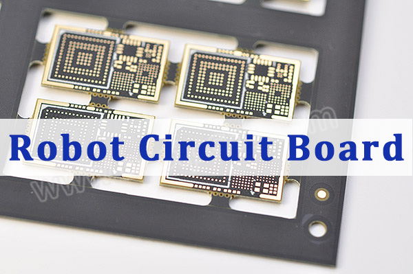
What Is a Robot Circuit Board and Why Is It the Brain of a Robot?
A robot circuit board—also referred to as a robotics circuit board or circuit board robot control system—is the electronic platform that integrates processing, sensing, actuation, communication, and power management into a unified system.
In functional terms, it performs five core tasks:
- Signal Acquisition – Reads data from sensors such as IMUs, encoders, cameras, ultrasonic modules.
- Processing and Logic Control – Executes firmware or embedded Linux control logic.
- Motor Drive Management – Controls PWM signals and current regulation for motors.
- Communication Handling – Manages CAN, UART, SPI, I²C, Ethernet, or wireless modules.
- Power Regulation – Converts battery voltage into stable rails (5V, 3.3V, 12V, etc.).
Without this central platform, a mechanical robot becomes an inert assembly of motors and sensors. The robotics circuit board synchronizes motion, maintains feedback loops, and enables autonomous behavior.
In advanced systems, multiple boards may be used:
- Main control board
- Motor driver board
- Vision processing board
- Power distribution board
Together, these form a distributed control architecture.
How to Make a Robot Circuit Board Step by Step?
If you’re planning to build a robot circuit board, the process follows professional PCB development methodology.
Step 1: Define Functional Requirements
Clarify:
- Number of motors
- Sensor types
- Communication protocols
- Battery type and voltage
- Required processing power
For example, a self-balancing robot demands fast IMU sampling and closed-loop motor control with minimal latency.
Step 2: Schematic Design
Using tools such as:
- Altium Designer
- KiCad
- Eagle
Define:
- Microcontroller or SoC
- Motor driver ICs
- Voltage regulators
- Connectors
- Protection circuits
Component placement decisions affect routing complexity later.
Step 3: PCB Layout
Key considerations when you make a robot circuit board:
- Separate analog and digital grounds
- Keep high-current motor traces short and wide
- Add copper pours for thermal dissipation
- Use differential routing for communication lines
For motor-heavy designs, consider 2oz or 3oz copper to support higher current loads.
Step 4: Prototyping and Fabrication
Choose:
- 2-layer board for simple robots
- 4-layer board for improved EMI control
- 6-layer board for high-speed systems
Step 5: Assembly and Testing
After fabrication:
- Perform visual inspection
- Power rail validation
- Firmware flashing
- Functional motor testing
- Sensor calibration
This completes the cycle of how to build a robot circuit board from concept to working hardware.
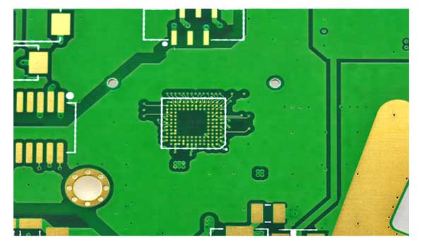
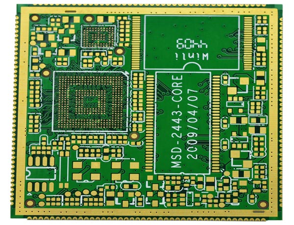
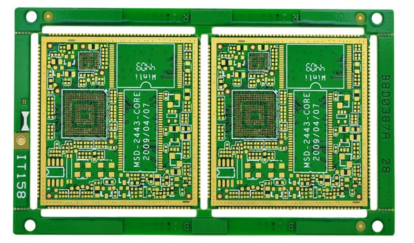
What Types of Circuit Boards Are Used in Robotics Applications?
Different robotics systems require different board structures. Selecting the right PCB structure ensures mechanical durability and electrical stability.
1. Single-Layer PCB
Used for:
- Simple robot kits
- Educational platforms
- Low-current applications
2. Multi-Layer PCB
Common in:
- Autonomous vehicles
- Drone flight controllers
- AI-enabled robots
4-layer structure is typical:
- Top layer: signal
- Inner layer 1: ground
- Inner layer 2: power
- Bottom layer: signal
3. HDI (High-Density Interconnect)
Used for compact robot vision circuit boards and embedded AI modules.
Features:
- Microvias
- Fine pitch BGA support
- Reduced form factor
4. Flexible PCB
Applied in:
- Robotic eye circuit board modules
- Articulated robotic arms
- Compact camera assemblies
5. Heavy Copper PCB
Required for:
- High-current motor drivers
- Industrial robotic platforms
- Power distribution modules
A well-designed robotics circuit board balances layer count, copper thickness, and thermal strategy.
What Circuit Board Is Used for Robotic Vehicles?
A circuit board for robotic vehicle applications must support mobility, feedback control, and real-time processing.
Typical architecture includes:
- MCU or embedded Linux processor
- Motor driver stage (H-bridge or BLDC controller)
- IMU module
- Encoder inputs
- Battery management
For a circuit board for self balancing robot, the board must:
- Process gyroscope data rapidly
- Maintain tight control loop timing
- Provide stable 5V and 3.3V rails
- Isolate motor noise from signal circuits
A robotic vehicle circuit board often integrates:
- CAN communication
- Obstacle detection sensors
- Wireless telemetry
Layer count: usually 4-layer minimum to control EMI and power integrity.
How to Design and Simulate a Robotic Vehicle Circuit Board?
Before manufacturing, simulation reduces design risks.
Electrical Simulation
Using tools like:
- Proteus (for proteus simulation robotic vehicle circuit board)
- LTspice
- Multisim
Engineers simulate:
- Power rail stability
- Motor driver switching behavior
- Sensor input filtering
Control Simulation
For robotics logic:
- MATLAB/Simulink
- ROS-based testing
Simulation helps verify:
- PID loop stability
- Noise filtering
- Communication timing
A proper simulation circuit board for robotic vehicle stage avoids costly re-spins.
Where Does the Circuit Board Go in a Robot?
Board placement depends on mechanical design and system architecture.
1. Main Control Board
Mounted centrally for weight balance.
2. Motor Driver Board
Placed close to motors to reduce current path length.
3. Power Board
Located near battery pack.
4. Vision or Sensor Board
Often positioned at the front or elevated for better field of view.
In drones, the control board sits at the geometric center to maintain stability.
Thermal considerations:
- Provide airflow
- Avoid enclosing high-power driver boards tightly
- Use mounting holes with proper grounding
To conclude, a robot circuit board is the foundation of robotic intelligence. From simple educational kits to complex autonomous vehicles, board architecture determines electrical stability, control accuracy, and long-term reliability.
Designing the right robotics circuit board requires structured planning, correct material selection, simulation validation, and precise assembly execution. When engineered properly, the board transforms mechanical hardware into a responsive, intelligent system capable of real-world performance.
If you are developing a circuit board for robotic vehicle platforms or advanced robotic applications, a carefully designed and professionally assembled solution will significantly reduce development cycles and enhance product stability. For engineering support or a project quotation, contact us at +86-755-2909-1601 or sales@bestpcbs.com.
FAQs About Robot Circuit Boards
1. What is the best PCB material for robotics?
FR-4 is most common due to cost efficiency and mechanical stability. For high-frequency or compact vision systems, advanced materials may be used. For high-power robotics, thick copper FR-4 is often sufficient.
2. How much does a robotics circuit board cost?
Cost depends on:
- Layer count
- Copper thickness
- Board size
- Assembly complexity
Simple 2-layer boards can be low cost in prototype quantities. Multi-layer industrial boards cost more due to fabrication precision and assembly requirements.
3. What layer count is typical for robotic control boards?
- Educational robot: 2 layers
- Hobby drone: 4 layers
- Industrial robot controller: 6 layers or more
Higher layers improve EMI control and signal routing density.
4. How do I test a robot circuit board after assembly?
Standard validation includes:
- Continuity and short-circuit testing
- Power-on voltage measurement
- Firmware upload verification
- Motor load testing
- Sensor calibration
- Functional movement validation
For professional manufacturing, AOI, ICT, and functional testing are recommended.