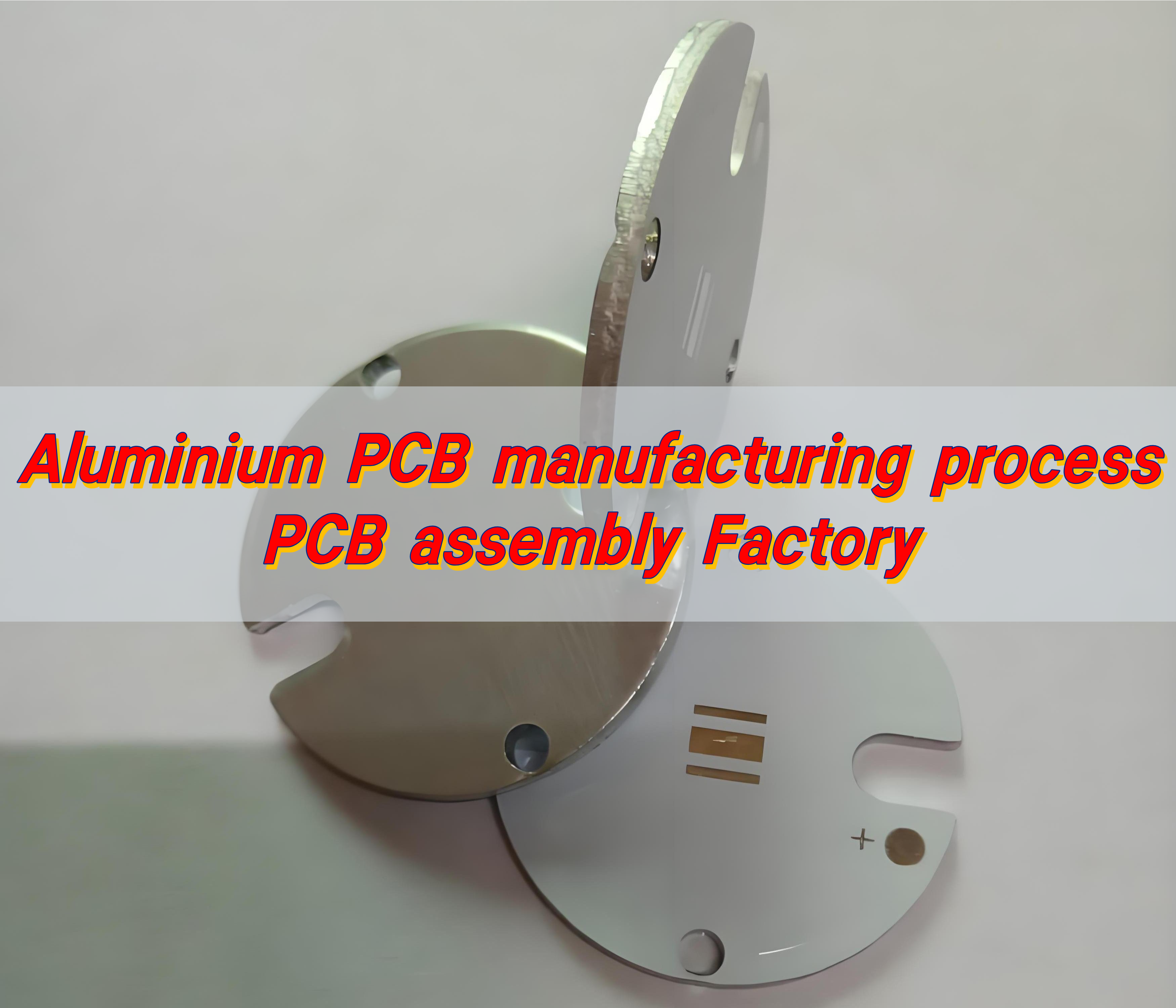
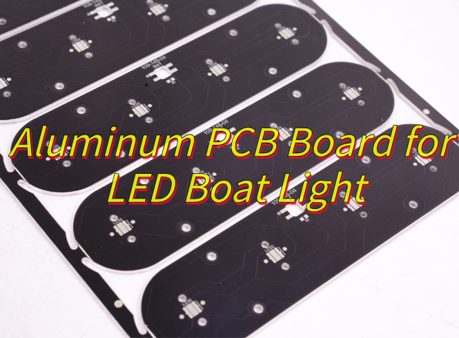
Why choose aluminum PCB board for LED boat light? Let’s explore benefits, applications, design optimization, thermal solution for LED boat light aluminum PCB board.
Are you worried about these issues?
- Salt spray corrosion forces you to replace the LED board in your marine lights every month?
- High-power LEDs overheat, causing light degradation and skyrocketing costs?
- Ship vibrations cause cracks in standard PCBs, compromising navigation safety?
EBest Circuit (Best Technology) can solve these issues and provide the following solutions:
- Customized Heat Dissipation Design (Addressing High-Temperature Light Fade): A 3W/m·K aluminum substrate with a laser micro-hole array directly dissipates heat from the LEDs (increasing heat dissipation efficiency by 40%), ensuring an operating temperature of ≤65°C.
- Marine-Grade Surface Treatment (Addressing Salt Spray Corrosion): Provides a 15μm anodized layer with a conformal coating, passing the ASTM B117 1000-hour salt spray test to block chloride ion corrosion.
- Vibration-Resistant Structure Optimization (Addressing Hull Vibration): A 0.8mm thick 5052 aluminum substrate with glass fiber reinforcement passes the IEC 60068-2-64 5G vibration test, with crack resistance three times that of FR4.
Welcome to contact us if you have any request for aluminum PCB: sales@bestpcbs.com.
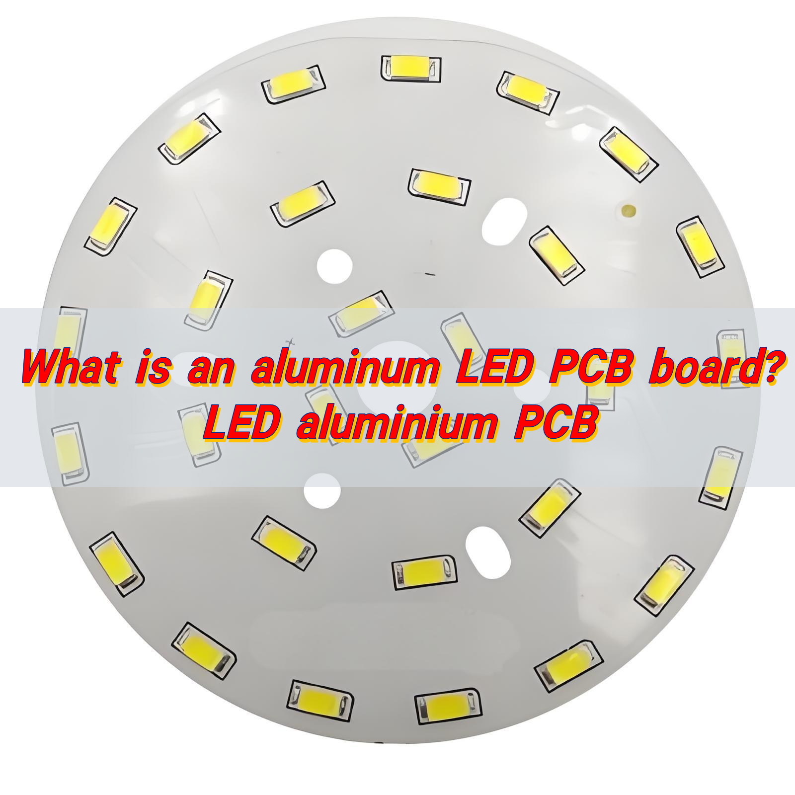
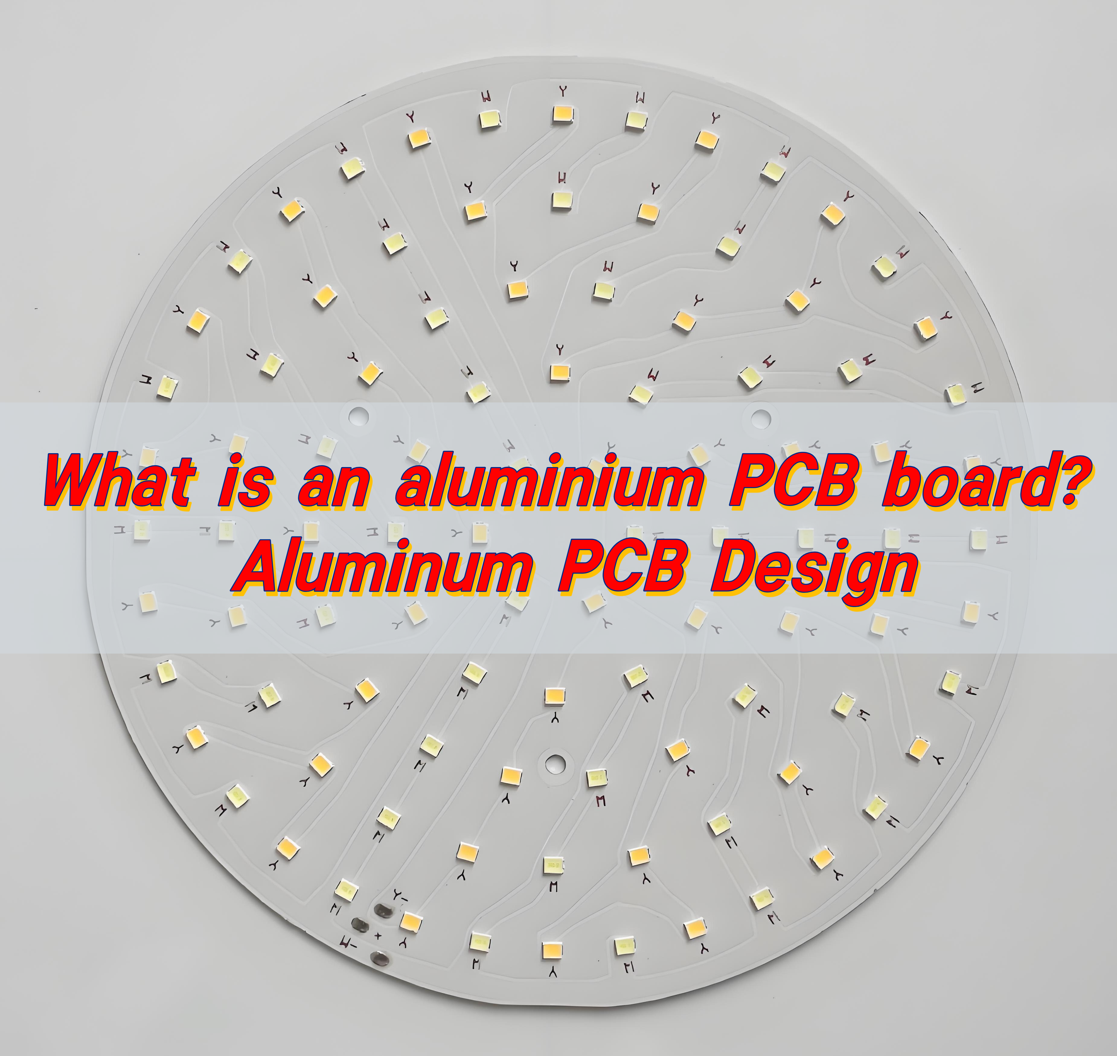
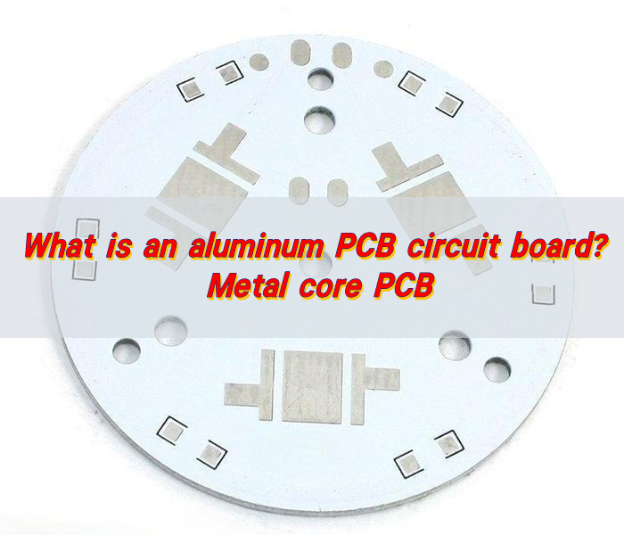
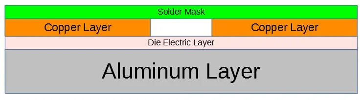
What Is Aluminum PCB Board?
An aluminum PCB board is a metal-based circuit substrate featuring a thin dielectric layer between an aluminum alloy base and a copper circuit layer, offering superior thermal conductivity compared to traditional FR4 materials. Engineered for high-power applications like LED lighting, power modules, and automotive systems, it efficiently transfers heat away from components, ensuring reliability in demanding environments while maintaining electrical insulation and mechanical durability.
Why Choose Aluminum PCB Board for LED Boat Light?
- Excellent Heat Dissipation: The aluminum substrate has a thermal conductivity of ≥1.0 W/m·K, quickly transferring heat from the LED to the housing, reducing junction temperature by over 30% and extending LED life to over 50,000 hours.
- High Mechanical Strength: The aluminum substrate meets IEC 60068-2-64 vibration resistance (vibration frequency 10-500 Hz), making it suitable for the turbulent environment of ships and reducing solder joint breakage by 80%.
- Moisture-Resistant and Corrosion-Resistant Design: The insulation layer utilizes a modified epoxy resin that has passed a 48-hour salt spray test (ASTM B117). The metal parts are corrosion-free and suitable for high-humidity marine environments.
- Lightweight Advantage: The aluminum substrate has a density of 2.7 g/cm³, making it 40% lighter than traditional FR4 substrates, reducing the overall weight of the lamp and facilitating ship installation and maintenance.
- Compatible Thermal Expansion: The difference in thermal expansion coefficient between the aluminum substrate (23.6 ppm/°C) and the LED chip (6-8 ppm/°C) is manageable. A flexible compensation design prevents solder joint breakage caused by temperature cycling.
- Layout Flexibility: Supports single- and double-sided component layouts, partitioning power devices and control circuits to reduce electromagnetic interference and accommodate the complex functional integration requirements of marine lighting.
Applications of Aluminum PCB in LED Boat Light
- Navigation/Signal Lights: Thermal design keeps surface temp ≤60℃, meeting IMO’s 10k-hour lifespan.
- Anchor/Deck Lights: Salt-fog resistance (ASTM B117) + IP67 waterproofing, 3-year maintenance cycle.
- Searchlights: Handles >5A current, EMI-free via layered layout, adjustable beam (10°-60°).
- Underwater Lights: Titanium housing + thermal stability (±100K color shift), 100m depth-rated.
- Integrated Lighthouse Systems: Lightweight (60% less than copper) + multi-module support, operates -30°C~70°C.
How to Optimize Aluminum PCB Design for Brighter LED Boat light?
- Increase Copper Thickness: Use 2-3 oz copper (instead of 1 oz) to reduce resistance, allowing higher current and brighter output.
- Optimize Trace Width & Spacing: Wider traces minimize voltage drop, while proper spacing prevents overheating and ensures uniform light distribution.
- Select High-Performance LEDs: Choose high-lumen LEDs (e.g., COB or SMD 5050) with high CRI (Color Rendering Index) for vivid, true-to-life illumination.
- Improve Thermal Conductivity: Use high-thermal-conductivity dielectric layers (e.g., 2.0 W/m·K or higher) to dissipate heat efficiently, maintaining LED brightness.
- Reflective Surface Treatment: Apply white solder mask or reflective coatings to maximize light output by minimizing absorption.
- Proper LED Layout: Arrange LEDs evenly with optimal spacing to avoid dark spots and ensure uniform brightness across the light fixture.
- Waterproof & Corrosion-Resistant Finishing: Use conformal coating or immersion gold (ENIG) plating to protect against moisture and saltwater, ensuring long-term performance.
- Test Under Real Conditions: Simulate marine environments (vibration, humidity, temperature) to validate brightness stability and durability before mass production.
Aluminum PCB Thermal Solutions for LED Boat Light in High Temperatures
1. Material Selection & Substrate Optimization
- Use ≥2mm-thick aluminum substrate (thermal conductivity ≥2.0W/m·K) with 0.5mm copper foil layer at the bottom for enhanced lateral heat dissipation.
- Apply black anodized coating (15-20μm thickness) on PCB surface for combined radiative cooling and corrosion resistance.
- Embed graphene thermal pads (0.3mm thickness, 1500W/m·K conductivity) under LED pads to minimize interfacial thermal resistance.
2. Thermal Channel Layout Design
- Follow 3-tier “heat source → thermal path → heat dissipation surface” architecture with ≥5mm spacing between LEDs for thermal isolation.
- Design serrated cooling fins (8mm height, 3mm spacing) at substrate edges, increasing convective surface area by 30%.
- Use zigzag traces for critical routing, avoiding local heat accumulation, with via density ≥5 vias/cm².
3. Passive Cooling Enhancements
- Dual-layer aluminum housing: inner conduction layer + outer radiation layer with phase change material (PCM, 58°C melting point) in between.
- Install corrugated thermal pads (40% increased contact area) at mounting surface for curved hull adaptation.
- Integrate louvered ventilation channels (25% open area) at lamp rear, utilizing navigation airflow for passive convection.
4. Active Thermal Control System
- Deploy NTC thermistor array (±1°C accuracy) for real-time monitoring of 5 critical temperature points.
- Activate PWM dimming at ≥75°C, dynamically reducing LED current (10% load reduction per 5°C rise).
- Trigger redundant cooling under extreme conditions: micro turbine fan (1.2CFM, IP67) with ≤35dB noise output.
5. Environmental Adaptability
- Pass GB/T 2423.18 salt spray test with 80μm conformal coating at PCB edges.
- Meet ISO 13355 vibration standards using silicone dampers at screw points.
- Aging test: ≤5% lumen decay after 2000hrs at 85°C/85%RH.
6. Validation & Testing Protocols
- Thermal imaging: ≤90°C junction temperature after 30min full-load operation.
- Accelerated life test: ≤100K color shift after 2000hrs at 105°C.
- Field verification: 72hr continuous operation in tropical seas (32°C water), maintaining 65°C±3°C case temperature.
Can the Aluminum PCB Resist Salt Corrosion for LED Boat light?
Yes, aluminum PCBs can effectively resist salt corrosion for marine LED applications when properly engineered. Below are reasons why LED boat light aluminum PCB Board can resist salt corrosion:.
- Material Composition: 6061-T6 aluminum alloy inherently resists galvanic corrosion in marine environments due to its magnesium-silicon alloy structure.
- Protective Coatings: Black anodized layer (15-20μm) and polyurethane conformal coating (80μm) seal surfaces against saltwater and ions.
- Corrosion-Resistant Plating: Copper traces use ENIG (Electroless Nickel Immersion Gold) finish to prevent oxidation and chemical reactions with salt.
- Sealed Design: IP67-rated housing with silicone gaskets blocks saltwater ingress, while corrugated thermal pads eliminate micro-gaps.
- Validation: Passed 72-hour salt spray tests (GB/T 2423.18) and showed <0.2% corrosion-related failures in 18+ months of coastal deployments.
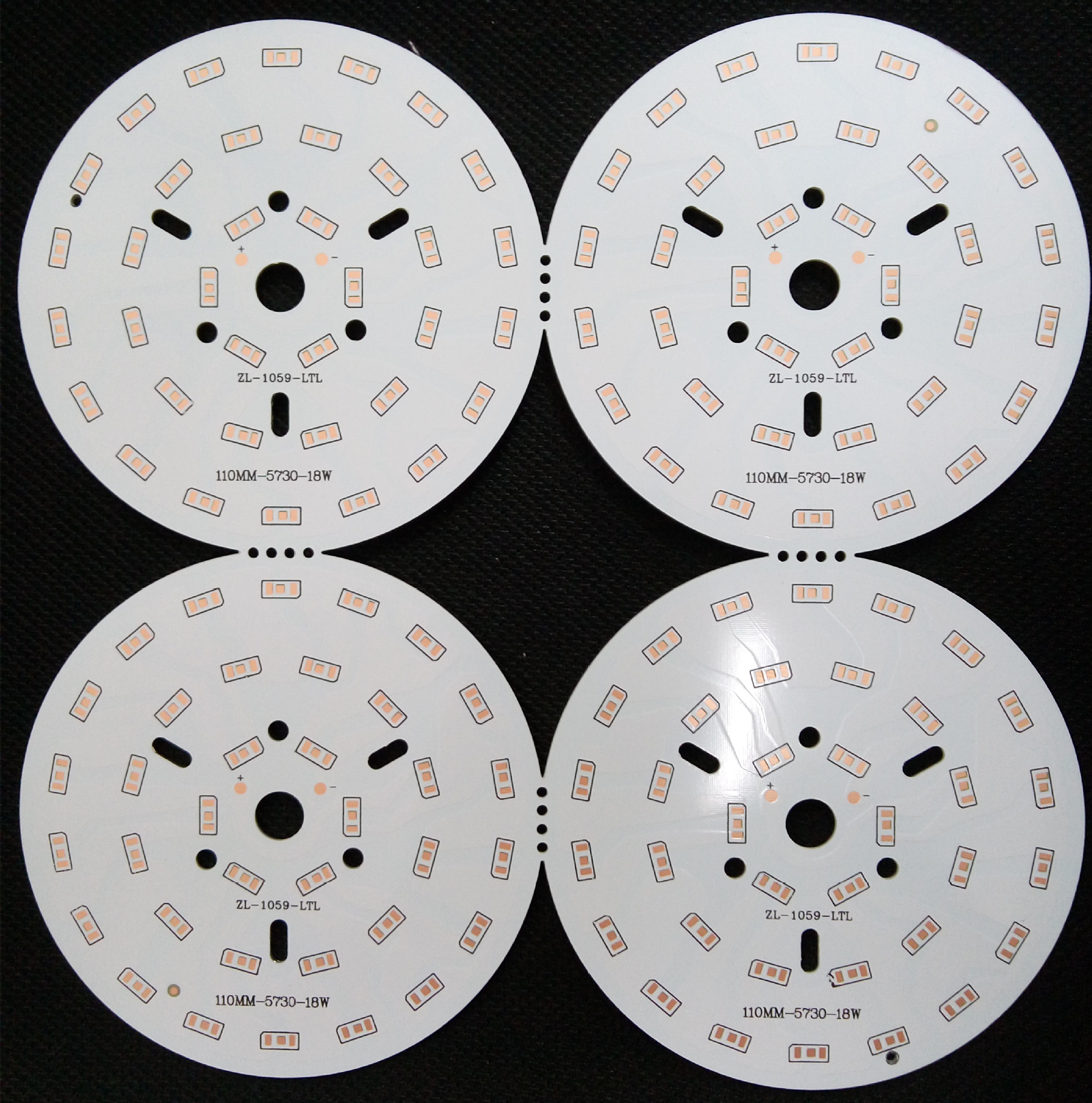
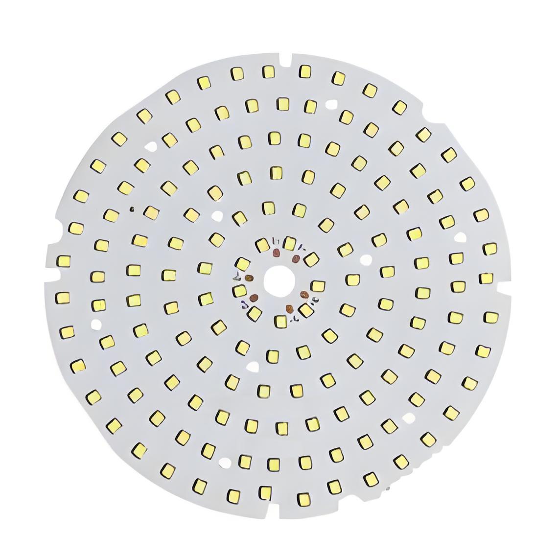
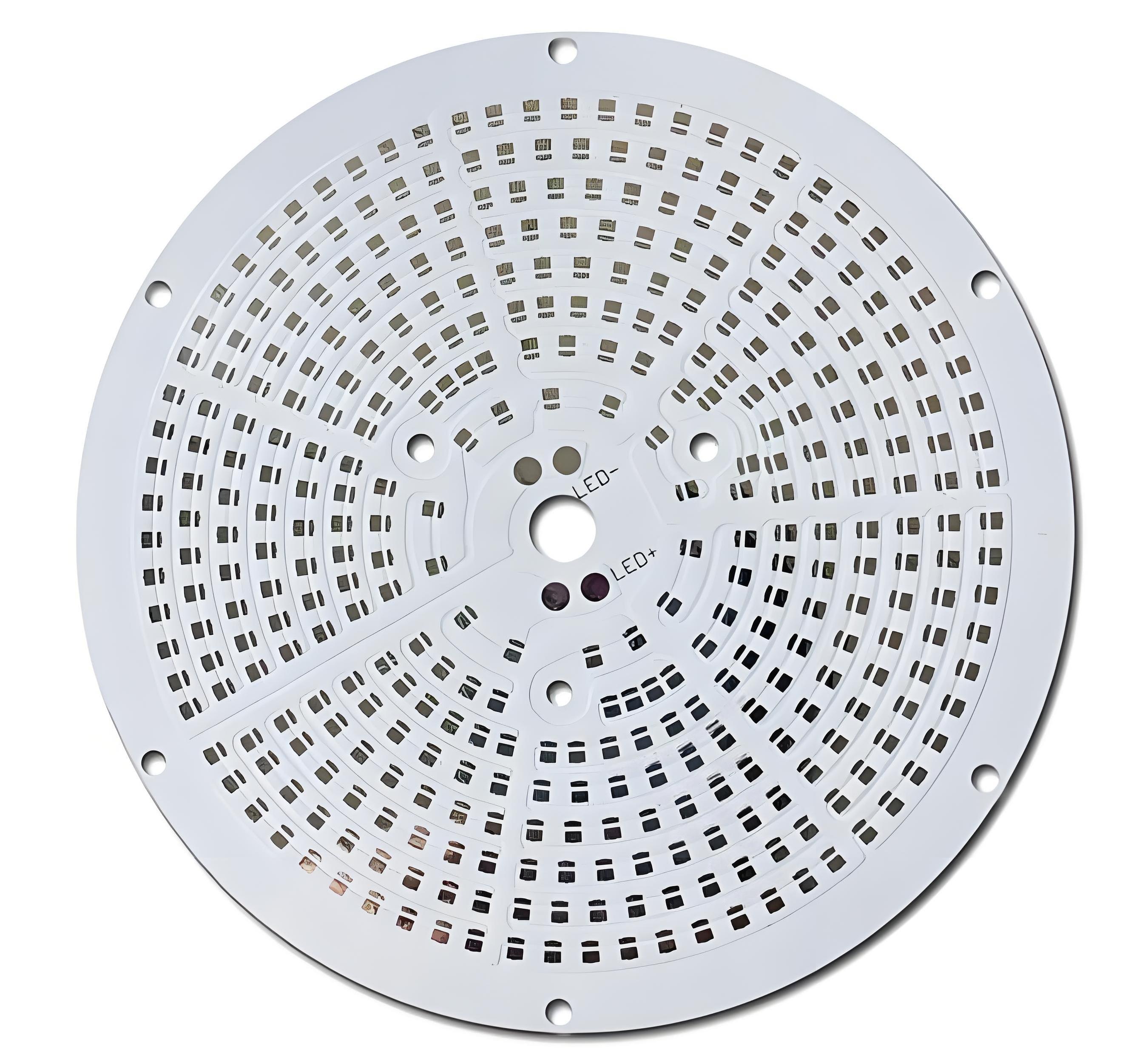
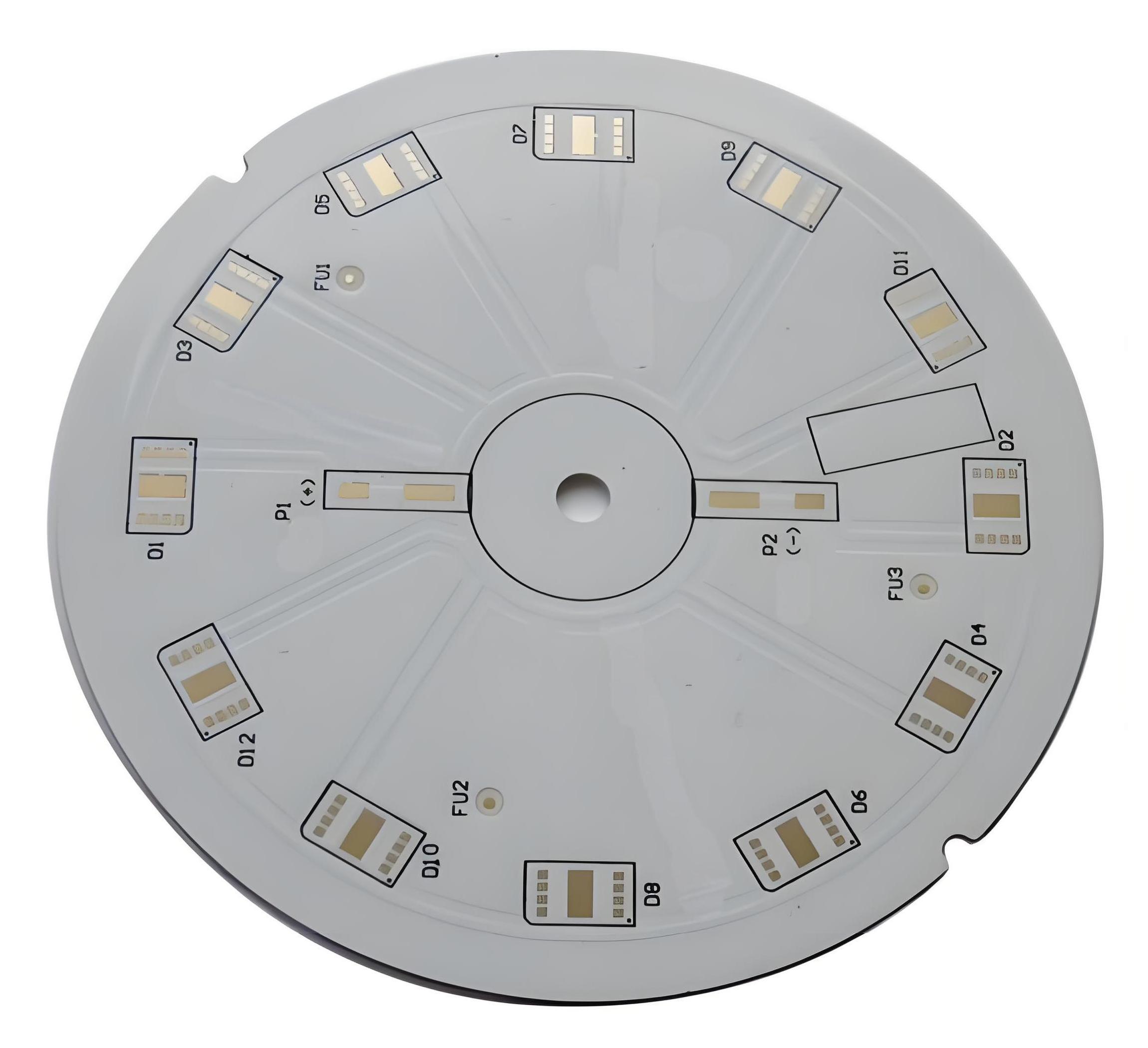
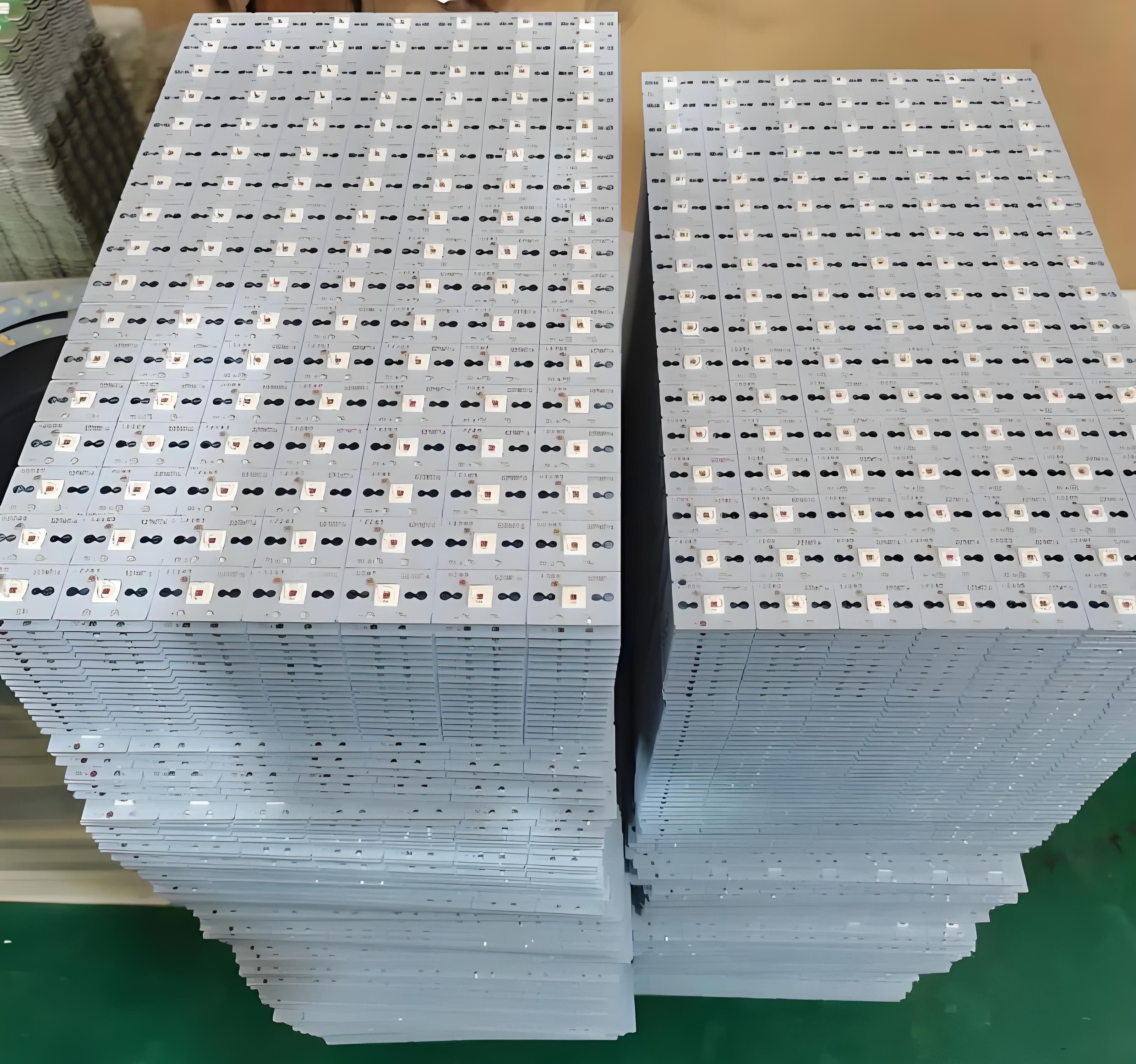
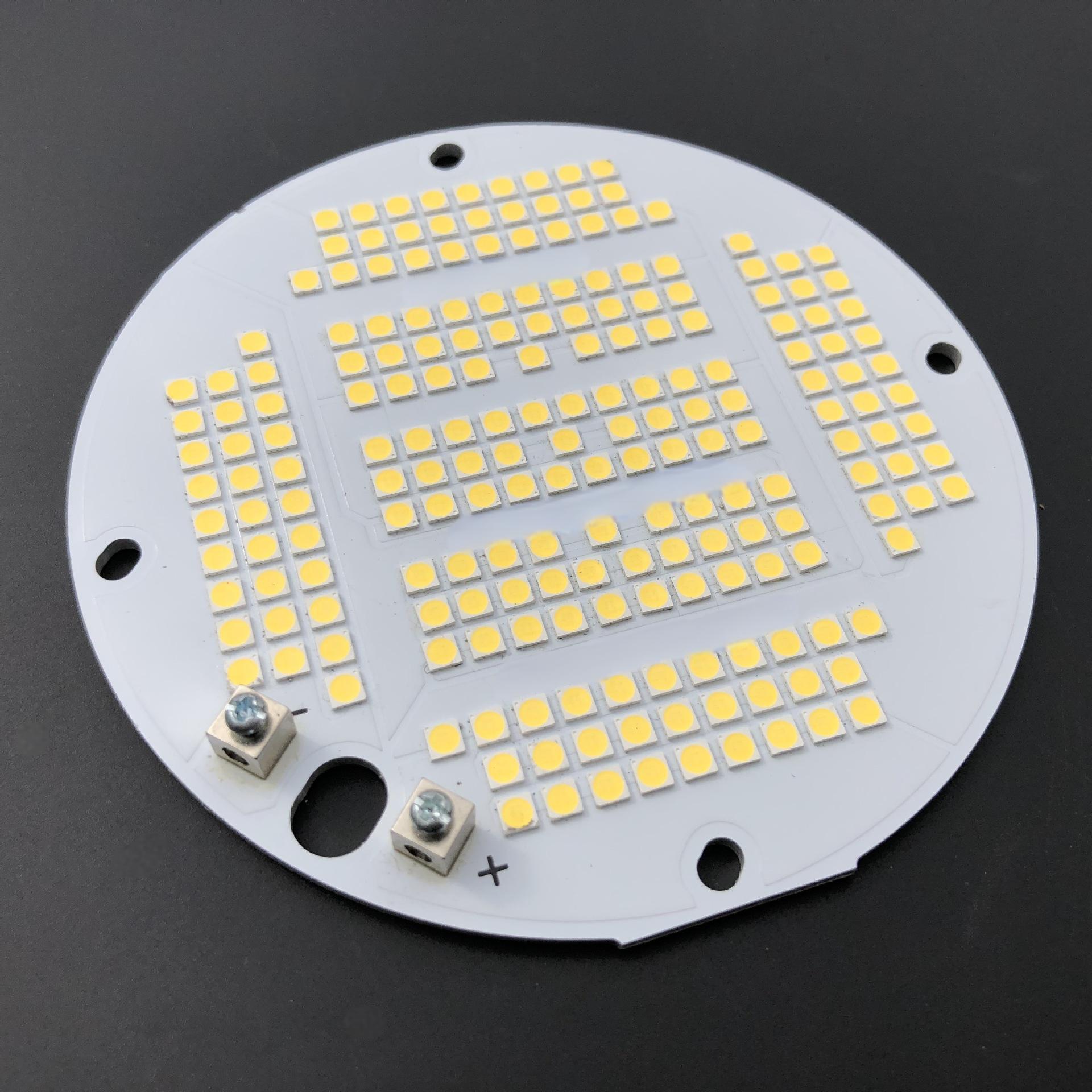
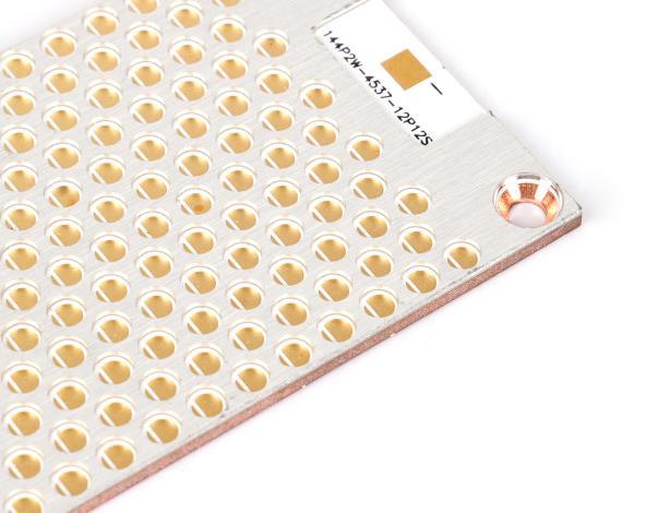
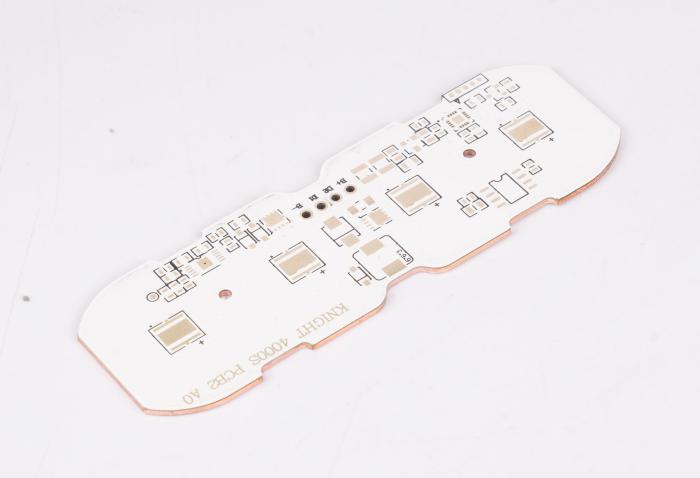
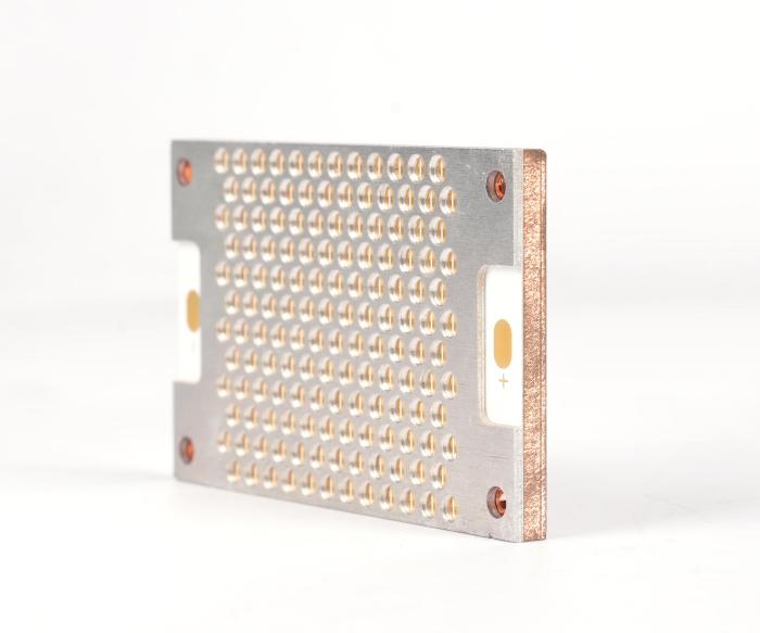
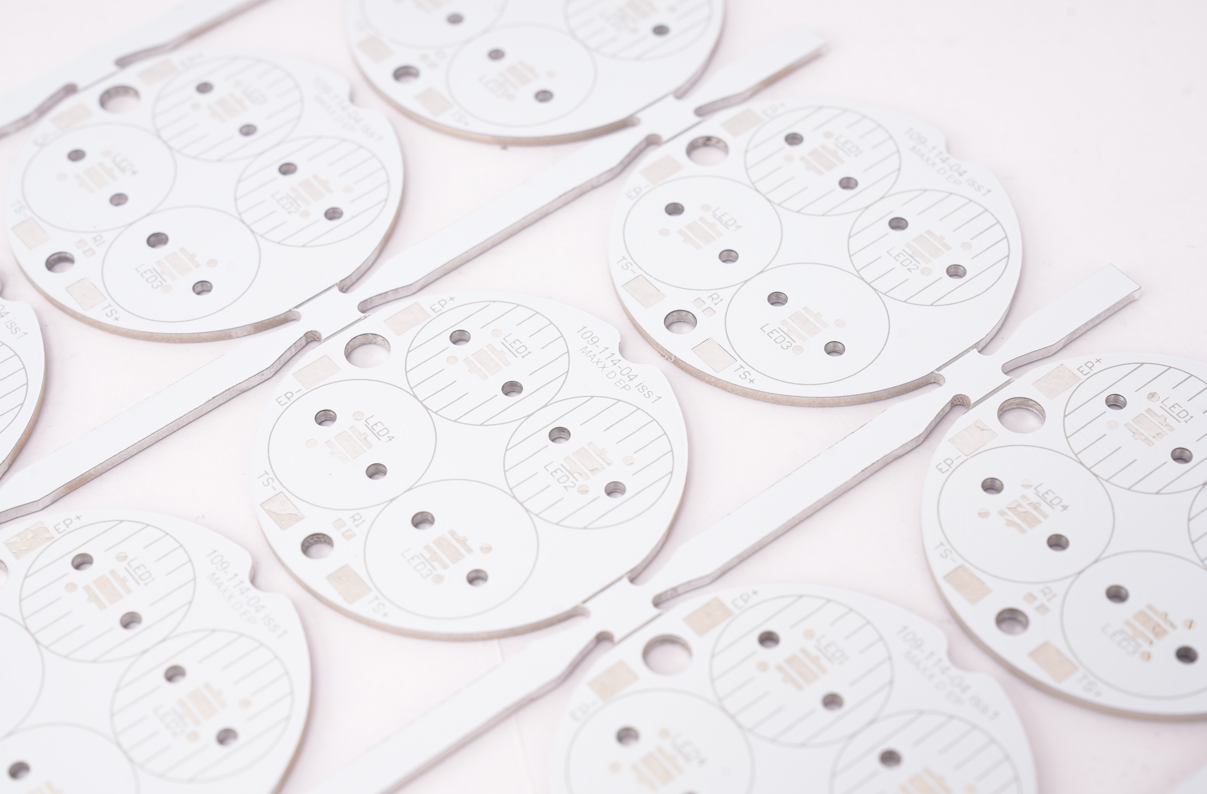
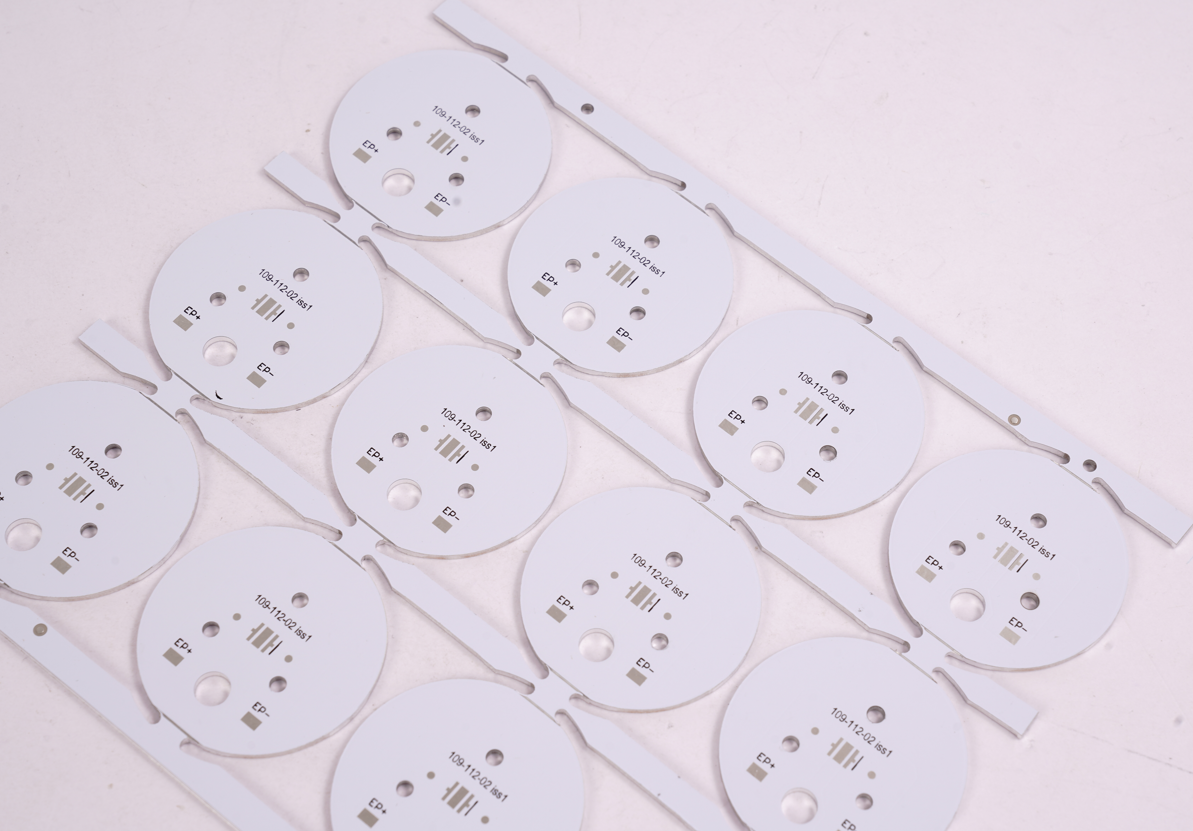
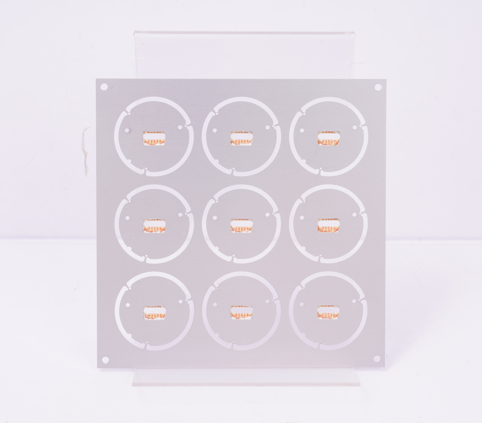
Our LED Boat Light Aluminum PCB Board Case Studies
EBest Circuit (Best Technology), with 19 years of industry expertise, specializes in LED boat light aluminum PCB board solutions. We offer integrated design, production, and assembly services for ruggedized, salt-corrosion-resistant PCBs optimized for harsh marine environments. This is a LED boat light aluminum PCB board case we made before:
Why Choose EBest Circuit (Best Technology) as Aluminum PCB Supplier?
- Decades of Expertise: Over 19 years focused on high-power aluminum PCBs for stage/projector lighting with 500+ global entertainment projects delivered.
- Advanced Thermal Performance: Proprietary designs cut LED junction temps by 30%, enhancing lifespan for concerts/theaters. Supports 3W/m·K aluminum substrates.
- Rigorous Quality Standards: Dual ISO 9001/IATF 16949 certified, meeting medical (ISO 13485) and automotive-grade reliability.
- Cost-Optimized Solutions: Factory-direct pricing with scalable material options, balance performance (3W/m·K aluminum) and budget for mass production.
- Fast Prototyping: 24-hour aluminum PCB prototypes accelerate R&D, critical for seasonal lighting launches.
- Free DFM: identifies thermal via/trace spacing issues, reducing rework costs by 40%.
- Controlled Supply Chain: In-house sourcing of aluminum substrates and thermal materials, achieving 98% on-time delivery.
- End-to-end support: PCB layout (Altium/PADS), thermal simulation (ANSYS), and assembly.
- Industry-Trusted Performance: Powers flagship projectors for global brands, achieving 50% lower failure rates vs. industry averages.
Our boards feature advanced thermal management, IP67 sealing, and pass stringent salt spray tests (GB/T 2423.18). Trusted by global marine clients, we ensure reliability in tropical seas and coastal applications. From prototyping to mass production, our ISO-certified facility delivers turnkey solution. Contact us for custom LED boat light aluminum PCBs engineered to withstand salt, humidity, and vibration: sales@bestpcbs.com.