PCB manufacturing PCB manufacturing
Home > Blog

aluminum pcb

LED Emergency Light Aluminum PCB – Solve Overheating for Power Outages
Friday, March 27th, 2026

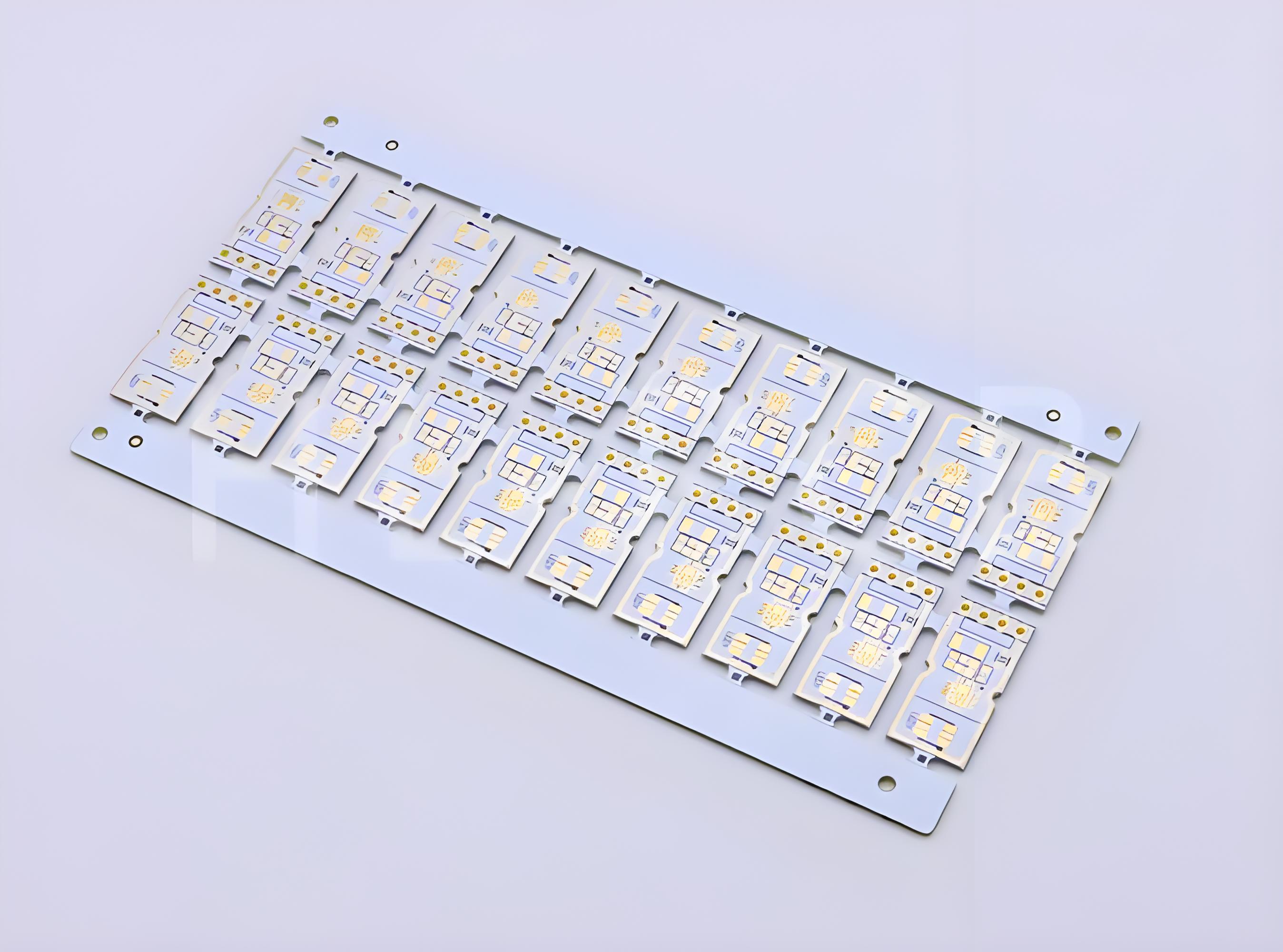
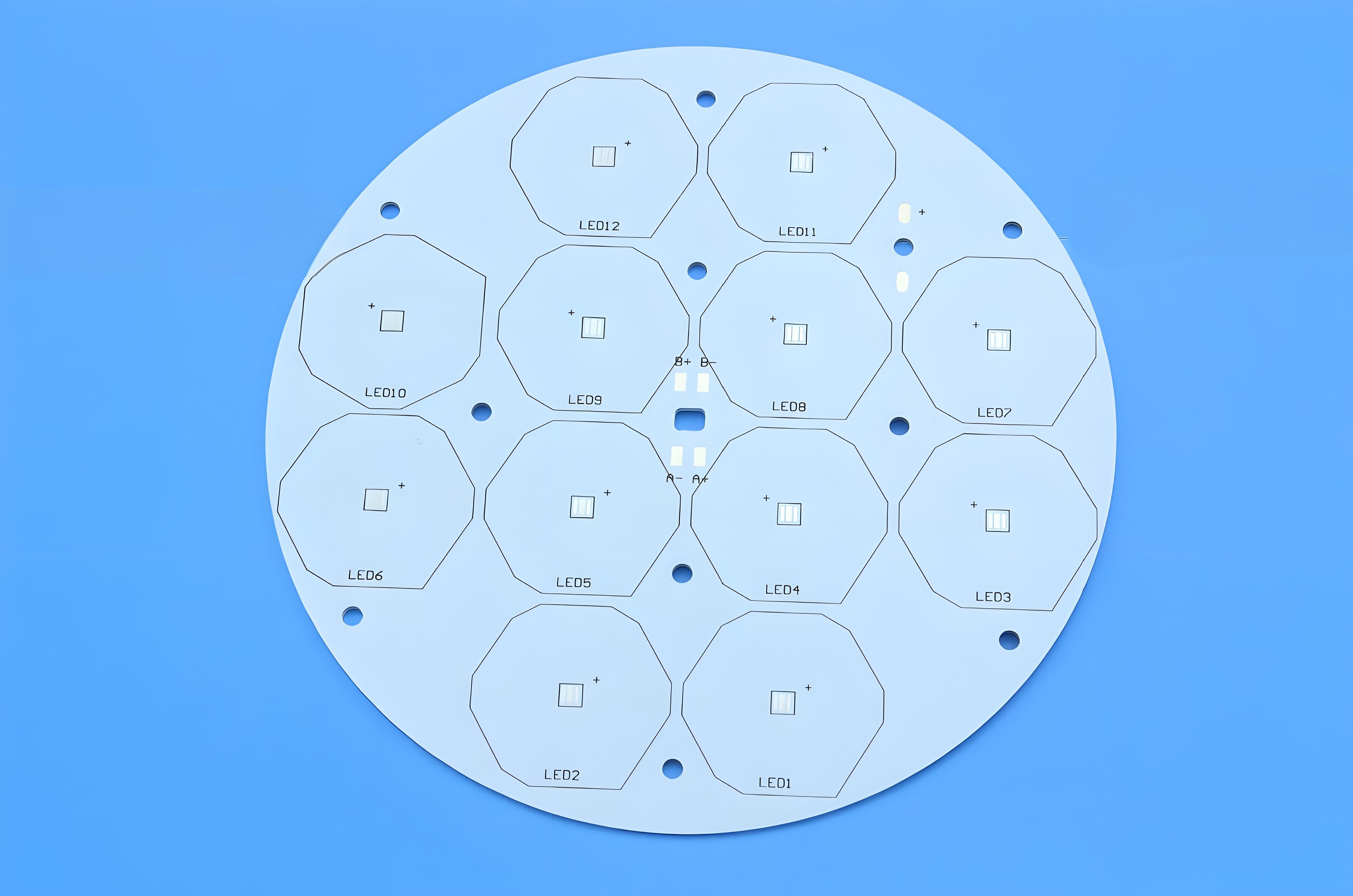
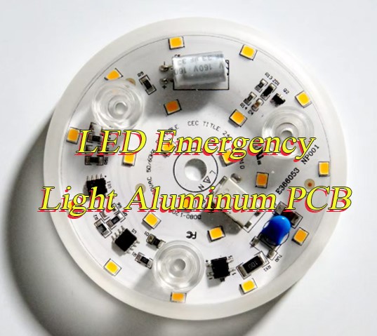
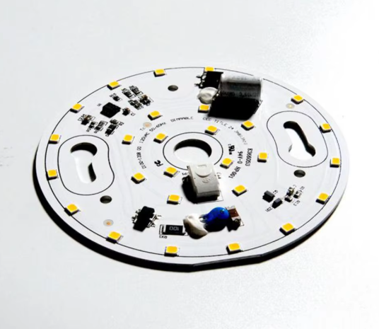
Is your LED emergency light aluminum PCB overheating during long standby, putting your emergency lighting system at risk of failure when power outages strike? Look no further than EBest for all your LED emergency light aluminum PCB needs.

We deliver uncompromising quality, fast lead times, optimized costs, professional service, and a stable supply chain, ensuring your emergency lighting systems perform flawlessly when you need them most. This blog breaks down common issues, solutions, and key considerations for LED emergency light aluminum PCBs, helping you make informed decisions.

LED Emergency Light Aluminum PCB, https://www.bestpcbs.com/blog/2026/03/led-emergency-light-aluminum-pcb/

Why Do LED Emergency Light Aluminum PCBs Overheat During Long Standby?

Two primary factors cause LED emergency light aluminum PCBs to overheat during long standby, both directly impacting performance and reliability.

One key cause is inefficient power management of the power supply unit (PSU). Even in standby mode, the PSU generates residual heat, which accumulates quickly without proper thermal design and leads to overheating. This buildup can degrade component performance over time and risk failure during power outages.

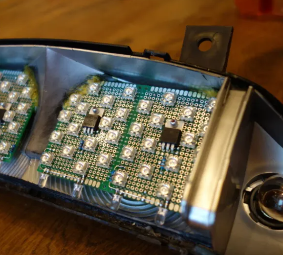
The other main cause is low-quality or improperly sized thermal dielectric layers. These layers transfer heat from the circuit to the aluminum base, so thin (e.g., 0.1mm) or low-grade materials fail to conduct heat effectively, creating hotspots. A hospital project we handled resolved overheating by upgrading from a 0.1mm to 0.2mm dielectric layer.

Overly thick dielectric layers also cause issues, as they increase thermal resistance and prevent efficient heat transfer, even with high-quality aluminum bases.

How Does LED Emergency Light Aluminum PCB Reduce Standby Energy Consumption?

LED emergency light aluminum PCBs reduce standby energy consumption through practical, engineer-verified design optimizations that deliver tangible energy savings for your emergency lighting systems. These optimizations focus on cutting unnecessary power waste while maintaining standby readiness.

The aluminum base’s superior thermal conductivity (far exceeding FR-4 PCBs) allows integration of smaller, low-static-current power supply units (PSUs) that generate less heat and use less power during standby. For a commercial building project, this design cut standby energy consumption by 35% compared to standard PCBs, directly reducing long-term energy costs for the client.

Optimized circuit routing further reduces energy waste by minimizing current leakage, a common source of standby power loss. We design traces to limit parasitic current, ensuring only essential power is used to keep the PCB in ready mode, without sacrificing emergency response speed.

How Does LED Emergency Light Aluminum PCB Reduce Standby Energy Consumption, https://www.bestpcbs.com/blog/2026/03/led-emergency-light-aluminum-pcb/

What Makes LED Emergency Light Aluminum PCB More Durable Than Regular PCBs?

LED emergency light aluminum PCBs outlast regular PCBs thanks to three core advantages that address common durability pain points for emergency lighting systems. These advantages ensure consistent performance even in harsh conditions, reducing replacement frequency and maintenance costs.

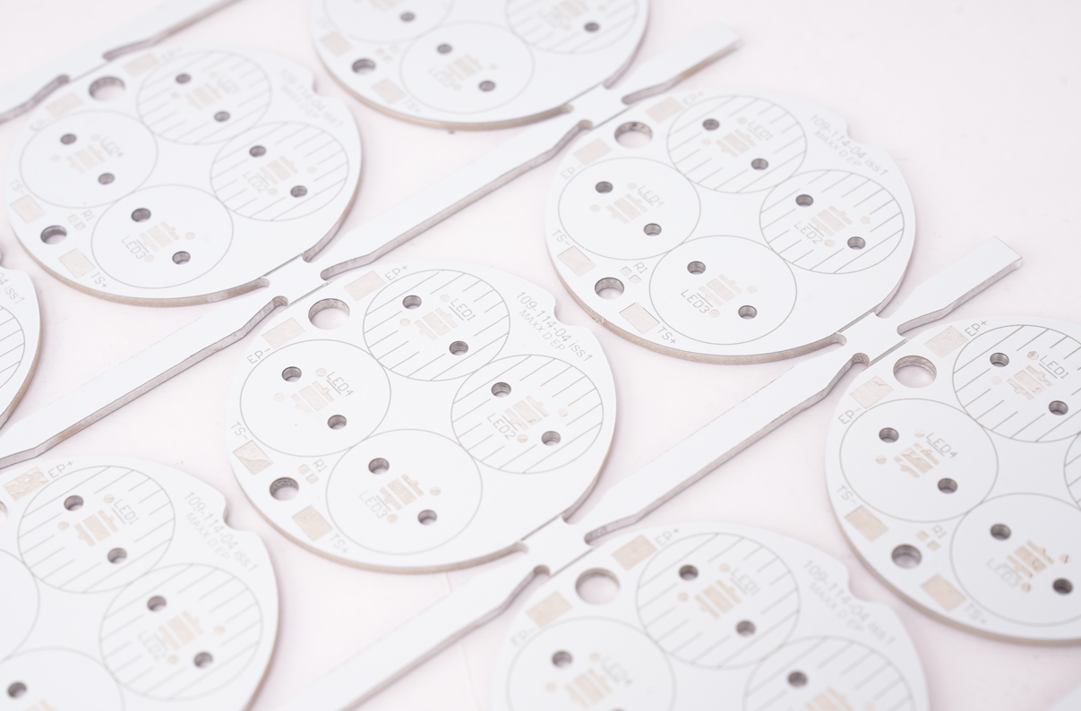
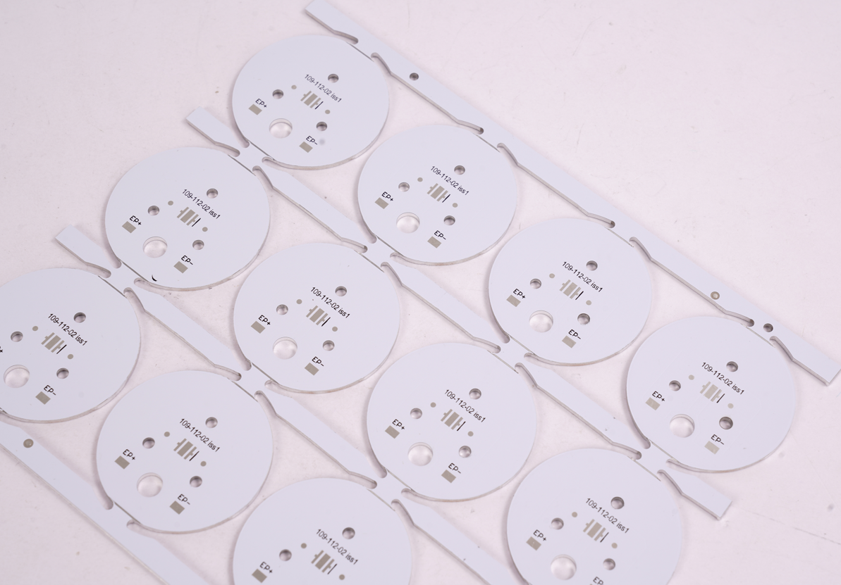
Superior mechanical strength from the aluminum base sets them apart. Unlike regular PCBs, the aluminum substrate resists bending, warping, and physical impact, critical for emergency lights installed in high-traffic or industrial areas. We use high-purity aluminum (99.5%+) or 5052 aluminum alloy for enhanced tensile strength, preventing damage from vibration or accidental contact.

Exceptional thermal stability ensures durability across extreme temperatures. Aluminum PCBs handle temperature fluctuations from -40ā„ƒ to 125ā„ƒ without degradation, while regular PCBs often warp or delaminate under such stress. Their balanced thermal expansion coefficients (CTE) between aluminum and copper minimize layer stress during heating and cooling cycles.

Reduced heat stress extends component and PCB lifespan. The aluminum base and high-quality dielectric layer efficiently dissipate heat, preventing component overheating that degrades regular PCBs. Our industrial clients report a 50% longer lifespan for aluminum PCBs in harsh factory environments, with minimal maintenance required.

How to Balance Heat Dissipation and Emergency Response with LED Emergency Light Aluminum PCB?

Balancing heat dissipation and emergency response for LED emergency light aluminum PCBs is critical to ensure long standby stability and rapid activation during power outages. Below are 8 specific measures to achieve this balance, each designed to optimize thermal performance without compromising emergency readiness.

  1. Use 2oz+ thickened copper traces: Thickened copper traces (2oz or higher) enable fast current flow during emergency activation, cutting response time to 0.2-0.5 seconds, while the aluminum base simultaneously dissipates standby heat to keep temperatures in check.
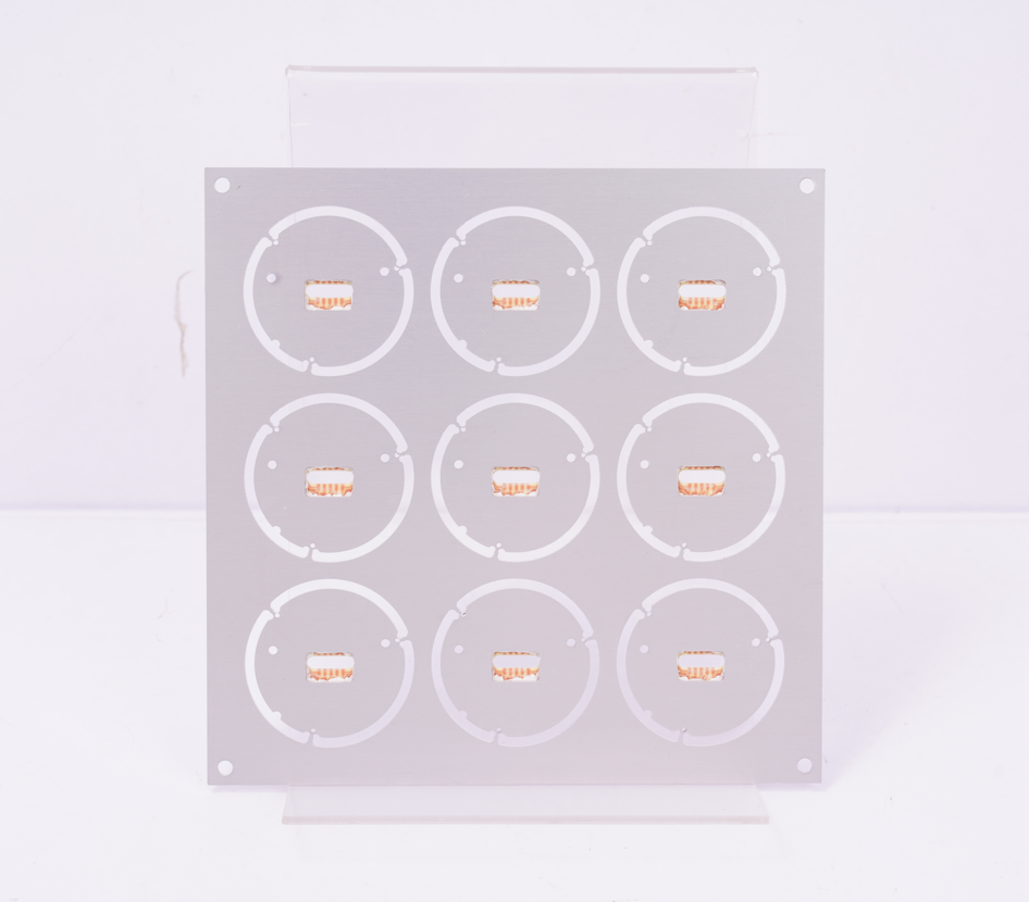
  2. Integrate dense thermal via arrays: Add thermal vias at a density of 8-12 per cm² to connect the circuit layer directly to the aluminum base, accelerating heat transfer without slowing down signal transmission during emergency mode.
  3. Select 0.15-0.2mm dielectric layers: Optimize for a 0.15-0.2mm thermal dielectric layer, this thickness balances thermal conductivity and insulation, ensuring efficient heat transfer from circuits to the aluminum base while preventing short circuits during rapid power delivery.
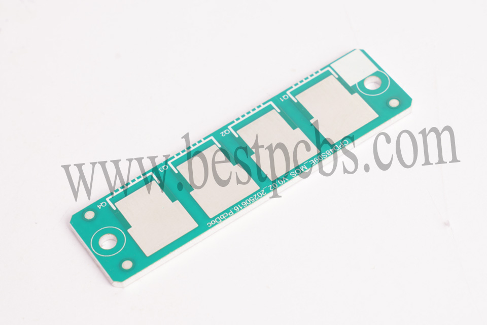
  4. Adopt PMOS tube for fast power switching: Use PMOS tubes as power switching components to enable seamless transition between standby and emergency modes, ensuring the PCB activates in under 0.5 seconds when power outages occur.
  5. Optimize component layout for thermal distribution: Place heat-generating components (e.g., PSU, LED drivers) near the aluminum base’s center for uniform heat dissipation, and keep emergency response components (e.g., switching chips) close to power sources to reduce signal delay.
  6. Integrate NTC thermal detection: Add NTC thermistors to monitor standby temperatures; if temperatures exceed 65ā„ƒ, the PCB automatically adjusts power output to reduce heat, while maintaining emergency response readiness.
  7. Choose high-purity aluminum base (99.5%+): Use high-purity aluminum (99.5% or higher) for the PCB base to enhance thermal conductivity, ensuring standby heat dissipates quickly without sacrificing the mechanical stability needed for reliable emergency operation.
  8. Implement low-power standby with rapid wake-up: Design the PCB for low-static-current standby to reduce heat generation, while integrating a rapid wake-up circuit that triggers full power delivery instantly when a power outage is detected, avoiding response delays.

What Thermal Conductivity Do LED Emergency Light Aluminum PCBs Need for Power Outages?

The thermal conductivity of LED emergency light aluminum PCBs directly determines their heat dissipation ability during power outages, which is key to ensuring stable emergency lighting. The optimal range for most applications is 1.5W/mĀ·K to 4.0W/mĀ·K, a balance of effective heat dissipation and cost-efficiency that avoids over-engineering or performance failures.

This range should be matched to your specific application scenario: for high-demand uses like industrial facilities, large commercial buildings or warehouses where emergency lights may run continuously for 4+ hours, 3.0W/mĀ·K to 4.0W/mĀ·K is required and we supplied 3.5W/mĀ·K PCBs for a warehouse project to ensure stable performance during extended outages. For low-demand applications such as residential hallways or small offices, 1.5W/mĀ·K to 2.0W/mĀ·K is sufficient to maintain reliable heat dissipation for short-term outages while keeping costs reasonable.

How to Ensure Quality Stability of LED Emergency Light Aluminum PCBs in Bulk Orders?

Ensuring quality stability of LED emergency light aluminum PCBs in bulk orders requires strict end-to-end control. Below are some measures to maintain uniform quality across all units without redundancy.

  • Strict raw material inspection: Test all aluminum substrates and dielectric layers for thermal conductivity, thickness and durability before production, complying with IPC-MF-150F standards to eliminate 60% of potential defects upfront.
  • Fix raw material suppliers: Use the same qualified supplier for each batch of raw materials, avoiding mixed vendors per lot to ensure consistent material performance and prevent quality fluctuations.
  • Hourly in-process SPC monitoring: Adopt Statistical Process Control (SPC) to monitor etching, lamination and drilling parameters hourly, keeping line width deviation within ±5μm for stable thermal performance.
  • Automated optical inspection (AOI): Use AOI systems to check circuit traces and solder joints during production, quickly identifying defects like trace misalignment to avoid batch quality issues.
  • 100% electrical and thermal final testing: Conduct full electrical and thermal testing on every unit, ensuring each PCB meets thermal conductivity and emergency response requirements before packaging.
  • Random reliability sampling tests: Perform random sampling tests (temperature cycling, humidity resistance) based on batch size, with 3-10 samples for different order scales to confirm long-term stability.
  • Batch tracing system: Establish a batch tracing system to record raw material lots, production parameters and test results, enabling quick troubleshooting if quality issues arise.
  • Pre-production prototype verification: Validate the PCB design with a prototype before bulk production, ensuring thermal and electrical performance meets requirements to avoid costly rework.
How to Ensure Quality Stability of LED Emergency Light Aluminum PCBs in Bulk Orders, https://www.bestpcbs.com/blog/2026/03/led-emergency-light-aluminum-pcb/

    Why Should LED Emergency Lights Use Aluminum PCBs Instead of FR-4 PCBs?

    Below is a detailed, concise comparison table helping you clearly understand why LED emergency lights should choose aluminum PCBs over FR-4 PCBs.

    Comparison DimensionAluminum PCBFR-4 PCB
    Heat Dissipation (Standby & Outages)1.5-4.0W/mĀ·K thermal conductivity for efficient heat transfer, preventing overheating during long standby/outages0.2-0.3W/mĀ·K thermal conductivity, poor heat dissipation leading to heat buildup and component failure risk
    Emergency Response Speed0.2-0.5 seconds activation for reliable, timely lighting during power cuts1.0-1.5 seconds activation with delays due to heat buildup, posing safety risks in emergencies
    Service Life & Maintenance50,000+ hours lifespan with minimal maintenance, reducing replacement frequency/costs20,000-30,000 hours lifespan requiring frequent replacements, increasing maintenance costs
    Mechanical Strength & DurabilityHigh-purity aluminum base resistant to bending, warping, and impact, suitable for harsh environmentsFragile material prone to warping/breaking, unsuitable for high-traffic/industrial areas
    Environmental AdaptabilityWithstands -40°C to 125°C, resists humidity/dust (IP65+ rated)Poor temperature adaptability, prone to delamination in humidity/extreme temperatures
    Long-Term Cost-EffectivenessHigher initial cost offset by lower long-term costs (no frequent replacements/extra cooling devices)Lower initial cost but higher long-term costs due to frequent replacements/maintenance

    How Does LED Emergency Light Aluminum PCB Improve Emergency Lighting Reliability?

    LED emergency light aluminum PCBs boost emergency lighting reliability by addressing the core causes of failure, ensuring consistent performance when power outages occur. Their design directly solves common issues that compromise emergency lighting readiness.

    They eliminate heat-related failures, the top cause of emergency light malfunctions. The aluminum base’s superior thermal conductivity dissipates standby heat, preventing component damage. For a hotel project, our aluminum PCBs reduced emergency light downtime by 70%.

    Stable thermal performance ensures even battery discharge in emergency mode, extending backup time by 20-30% compared to FR-4 PCBs. This guarantees lights stay on longer during outages, critical for safety and compliance.

    The aluminum base’s mechanical strength also prevents physical damage, while its thermal stability resists extreme temperatures (-40ā„ƒ to 125ā„ƒ), ensuring reliability in harsh environments like industrial facilities or cold storage.

    How Does LED Emergency Light Aluminum PCB Improve Emergency Lighting Reliability, https://www.bestpcbs.com/blog/2026/03/led-emergency-light-aluminum-pcb/

    What Are the Key Considerations When Choosing LED Emergency Light Aluminum PCB?

    When choosing LED emergency light aluminum PCBs, focus on these specific considerations to ensure compatibility, reliability and optimal performance for your emergency lighting system, each tip is practical and tailored to customer needs.

    • Match thermal conductivity to your application scenario: Select 1.5-2.0W/mĀ·K for low-demand uses (residential hallways, small offices) and 3.0-4.0W/mĀ·K for high-demand scenarios (industrial facilities, warehouses) to balance heat dissipation and cost-efficiency.
    • Optimize for 0.15-0.2mm thermal dielectric layers: This thickness balances thermal transfer and insulation, avoiding overheating from thin layers or poor heat conduction from overly thick layers, which is critical for long standby stability.
    • Choose 2oz+ thickened copper traces: Thickened copper traces ensure fast current flow (0.2-0.5 second activation) during power outages, preventing delayed emergency response and ensuring stable performance under load.
    • Prioritize high-purity aluminum base (99.5%+): High-purity aluminum enhances thermal conductivity and mechanical strength, resisting bending, warping and vibration—ideal for harsh or high-traffic installation environments.
    • Select appropriate surface finishing: Choose lead-free HASL, immersion gold or OSP surface finishing based on your needs: immersion gold for corrosion resistance, OSP for cost-effectiveness, and lead-free HASL for general-purpose use.
    • Verify board thickness compatibility: Optimize for 0.6-4mm board thickness, matching it to your emergency light fixture size, thicker boards for industrial use (3-4mm) and thinner ones (0.6-1mm) for residential or compact fixtures.
    • Ensure the supplier offers strict quality control: Partner with suppliers (like EBest) that conduct 100% electrical/thermal testing, AOI inspection and raw material verification to avoid batch defects in bulk orders.
    • Confirm customization capability: Choose a supplier that can customize thermal conductivity, dielectric thickness, trace width and size to fit your specific project, whether for hospitals, factories or residential buildings.

    FAQs About LED Emergency Light Aluminum PCB

    Q1: Can LED emergency light aluminum PCBs work in extreme cold environments?
    A1: Yes, LED emergency light aluminum PCBs work reliably in extreme cold (-40ā„ƒ). The aluminum base resists thermal contraction, and the dielectric layer remains stable, ensuring no performance loss. We supplied PCBs for a cold-storage warehouse that operates at -30ā„ƒ, with zero failures in 2 years.

    Q2: How long do LED emergency light aluminum PCBs last in standby mode?
    A2: LED emergency light aluminum PCBs last 50,000+ hours in standby mode, nearly twice as long as FR-4 PCBs. Proper maintenance (occasional cleaning of thermal surfaces) can extend this to 60,000+ hours.

    Q3: Do LED emergency light aluminum PCBs require special installation?
    A3: No, they do not require special installation. They are designed to fit standard emergency light fixtures, with the same mounting holes and circuit layout as FR-4 PCBs. This makes retrofitting easy and cost-effective.

    Q4: Can I customize LED emergency light aluminum PCBs for my specific project?
    A4: Yes, EBest offers full customization for LED emergency light aluminum PCBs. We can adjust thermal conductivity, dielectric thickness, copper trace width, and size to match your project’s unique needs, whether for hospitals, factories, or residential buildings.

    Q5: How do I test if my LED emergency light aluminum PCB is overheating?
    A5: Use a thermal imaging tool to check standby temperatures. A properly functioning LED emergency light aluminum PCB should stay below 65ā„ƒ. If temperatures exceed 70ā„ƒ, check the dielectric layer thickness or contact EBest for a design optimization.

    Motorcycle LED Light Aluminum PCB – High Thermal Conductivity for Outdoor Riding
    Thursday, March 26th, 2026

    Is your motorcycle LED light aluminum PCB reliable enough for outdoor riding? If you’re struggling with overheating, vibration damage, or short lifespans from your motorcycle LED light PCB, you need a solution you can trust. Choose EBest’s motorcycle LED light aluminum PCB, we deliver top-tier quality, on-time delivery, stable supply chains, and responsive service to solve all your outdoor riding lighting woes. This blog breaks down why aluminum PCBs are the best choice for motorcycle LEDs, how they solve common pain points, and where to get the best products for your project.

    Motorcycle LED Light Aluminum PCB, https://www.bestpcbs.com/blog/2026/03/motorcycle-led-light-aluminum-pcb/

    Why Choose Aluminum PCB for Motorcycle LED Lights?

    Aluminum PCBs are the optimal choice for motorcycle LED lights, as they’re engineered to tackle the harsh outdoor and off-road conditions that traditional PCBs struggle with. Their unique metal core design delivers unmatched thermal management, durability, and versatility, making them a reliable foundation for motorcycle lighting systems.

    • Exceptional thermal conductivity: Rapidly dissipates heat from LED chips, preventing burnout and extending light lifespan, critical for long rides and high-power LEDs.
    • Strong vibration resistance: Rigid aluminum base absorbs off-road shocks, keeping solder joints intact and avoiding component damage from rough terrain.
    • Compact, space-saving design: Thinner and lighter than FR4 PCBs, fitting easily into tight motorcycle light housings without sacrificing performance.
    • Waterproof-compatible: Works seamlessly with protective coatings (like IP67) to fend off rain, mud, and moisture, ensuring reliability in all weather.
    • Cost-effective durability: Reduces the need for extra cooling hardware, lowers long-term maintenance costs, and stands up to extreme temperature fluctuations (-40°C to 125°C).

    How Does High Thermal Conductivity Solve Motorcycle Light Overheating?

    Overheating is the top cause of LED failure in motorcycle lighting, especially during long outdoor rides or in extreme temperatures. LEDs are sensitive to heat, and excess warmth quickly leads to brightness dimming, premature burnout, and shortened lifespans.

    High thermal conductivity in motorcycle LED light aluminum PCB addresses this by acting as a heat conductor, rapidly transferring heat away from LED chips. Unlike traditional PCBs, aluminum’s core design ensures heat doesn’t accumulate around the LED components.

    Aluminum boasts a thermal conductivity of 200-237 W/mK, which is drastically higher than FR4 PCBs (0.2-0.4 W/mK). This gap means aluminum PCBs dissipate heat far faster, keeping LEDs within their optimal operating temperature range.

    By reducing heat buildup, Motorcycle LED Light Aluminum PCB prevents light decay and component damage. This not only extends LED lifespan by 30-50% but also ensures consistent brightness during long rides, critical for rider safety.

    The aluminum base also eliminates the need for extra cooling hardware, keeping motorcycle LED lights compact and lightweight, perfect for tight mounting spaces on bikes.

    Can Your LED Lights Handle Off-Road Vibration?

    Yes, Off-road riding exposes motorcycle LED lights to constant, intense vibration, far more than standard on-road use. This vibration is a major threat to PCB durability, as traditional PCBs often crack, have loose solder joints, or disconnect components after repeated exposure to rough terrain, leading to sudden light failure when you need it most.

    The solution lies in choosing a high-quality motorcycle LED light aluminum PCB. Unlike fragile traditional substrates, aluminum PCBs have a rigid, sturdy base that acts as a shock absorber, dampening vibration and keeping critical components secure. This inherent rigidity prevents the structural damage that plagues other PCB materials in off-road conditions.

    To ensure maximum reliability, EBest’s motorcycle LED light aluminum PCB undergoes strict vibration testing, adhering to industry standards with a frequency range of 10-2000Hz and 10g acceleration. This rigorous testing guarantees our PCBs hold up to even the harshest off-road trails, keeping your LED lights functional and your rides safe, no matter the terrain.

    Can Your LED Lights Handle Off-Road Vibration, https://www.bestpcbs.com/blog/2026/03/motorcycle-led-light-aluminum-pcb/

    Waterproof Riding Worries: Is Your Motorcycle Light PCB Protected?

    For outdoor and off-road riders, waterproof protection for your motorcycle LED light aluminum PCB is non-negotiable. Rain, mud, dew, and even pressure washing expose PCBs to moisture, which seeps into unprotected components and causes short circuits, leading to unexpected light failure when you need visibility most.

    Unlike traditional PCBs that struggle with moisture resistance, high-quality motorcycle LED light aluminum PCB is designed to work seamlessly with advanced waterproof coatings. EBest uses conformal coatings, thin, non-conductive polymer films that conform to the PCB’s shape, covering traces and solder joints to block out moisture effectively.

    Our PCBs meet IP67 waterproof standards, meaning they are dust-tight and protected against temporary submersion (1 meter depth for 30 minutes), passing rigorous testing that simulates heavy rain and off-road mud exposure. Sealed solder joints and durable coatings ensure your motorcycle LED lights stay functional, no matter the weather or terrain.

    Small Size, Big Power: How Do Aluminum PCBs Fit Tight Motorcycle Spaces?

    Motorcycle LED lights, whether headlights, turn signals, or auxiliary lights are designed to be compact, as motorcycle handlebars, fairings, and light housings have limited space. This means the Motorcycle LED Light Aluminum PCB inside must be small and lightweight, without sacrificing the performance needed for safe outdoor riding.

    Unlike traditional FR4 PCBs, aluminum PCBs have a unique three-layer structure (aluminum core between copper foil and dielectric layer) that eliminates the need for extra cooling components, which often add bulk. This streamlined design keeps the PCB thin while maintaining structural rigidity, a key advantage for tight mounting spaces.

    EBest’s motorcycle LED light aluminum PCB is engineered to a thickness of 0.8-1.2mm, 30% thinner than standard FR4 PCBs, making it easy to fit into slim light housings, even those with narrow internal dimensions like the compact copper housings used in high-power motorcycle headlights. This thin profile never compromises performance, as the aluminum core still delivers exceptional thermal conductivity.

    The compact design of aluminum PCBs also simplifies installation, especially for custom motorcycle LED projects. Their lightweight nature reduces strain on light mounts, and their slim profile fits seamlessly with the small wiring holes (often 7/64″ or smaller) common in motorcycle light housings, ensuring a clean, secure fit without modifying the bike’s existing setup.

    Long Rides, Reliable Lights: Does Your PCB Ensure Durability?

    For motorcycle riders, especially those who love long-distance or off-road adventures, PCB durability directly impacts riding safety and peace of mind. A faulty PCB can cause sudden LED light failure mid-ride, leaving you without critical visibility, which is why your motorcycle LED light’s PCB must be built to last as long as your bike.

    Unlike traditional FR4 PCBs that crack, warp, or fail under harsh conditions, motorcycle LED light aluminum PCB is engineered for long-term reliability. Its rigid aluminum core resists corrosion, wear, and the thermal stress caused by constant temperature changes, common issues that shorten the lifespan of other PCB materials.

    EBest’s motorcycle LED light aluminum PCB is rigorously tested to withstand extreme temperature ranges of -40°C to 125°C, making it suitable for all climates, from freezing mountain rides to scorching desert adventures. This wide temperature tolerance prevents insulation layer peeling or component damage, thanks to its well-matched thermal expansion coefficient with copper foil.

    Our customers consistently report an average lifespan of 5+ years for our PCBs, even with daily outdoor and off-road use. This durability eliminates the need for frequent replacements, saving time and hassle while ensuring your LED lights stay reliable, no matter how long or tough your rides are.

    Does Your PCB Ensure Durability, https://www.bestpcbs.com/blog/2026/03/motorcycle-led-light-aluminum-pcb/

    Cost vs. Quality: Finding the Best Value Aluminum PCB for LED Lights

    When sourcing motorcycle LED light aluminum PCB, balancing cost and quality is a top priority for most projects, overpaying for unnecessary features wastes budget, while cutting costs on critical components leads to frequent failures and higher long-term expenses.

    True value for motorcycle LED light aluminum PCB lies not in the lowest price, but in a combination of reliable performance, durability, and consistent supply. Opting for cheap, low-quality PCBs often results in overheating, vibration damage, or moisture issues, requiring costly replacements and project delays.

    EBest delivers this balance by optimizing every step of our manufacturing process from material selection to production efficiency to eliminate unnecessary costs, without compromising on quality. We source high-grade aluminum substrates and conduct strict quality checks, ensuring our PCBs meet the harsh demands of motorcycle riding.

    Our bulk supply capabilities further enhance value, offering stable pricing and on-time delivery for large projects. This consistency means you avoid unexpected cost hikes or delays, while getting a durable, high-performance motorcycle LED light aluminum PCB that delivers long-term reliability at a fair price.

    Extreme Weather Riding: Can Your LED Light PCBs Take the Heat and Rain?

    Extreme weather from scorching desert heat and heavy downpours to freezing mountain temperatures—poses a unique challenge for Motorcycle LED Light Aluminum PCB. Unlike on-road riding, outdoor and off-road adventures expose PCBs to unforgiving conditions that test their durability, and a subpar PCB will fail when you need reliable lighting most.

    When it comes to withstanding extreme heat, motorcycle LED light aluminum PCB outperforms traditional substrates by leaps and bounds. Its aluminum core, with a thermal conductivity of 200-237 W/mK, dissipates heat far faster than FR4 PCBs (which only have 0.2-0.4 W/mK), preventing LED overheating even in 100°F+ desert rides. This avoids component warping or solder joint failure that plagues low-quality PCBs in high temperatures.

    For heavy rain, mud, or even snowmelt, our Aluminum PCBs are paired with IP67-rated conformal coatings that seal every trace and solder joint. This protection blocks moisture from seeping into the PCB, eliminating short circuits and corrosion, common issues that render traditional PCBs useless after exposure to wet extreme weather.

    EBest’s Motorcycle LED Light Aluminum PCB also resists thermal shock, the sudden temperature changes that occur when riding from hot deserts to cold mountain passes. Its well-matched thermal expansion coefficient with copper foil prevents insulation peeling, ensuring consistent performance in all extreme weather, so your LED lights stay bright and reliable no matter the conditions. Unlike FR4 PCBs that have a thermal resistance of 20–22 °C per watt, our aluminum PCBs only have 1–2 °C per watt, making them far more resilient in harsh environments.

    Comparing PCB Materials: Why Aluminum Wins for Motorcycle LEDs

    PCB MaterialThermal Conductivity (W/mK)Vibration ResistanceWaterproof CompatibilitySuitability for Motorcycle LEDs
    Aluminum200-237HighExcellent (with coating)Best
    FR40.2-0.4LowPoorNot Recommended
    Copper401MediumGoodExpensive, Less Practical
    Flexible PCB1-2HighMediumLimited Thermal Performance

    Where to Find High-Performance Aluminum PCBs for Your Motorcycle LED Project?

    High-performance aluminum PCBs are critical for motorcycle LED systems, delivering superior heat dissipation, vibration resistance, and long-term reliability in harsh riding conditions. Whether building headlights, turn signals, accent lights, or high-power auxiliary LEDs, choosing the right source ensures stable performance, longer LED life, and compliance with automotive-grade standards. Below are targeted, actionable channels and suppliers to source reliable aluminum PCBs tailored to motorcycle LED projects.

    • Specialized Automotive & LED PCB Manufacturers: Focused vendors with IPC-A-600 Class 2/3 certification, optimized thermal dielectric layers (1.0–3.0 W/mĀ·K), and white solder mask for maximum light reflectivity, ideal for high-power motorcycle LEDs.
    • Global B2B Manufacturing Platforms (Alibaba, Made-in-China): Access vetted aluminum PCB factories with rapid prototyping, custom profiles, and motorcycle-specific design support; filter by thermal conductivity, copper weight (1–4 oz), and vibration-rated production.
    • North American PCB Fabricators: Domestic/regional suppliers offering fast turnaround, strict quality control, and design-for-manufacturing (DFM) checks for U.S./EU motorcycle projects, with full material traceability.
    • European MCPCB Specialists (ICAPE Group, Laird Technologies): Premium suppliers providing high-thermal-performance aluminum substrates (T-Lam, VT‑4 series) engineered for automotive vibration, temperature cycling, and road‑worthy durability.
    • Online Rapid Prototyping Services: Quick-turn aluminum PCB providers for small‑batch testing and custom LED layouts; support cut-to-size shapes, thermal vias, and double‑sided aluminum designs for compact motorcycle housings.
    • Motorcycle Aftermarket & Lighting Component Distributors: Specialized distributors offering pre-engineered aluminum PCB modules for headlights, taillights, and LED strips, with plug‑and‑play compatibility for common bike models.
    • Custom EMS (Electronics Manufacturing Services) Providers: Full‑service partners that deliver aluminum PCB fabrication + SMT assembly + conformal coating, creating fully tested LED assemblies ready to install on motorcycles.
    • Industrial Metal Core PCB (MCPCB) Factories in Asia: High-volume, cost-effective manufacturers with mature aluminum PCB lines for LED lighting, capable of scaling from prototypes to mass production for fleet or aftermarket brands.
    • Online Electronics Marketplaces (Digi‑Key, Mouser): Stocked standard aluminum PCB boards and base materials for hobbyists and small builders, with quick shipping and datasheet transparency for thermal and electrical specs.
    • Direct Custom Fabrication from Experienced PCB Manufacturers: Work directly with factories to specify aluminum thickness, dielectric type, copper weight, and environmental protection (salt‑spray, UV‑resistant) for extreme riding conditions.
    Where to Find High-Performance Aluminum PCBs for Your Motorcycle LED Project, https://www.bestpcbs.com/blog/2026/03/motorcycle-led-light-aluminum-pcb/

    FAQs About Motorcycle LED Light Aluminum PCB

    Q1: How long does a Motorcycle LED Light Aluminum PCB last?
    A1: A high-quality Motorcycle LED Light Aluminum PCB typically lasts 5+ years with regular outdoor use. EBest’s PCBs are tested for durability and can withstand harsh riding conditions, extending their lifespan even further.

    Q2: Can Aluminum PCBs for motorcycle LEDs be customized for small light housings?
    A2: Yes. EBest offers fully customized motorcycle LED light aluminum PCB, including thin designs (0.8-1.2mm) to fit tight light housings. We work with your specifications to ensure a perfect fit for any motorcycle LED project.

    Q3: Are Aluminum PCBs waterproof enough for heavy rain?
    A3: Yes. Our motorcycle LED light aluminum PCB features an IP67 waterproof coating and sealed solder joints, protecting against heavy rain, mud, and moisture. They are tested to withstand prolonged exposure to water without damage.

    Q4: Do Aluminum PCBs reduce LED overheating in motorcycle lights?
    A4: Absolutely. Aluminum PCBs have high thermal conductivity (200-237 W/mK), which quickly transfers heat away from LED chips. This reduces overheating by 40% on average, preventing LED burnout and extending light lifespan.

    Q5: Can Aluminum PCBs handle off-road vibration?
    A5: Yes. EBest’s motorcycle LED light aluminum PCB undergoes strict vibration testing (10-2000Hz, 10g acceleration) to ensure they can handle off-road and rough terrain. Their rigid aluminum base absorbs vibration and keeps components secure.

    Aluminum Metal Core PCB Design & Manufacturer, Fast Delivery
    Monday, September 29th, 2025

    What is aluminum metal core PCB? Let’s explore its definition, pros and cons, applications, technical parameter, design guide and production processes through this blog.

    Are you worried about these problems?

    • Always rejected for small orders? How to avoid R&D delays?
    • LED heat dissipation issues causing fast light decay? How to extend lifespan?
    • High costs from fragmented component sourcing? How to protect profit margins?

    As an aluminum PCB manufacturer, EBest Circuit (Best Technology) can provide you service and solutions:

    • Flexible Quick Response – Start from 1 piece, 48-hour rapid prototyping. Small orders get fast design validation without compromise.
    • Direct Sourcing Cost Reduction – Direct links to TI/NXP and certified distributors. Centralized negotiation and shared inventory slash BOM costs by 15-25%.
    • Digital Process Control – DFM automatic verification + real-time progress dashboard. Production cycle cut by 30%, full traceability from cutting to assembly.

    Welcome to contact us if you have any inquiry for aluminum metal core PCB: sales@bestpcbs.com.

    What Is Aluminum Metal Core PCB?

    Aluminum Metal Core PCB is an aluminum-based printed circuit board designed for efficient thermal management. It achieves this through a sandwich structure consisting of an aluminum substrate, insulating layer, and copper circuit layer. The aluminum substrate rapidly dissipates heat generated by electronic components, preventing thermal buildup. This makes it ideal for high-power applications including LED lighting, automotive electronics, and power modules. The design combines lightweight construction, cost efficiency, and high reliability, making it a preferred solution for thermal-sensitive electronic systems.

    What Is Aluminum Metal Core PCB?

    What Are the Pros and Cons of Aluminum PCB?

    Pros of aluminum metal core PCB

    • Efficient Thermal Management: Thermal conductivity of 1-9 W/mĀ·K, significantly higher than FR4 (0.3-0.4 W/mĀ·K). Rapidly dissipates heat from high-power components like LEDs and power modules, preventing thermal failure.
    • Lightweight Design: Aluminum density of 2.7 g/cm³, 65% lighter than copper. Ideal for weight-sensitive applications such as automotive electronics and consumer devices.
    • Cost Efficiency: Material costs 30-50% lower than copper. Reduces overall system costs through bulk procurement and minimized need for external heat sinks.
    • High Mechanical Strength: Resistant to vibration and impact, extending device lifespan. Suitable for harsh environments like industrial and automotive sectors.
    • Environmentally Friendly & Recyclable: 100% recyclable aluminum. Production aligns with RoHS standards and green manufacturing trends.
    • Wide Temperature Adaptability: Operates reliably from -40°C to 150°C. Optimized thermal expansion matching reduces warpage risks.

    Cons of aluminum metal core PCB

    • Thermal Conductivity Limit: Aluminum’s 237 W/mĀ·K thermal conductivity is lower than copper’s 400 W/mĀ·K. Requires careful evaluation for ultra-high-power scenarios.
    • CTE Mismatch Challenges: Significant thermal expansion coefficient differences between aluminum, copper, and insulating layers can cause interlayer stress, warpage, or solder joint failures. Demands structural/material optimization.
    • Complex Manufacturing Process: Requires specialized equipment (e.g., laser drilling, anodizing). Higher initial costs and strict yield control requirements.
    • Limited Flexibility: High hardness and low toughness make it unsuitable for flexible circuits or designs requiring bending.
    • Humidity Sensitivity: Prone to moisture-related issues. Requires sealing/anti-humidity coatings to prevent insulation failure.
    • Electrical Performance Constraints: Lower conductivity than copper. High-frequency or precision circuits need additional design compensation.
    • Processing Defect Risks: Potential burrs/copper residues from etching/drilling. Requires precision process control (e.g., ±0.1mm line width tolerance).
    • Cost-Volume Trade-off: Thick aluminum substrates (e.g., 3mm) may increase bulk. Budget-conscious projects must balance cost-benefit ratios.

    What Are Applications of Aluminum Metal Core PCB?

    Applications of aluminum metal core PCBs:

    • LED Lighting: Street lamps, stage lights, display backlight modules.
    • Automotive Electronics: LED headlights, battery management systems (BMS), motor controllers.
    • Power Modules: Switching power supplies, inverters, power amplifiers.
    • Industrial Automation: PLC controllers, motor drivers, sensor modules.
    • Medical Devices: Medical imaging systems, laser therapy devices, vital sign monitors.
    • Consumer Electronics: Gaming consoles, premium audio amplifiers, TV driver boards.
    • Aerospace & Defense: Satellite power modules, radar cooling components, spacecraft thermal control systems.
    What Are Applications of Aluminum Metal Core PCB?

    Aluminum Metal Core PCB Design Technical Parameter

    Parameter NameTechnical Parameter
    Layer Count1-2 layers (single/double-sided)
    Board Thickness0.5-3.0mm
    Copper Thickness1-10oz (35-350µm)
    Thermal Conductivity (Aluminum Base)           1.0-4.0W/mĀ·K (standard); 180-240W/mĀ·K (high-conductivity version)
    Thermal Resistance1.0-2.5°C/W (full board); 0.05-0.2K/W (localized)
    Operating Temperature-40°C~150°C (standard); peak 260°C
    Aluminum Material Type3003/5052/6061 alloy
    Insulation Layer MaterialEpoxy resin (0.2-0.3W/mĀ·K); ceramic-filled (1-5W/mĀ·K); aluminum nitride (150-180W/mĀ·K)
    Insulation Strength≄3000V (standard); 1500-6000V (high-voltage)
    Minimum Trace Width/Spacing0.1mm (outer layer); 0.13mm (inner layer)
    Drill Hole Diameter0.7-1.0mm (matched to board thickness)
    Surface FinishHASL/lead-free HAL/ENIG/OSP
    Peel Strength≄1.0N/mm
    CTE MatchingAluminum (23-24ppm/°C); copper (17ppm/°C)
    Environmental StandardsRoHS compliant
    Maximum Panel Size600Ɨ500mm

    How to Design LED Aluminum Metal Core PCB?

    Below is LED aluminum metal core PCB design guide:

    1. Material & Substrate Selection

    • Use aluminum alloys (5052/6061) with thermal conductivity 1.0–9.0 W/mĀ·K and thickness 0.8–3.2mm.
    • Pair with 1–2 oz copper foil and polyimide/epoxy dielectric layers (≄0.1mm thickness) for electrical isolation.
    • For low-power (<5W) systems, FR4 with thermal vias (≄0.5mm diameter) can be substituted; avoid laminates with <0.3 W/mĀ·K conductivity. Specify no-flow prepreg for direct LED-to-metal bonding to reduce thermal resistance.

    2. Layer Stackup & Thermal-Electrical Co-Design

    • Configure layer stacks: single-layer for <2A, double-layer for 2–5A, or 4+ layers for complex systems. Use 2+ oz copper for power/ground planes; maintain ≄0.5mm trace width for >5A currents.
    • Place thermal vias (≄1.0mm diameter) in 3Ɨ3 grids under LEDs to achieve thermal resistance <4Ɨ10⁻⁓ °C/W. Dedicate layers for 50Ī© impedance-controlled high-speed signal paths (e.g., PWM dimming).

    3. Thermal Management Implementation

    • Integrate thermal vias, heat sinks, and TIMs (5.0–10.0 W/mĀ·K graphite pads) to optimize heat dissipation. Design heat sinks with fin spacing ≄5mm for natural convection or use forced-air cooling channels.
    • Simulate thermal paths using ANSYS Icepak or FLOTHERM; target junction temperature <125°C and Ī”T ≤30°C between LED junction and case. Use IR thermal cameras to validate hotspot mapping and thermal efficiency.

    4. Component Placement & Light Uniformity

    • Arrange LEDs in symmetric grids/linear rows with 1.5–3.0mm spacing for uniform light distribution.
    • Place high-current components (drivers, MOSFETs) near copper planes to minimize loop inductance. Avoid placing SMD components within 2mm of thermal vias to prevent solder joint fatigue.
    • Use 3D CAD tools to verify shadow-free placement and beam angle alignment (e.g., 120° for uniform illumination).

    5. Electrical Layout & Power Integrity

    • Widen power traces to ≄0.5mm for >5A currents; implement Kelvin connections for current-sense resistors (<10mĪ©).
    • Design differential pairs with 100±10Ī© impedance for PWM dimming signals to reduce EMI.
    • Include ESD protection diodes (e.g., TVS) at I/O ports and use ground planes to mitigate noise.
    • Place low-ESL capacitors (e.g., X7R) near LEDs for decoupling; limit current-sense resistor values to <10mĪ©.

    6. Manufacturing & Assembly Process

    • Specify ENIG or OSP surface finishes for corrosion resistance and solderability.
    • Use solder paste stencils with 0.12mm aperture for fine-pitch LEDs; implement panelization with 5–10mm breakaway tabs.
    • Perform in-circuit testing (ICT) for opens/shorts and automated optical inspection (AOI) for solder joint quality.
    • Validate with thermal cycling (-40°C to +125°C, 1000 cycles) and vibration testing per IPC-TM-650 standards.

    7. Reliability Testing & Standards Compliance

    • Conduct LTOL (1000h at 85°C/85% RH), HTOL (1000h at 125°C), and thermal shock (-55°C to 125°C, 500 cycles).
    • Measure voltage drops using 4-wire Kelvin probes; verify Ī”T ≤30°C via IR thermal imaging.
    • Ensure compliance with UL 8750 for LED lighting safety, IEC 61000-4 for EMC immunity, and JEDEC standards for reliability.
    • Document test results in formal reports including thermal, electrical, and mechanical validation data.
    How to Design LED Aluminum Metal Core PCB?

    LED Aluminum Metal Core PCB Production Processes

    1. Material Cutting and Substrate Preparation

    • Substrate Selection: High-thermal-conductivity aluminum alloy (e.g., 5052/6061 series), thickness 0.4-3.2mm, certified to ISO 9001. Stress relief through 150ā„ƒ/4-hour baking, surface roughness Ra≤1.6μm, dimensional tolerance ±0.1mm.
    • Pretreatment: Ultrasonic + chemical cleaning (acidic/alkaline agents) to remove grease and oxides. Surface treatments include chemical oxidation (0.1-0.3μm) or anodizing (5-20μm) to enhance adhesion between aluminum and insulation layers. Edge grinding via CNC milling with chamfer R0.5-1mm to prevent interlayer short circuits.

    2. Insulation Layer Deposition and Copper Foil Lamination

    • Insulation Coating: High-thermal-conductivity epoxy resin/ceramic filler (1-3W/mK thermal conductivity) applied via screen printing or inkjet, thickness 6-12mil (±10%). Curing at 150ā„ƒ/60 minutes to match aluminum’s CTE (22-24ppm/ā„ƒ).
    • Copper Foil Lamination: Vacuum hot press (180-220ā„ƒ, 2-3MPa), copper foil thickness 1-6OZ (18-210μm), interlayer bonding strength ≄1.4N/mm (per IPC-TM-650). Temperature curve monitoring to avoid blistering or delamination.

    3. Pattern Transfer and Etching

    • Photoresist Application: Dry film (1.3-2.5mil thickness) exposure at 300-500mJ/cm², development with 0.8-1.2% Naā‚‚COā‚ƒ solution at 30±2ā„ƒ, ±10-second development time tolerance.
    • Precision Etching Control: Vertical continuous etching line, etching factor ≄3:1. For 1OZ copper, etching time 2-3 minutes, solution copper ion concentration 140-160g/L, undercut ≤10% of line width. Post-etch line spacing ≄0.02mm design value, AOI defect density ≤0.1mm²/m².

    4. Drilling and Metallization

    • Drilling Process: High-precision drilling machine (20,000-60,000 RPM, 1-1.5mil/rev feed), drill bit diameter 0.1-3mm, hole wall roughness Ra≤3.5μm. Post-drilling deburring (mechanical polishing/plasma cleaning), hole position tolerance ±0.05mm (standard holes) or ±0.03mm (blind/buried holes).
    • Hole Metallization: Chemical copper plating (0.5-1μm) + electroplating (20-25μm), plating uniformity ≄85%, hole copper thickness tolerance ±3μm. Backlight test (≄9-grade) and thermal shock test (288ā„ƒ/10s Ɨ3 cycles, no delamination).

    5. Solder Mask and Surface Treatment

    • Solder Mask Application: Photosensitive solder mask ink (15-25μm thickness), pre-bake at 80ā„ƒ/30 minutes, exposure energy 20% higher than circuit layer, post-development solder mask bridge width ≄0.1mm. Curing at 150ā„ƒ/40 minutes, hardness ≄2H (pencil hardness).
    • Surface Treatments: ENIG (gold 0.05-0.15μm, nickel 3-5μm), OSP (0.2-0.5μm), or HASL (SnPb 5-8μm). ENIG passes porosity test (≤10 defects/cm²), OSP solderable within 24 hours.

    6. Profiling and Inspection

    • Profile Machining: CNC milling (±0.1mm accuracy) or laser cutting (±0.05mm accuracy), edge burr height ≤5μm. V-cut depth at 1/3 of board thickness to prevent edge cracking.
    • Quality Inspection: AOI for circuit defects (shorts/opens), X-ray for hole alignment (error ≤0.05mm), thermal cycling (-40ā„ƒ~125ā„ƒ/500 cycles, no delamination), impedance test error ≤±10%. Final FQC/FQA sampling per IPC-A-600.

    7. Assembly and Testing

    • Component Soldering: SMT placement via high-precision pick-and-place machine (±0.05mm accuracy), soldering profile (preheat 150ā„ƒ/60s, peak 235ā„ƒ/3s). LED chips require ESD protection (HBM ≄2000V), solder joint pull strength ≄5N (per JESD22-B116).
    • Functional Testing: Electrical performance (voltage/current/power), burn-in test (85ā„ƒ/85% RH/1000 hours), optical performance (lumen/color temperature/CRI). Pre-packaging vacuum sealing (humidity ≤5%), transport temperature 15-30ā„ƒ to avoid vibration damage.

    How to Balance Performance and Cost of LED Aluminum PCB?

    Material Selection and Cost Balance

    • Prioritize 5052 aluminum alloy (high cost-performance) over 6061, with thickness controlled at 1.0–2.0mm to balance thermal dissipation and material costs.
    • For low-power scenarios (<3W), use FR4 substrate with ≄0.5mm thermal vias. Compare polyimide (high thermal conductivity, higher cost) and epoxy resin (low-cost) insulation layers: select polyimide for high heat dissipation needs and epoxy for general applications.

    Layer Design and Signal Optimization

    • Single-layer PCBs suit simple applications like 12V LED strips, reducing costs by 30–40% compared to multilayer designs. Use double-layer boards for >2A currents or complex routing; avoid >4 layers unless high-speed signals (e.g., PWM dimming) require impedance control.
    • Combine power and ground planes in a single copper layer with 2oz thick copper to reduce layer count while maintaining current capacity.

    Thermal Solution Cost Optimization

    • In low-cost scenarios, replace expensive graphite sheets with silicone pads (thermal conductivity: 1.5–3.0 W/mĀ·K). Use 2Ɨ2 thermal via arrays (≄0.8mm diameter) instead of 3Ɨ3 arrays to cut drilling costs.
    • For high-power LEDs (>5W), adopt aluminum extrusion heat sinks (low cost) with optimized fin spacing of 3–5mm for natural convection, minimizing material waste.

    Component Selection and Standardization

    • Optimize for economical packages like 2835 SMD LEDs ($0.01–$0.03/unit) instead of high-brightness COB modules ($0.10+/unit). Choose common capacitors/resistors for procurement ease.
    • Standardize to 0805/1206 footprints for compatibility with automated SMT lines, reducing assembly costs by 15–25%.

    Manufacturing Process Cost Control

    • Use OSP surface finish ($0.05–$0.10/sq in) for non-corrosive environments instead of costly ENIG. Reserve ENIG for critical pads in high-reliability needs.
    • Optimize stencil design: laser-cut stencils ($100–$200/board) for mass production, etched stencils ($20–$50) for small batches. Reduce solder paste usage by shrinking stencil apertures.

    Testing and Validation Cost Reduction

    • Replace full thermal cycling tests with HALT sampling (3–5 units), cutting inspection costs by 50–70%. Use rapid thermal imagers instead of full-board thermal imaging.
    • Deploy AOI systems for in-house solder joint checks, reducing outsourced testing expenses. Utilize open-source EDA tools for DRC checks, eliminating commercial software licensing fees.

    Scalability and Long-Term Cost Management

    • Design modular architectures (e.g., separate driver and LED modules) for phased upgrades over full redesigns. Adopt standardized connectors (e.g., XH series) to lower wiring costs and simplify maintenance.
    • Negotiate volume discounts (10–20% for orders >500 units) with manufacturers. Improve material utilization via panelization (e.g., 10 units per board) to reduce per-unit costs.

    Why Choose EBest Circuit (Best Technology) as Aluminum Metal Core PCB Manufacturer?

    Reasons why choose us as aluminum metal core PCB manufacturer:

    • 19 Years of Aluminum Metal Core PCB Production Expertise: Leverage 19 years of industry-specific experience to ensure mature manufacturing processes and stable production capacity, reducing technical risks by 30% and guaranteeing first-pass project success.
    • 24-Hour Rapid Prototyping & Shipping for Urgent Orders: Accelerate product development cycles by 40% through 24-hour turnaround for prototyping and shipping, enabling clients to seize market opportunities ahead of competitors.
    • Multi-Layer Strict Quality Control System: Implement full-process quality management from raw material inspection to final testing, maintaining defect rates below 0.3% to minimize post-sales maintenance costs and ensure product reliability.
    • Transparent Pricing with No Hidden Costs: Adopt an open pricing model detailing all cost components (materials, processes, testing) to eliminate unexpected fees, ensuring precise budget control for clients.
    • Dual-Tier Certifications (Automotive & Medical Grade): Hold IATF 16949 (automotive) and ISO 13485 (medical) certifications to meet stringent industry standards, enhancing market access and compliance credibility for specialized applications.
    • Full Turnkey Solutions: Streamline project execution by covering design support, prototyping, volume production, and logistics under one roof, reducing coordination efforts with multiple vendors and improving efficiency by 25%.
    • Free DFM (Design for Manufacturability) Support: Utilize expert engineering teams to provide complimentary DFM analysis, optimizing PCB layout and thermal management to reduce R&D iterations and associated costs.
    • Customizable Material & Process Selection: Offer flexible substrate options (e.g., 5052/6061 aluminum, FR4 hybrid) tailored to performance-cost requirements, maximizing product value through strategic material choices.
    • Eco-Friendly Production & Compliance Assurance: Employ lead-free processes and RoHS-compliant materials, supported by environmental test reports, to facilitate global market compliance and environmental sustainability goals.
    • Global Logistics & 24/7 Rapid Response Support: Ensure 72-hour global delivery via an optimized logistics network and localized warehousing, complemented by 24-hour customer service to address urgent needs promptly.

    Welcome to contact us if you have any request for aluminum metal core PCB: sales@bestpcbs.com.

    LED Wall Washer​ Aluminum PCB Manufacturer
    Thursday, August 21st, 2025

    Why choose LED wall washer aluminum PCB? Let’s explore its benefits, technical parameter, thermal solution, design guide, selection guide through this blog.

    Are you troubled with these problems?

    • Poor heat dissipation leads to rapid light decay and short product lifespan?ā€Œ
    • Outdoor environments cause PCB corrosion and oxidation?ā€Œ
    • Heavy wall washer fixtures warp during installation?ā€Œ

    EBest Circuit (Best Technology) can provide services and solutions:

    • Custom Thermal Designā€Œ – Optimize aluminum PCB thickness and copper layer layout for precise temperature control.
    • Environmental Testingā€Œ – Provide third-party certification for waterproofing, shock resistance, and outdoor durability.
    • Fast Prototypingā€Œ – 24-hour turnaround for aluminum PCB samples, accelerating R&D cycles.

    Welcome to contact us if you have any inquiry for LED wall washer aluminum PCB: sales@bestpcbs.com.

    Why Choose LED Wall Washer Aluminum PCB?

    Reasons why choose LED wall washer aluminum PCB:

    • Efficient heat dissipation and stable operation: The aluminum base plate quickly dissipates heat, preventing LED damage from high temperatures, ensuring long-term stable operation at high power levels and significantly delaying lumen degradation.
    • Lower cost and high cost-effectiveness: Aluminum’s low cost and inherent heat dissipation eliminate the need for external heat sinks, significantly reducing material and assembly costs.
    • Lightweight and compact, saving space: High heat dissipation efficiency allows for a thinner and lighter luminaire, eliminating the need for additional heat sink components and enabling flexible installation in confined locations.
    • Increased lifespan and reduced maintenance: Temperature control extends LED lifespan to over 30,000 hours, reducing maintenance requirements for outdoor applications at high altitudes.
    • Weather-resistant and resistant to harsh environments: The aluminum base plate is impact- and vibration-resistant, and the die-cast housing achieves IP67 waterproofing, making it suitable for outdoor use in the sun and rain.
    • Environmentally friendly and recyclable, in line with current trends: Aluminum is non-toxic and 100% recyclable, with low energy consumption in production, meeting green manufacturing requirements.
    • Supporting high power density: Carrying high current density, it drives densely packed, high-brightness LEDs for uniform, powerful wall-washing lighting.
    Why Choose LED Wall Washer Aluminum PCB?

    LED Wall Washer Aluminum PCB Technical Parameter

    Parameter Categoryā€Œā€ŒTechnical SpecificationsDescriptionā€Œ
    Base Materialā€ŒAluminum alloy (5052/6061)Thickness: 1.0-3.2mm, with anodized surface treatment  
    Thermal ConductivityConductivity: 1.0-8.0 W/(mĀ·K)Standard type (1.0-2.0) for medium-low power, high-conductivity (3.0-8.0) for high-power applications
    Insulation Layerā€ŒThickness: 50-200μmEpoxy resin with ceramic filler, slightly higher loss than FR-4
    Dielectric Constant: 4.5-5.0 (1GHz)
    Dielectric Strength: ≄3 kV/mm
    ā€ŒThermal ResistanceTotal thermal resistance: 0.8-3.0°C/WDepends on copper foil area and insulation layer thickness
    Interface resistance: <0.5K/W (eutectic soldering)
    ā€ŒElectrical ParametersOperating voltage: AC220V/DC24VSuitable for outdoor environments
    IP65 protection Operating temp: -40°C to +60°C
    ā€ŒMechanical PropertiesDimensional tolerance: ±0.1mm (custom modules)Minimal impact from anodizing
    Surface roughness: Ra 0.2-0.8μm
    ā€ŒProcess StandardsCopper foil thickness: 35-70μm  Compatible with SMT and reflow soldering
    Peel strength: 1.0-1.5 kgf/cm UL94 V0 flame retardancy

    How Aluminum PCB Enhances LED Wall Washer Light Efficiency?

    1. Superior Thermal Management for Optimal LED Operation

    • Heat Dissipation Efficiency: Aluminum PCBs (thermal conductivity 1-10 W/mĀ·K) outperform FR4 (0.3 W/mĀ·K) by 10x+, rapidly conducting 70% of LED-generated heat away from chips.
    • Temperature Control: Low thermal resistance (0.05–0.2 K/W) enables safe operation at >10W/chip, reducing junction temperature by 10–15°C and minimizing light decay.

    2. Electrical Performance Optimization

    • Conductivity Advantage: Aluminum’s low impedance cuts power loss, improving system efficiency.
    • Light Output Boost: White-coated PCBs enhance reflection efficiency by 30%+, indirectly reducing energy consumption per lumen.

    3. High-Density Design Support

    • Compact Integration: Aluminum substrates allow higher LED density (e.g., 500+ LEDs/m²) with uniform light distribution, ideal for large-scale illumination.
    • Mechanical Reliability: High bending strength prevents solder joint failures under vibration or thermal stress.

    4. Cost & Lifespan Benefits

    • Extended Lifetime: Thermal efficiency extends LED lifespan to 50,000+ hours (2–3x longer than standard solutions).
    • Simplified Design: Eliminates 40% of external heat sinks, reducing material costs and assembly complexity. Aluminum recycling aligns with sustainability goals.

    5. Real-World Application Advantages

    • High-Power Models: 48W wall washers leverage aluminum PCBs for compact IP66-rated designs, avoiding thermal failure.
    • Optical Optimization: Multi-layer structures (LED → phosphor → resin → reflective layer) maximize light extraction while efficiently managing internal heat.
    How Aluminum PCB Enhances LED Wall Washer Light Efficiency?

    Wall Wash Light Aluminum PCB Thermal Solution

    Copper Layer Thermal Design Optimization

    • PrioritizeĀ solid plane copper layersĀ for maximum thermal conductivity (highest cost).
    • For cost-sensitive designs,Ā grid patternsĀ offer 80-90% thermal efficiency with ~10% cost reduction.
    • Avoid star/custom patterns unless required for EMC compliance (70-80% efficiency, unstable cost-benefit).

    Thermal Via Design Refinement

    • Thermal vias are critical for heat transfer from component pads to aluminum substrate. Optimize parameters (diameter, pitch, copper thickness) to minimize thermal resistance.
    • Parallel thermal resistance network modeling simplifies design and improves efficiency by 20-30%. Reducing via pitch and increasing quantity is effective but requires cost-balance with drilling.

    System Thermal Resistance Reduction

    • High-thermal-conductivity substrates: Use aluminum oxide (Alā‚‚Oā‚ƒ) substrates (22-24 W/mK), outperforming FR-4/ceramic alternatives.
    • Thin dielectric layers: Minimize thickness while meeting electrical insulation requirements (key to low thermal resistance).
    • Reduce non-thermal vias: Excessive standard vias increase thermal path length and resistance.

    Component Layout & Routing Strategies

    • Placement: Avoid hotspots by dispersing high-power components (LEDs, drivers). Position major heat sources near substrate edges or directly over thermal vias. Aim for uniform distribution.
    • Routing: Minimize long/thin copper traces to reduce resistive heating. Widen copper traces or increase thermal via contact area in critical paths (15-20% local thermal improvement).

    Integrated Thermal Enhancement Measures

    • Heat sinks: Most common passive solution, handling ~70% of total heat load. Cost-effective and easy to integrate into housing.
    • Forced air cooling: Adds ~85% efficiency in enclosed/high-power units but increases cost, noise, and complexity.
    • Thermal interface materials (TIMs): Thermal grease/pads fill micro-gaps, improving interfacial conductivity by ~30% at low cost.
    • Liquid cooling: ~95% efficiency but highly complex and costly. Reserved for extreme power densities or specialized applications.

    Convection Optimization

    • Component orientation: Align temperature-sensitive/heat-generating components with their long axisĀ perpendicular to airflowĀ in natural/forced convection.
    • Expose aluminum substrate: Directly expose large PCB aluminum areas to airflow where structurally feasible.
    • Airflow management: Arrange tall componentsĀ parallel to airflowĀ to reduce turbulence and avoid downstream thermal dead zones.

    Substrate Material Selection

    • Aluminum-based PCBs (MCPCBs): Preferred for wall washers due to excellent thermal performance, mechanical robustness, CTE matching (reduces solder joint fatigue), and recyclability. Thickness range: 0.4-6.0mm.
    • Alumina ceramic substrates: Suitable for high-temperature/high-reliability applications (350-1500°C resistance) with good thermal conductivity.

    Thermal Simulation Utilization

    • UseĀ finite element analysis (FEA)Ā in design phase to predict temperature distribution and identify hotspots.
    • Simulation-driven optimization reduces post-development thermal issues by 20-30%, lowering risk and cost, especially for mass production.

    LED Wall Washer Aluminum PCB Color Consistency Design Guide

    1. LED Selection & Color Parameters

    • Color Tolerance (SDCM): Use SDCM ≤5 LEDs to ensure batch consistency.
    • Color Rendering Index (CRI): Prioritize Ra ≄80 LEDs (e.g., Lumileds LUXEON) for accurate color reproduction.
    • Dimmable Options: Support 1900K-5700K CCT ranges with SDCM ≤5 across all settings.

    2. Aluminum PCB & Thermal Design

    • Material: High-thermal-conductivity 6063 aluminum (≄200W/mĀ·K) with anodized coating.
    • Layout: LED spacing ≄20mm (adjust per power) to prevent localized overheating.
    • Wiring: 45° traces (width ≄0.5mm, spacing ≄0.3mm) to minimize current interference.

    3. Optical System Optimization

    • Mixing Distance: Short-distance lenses (≤15mm) for RGBWY uniform blending.
    • Lens: Optical-grade PC/PMMA (transmittance ≄92%) with recessed design (depth ≄5mm).

    4. Environmental Adaptability

    • Protection: IP65/IP66 with silicone sealing (e.g., Dow Corning 7091).
    • Temperature: Operate from -20°C to +60°C without deformation.

    5. Production & Quality Control

    • Supplier Collaboration: Verify PCB color process (UV-resistant ink, reflection ≄85%).
    • Inspection: Tighten tolerances (PCB size ±0.1mm, pad alignment ±0.05mm).
    • Soldering: Through-hole preferred; SMT requires epoxy reinforcement.

    6. Control System Compatibility

    • Dimming: DMX512 0-100% smooth control with Ī”u’v’ ≤0.005.
    • Driver: PF >0.9, ripple ≤5% (e.g., PFC circuit design).

    7. Long-Term Reliability

    • Testing: 50,000-hour LM-80 validation, Ī”u’v’ ≤0.003 post-aging.
    • Coating: Acrylic varnish (50-80μm) for UV/chemical resistance.
    LED Wall Washer Aluminum PCB Color Consistency Design Guide

    LED Wall Washer Aluminum PCB Selection Guide

    1. Thermal Performance Priority

    • Thermal Conductivity: 1.0-2.0 W/(mĀ·K) for low-power (<50W) ≄3.0 W/(mĀ·K) for high-power (>50W).
    • Substrate Thickness: 1.0mm (lightweight) or 2.0-3.0mm (heavy-duty cooling).
    • Construction: 6061 aluminum base + ceramic-filled insulation for low thermal resistance.

    2. Electrical Safety Standards

    • Protection: IP65 dust/water resistance mandatory for outdoors.
    • Insulation: Dielectric strength ≄3 kV/mm, copper foil adhesion ≄1.0 kgf/cm.
    • Voltage: Match input (AC220V/DC24V) with driver compatibility.

    3. Optical Compatibility

    • Beam Angle: 120° standard lens requires PCB layout alignment.
    • Color Quality: High CRI (Ra>90) needs low-decay LEDs.
    • Efficacy: ≄10 lm/W for white light; RGB requires independent control zones.

    4. Mechanical & Environmental Durability

    • Coating: Anodized + conformal coating (humidity/mold resistance ≤Class 1).
    • Impact Resistance: Die-cast aluminum housing (IK10 certified).
    • Temperature Range: -40°C to +60°C operational certification.

    5. Cost & Supply Chain

    • Material Efficiency: Smart panel layout reduces waste by 23%.
    • Packaging: SMT-compatible reel packaging recommended.
    • Certifications: UL94 V0 flammability rating + RoHS compliance.
    LED Wall Washer Aluminum PCB Selection Guide

    Why Choose EBest Circuit (Best Technology) as Aluminum PCB Manufacturer?

    Reasons why choose us as LED wall washer aluminum PCB manufacturer:

    1. Premium Quality Assurance

    • Material Selection: Use 6063/6061 aluminum with thermal conductivity ≄150W/mĀ·K (3x higher than industry average).
    • Certifications: UL, RoHS, and IP65 compliance guaranteed for harsh outdoor environments.

    2. 19 Years of Industry Expertise

      • Specialized Experience: Dedicated focus on LED lighting PCBs since 2005, with 500+ wall washer projects completed.

      3. Cost-Effective Solutions

      • Price Advantage: 15-20% lower than competitors via optimized production lines and bulk material procurement.
      • Design Optimization: Free DFM reduces material waste by up to 25% without compromising performance.

      4. Fast Delivery

      • Lead Time: 24 hour rapid prototyping, 5-7 days for mass production (50% faster than industry standard).

      5. Free DFM Support

      • Pre-Production Analysis: Identify thermal bottlenecks, electrical risks, and assembly issues pre-manufacturing.
      • Design Adjustments: Optimize LED layouts for 30% higher lumen density while maintaining thermal safety.

      6. Stringent Quality Control

      • Thermal cycling (-40°C~+125°C, 1000 cycles).
      • 48-hour burn-in test for all batches.
      • AOI/X-ray inspection for solder joint integrity.

      7. Customization Capability

      • Flexible Design: Support ultra-thin (0.8mm) to heavy-duty (3.2mm) substrates.
      • Special Coatings: White solder mask for 95% reflectivity, anti-sulfur treatment for coastal areas.

        Welcome to contact us if you have any request for LED wall washer aluminum PCB: sales@bestpcbs.com.

        EV Motor Controller Aluminum PCB | EBest Circuit (Best Technology)
        Friday, August 15th, 2025

        Why choose aluminum PCB for EV motor controller? Let’s explore design spec and guide, production processes, future trends for EV motor controller aluminum PCB.

        Are you worried about these problems?

        • Frequent high temperature alarms: How can motor controllers operate calmly?
        • (The aluminum substrate has a thermal conductivity of 180W/mĀ·K, three times that of standard FR4, allowing heat to be dissipated instantly from the metal casing.)
        • Vehicle vibration can cause cracking in solder joints. How can we prevent them from cracking?
        • (The aluminum substrate and metal casing have a perfect CTE match, eliminating thermal stress and passing 2000 hours of mechanical shock testing.)
        • Electromagnetic interference distorts signals. How can we restore good signal?
        • (The aluminum substrate’s single-point grounding design improves EMC performance by 40%, achieving CISPR 25 certification in one go.)

        EBest Circuit (Best Technology) can provide solution and service:

        • Thermal design outsourcing service—A thermal simulation report is issued within 72 hours, allowing temperature reduction solutions to be directly implemented in PCB layout.
        • Vibration compensation technology—Exclusive micro-dimpled copper foil technology extends solder joint fatigue life by five times.
        • EMC Express Repair Channel—Provide impedance adjustment samples within 48 hours, ensuring interference issues are resolved overnight.

        Welcome to contact us if you have any request for aluminum PCB: sales@bestpcb.com.

        Why Choose Aluminum PCB for EV Motor Controller?

        Reasons why choose aluminum PCB for EV motor controller:

        • Excellent Heat Dissipation, Ensuring Stability: Thermal conductivity is 5–10 times that of FR-4, rapidly dissipating heat from the IGBT (>100W/mĀ·K) and preventing thermal runaway.
        • High Reliability and Durability: Corrosion-resistant and boasting a wide operating temperature range (-55°C to 125°C), it extends lifespan (MTBF increased by 20%).
        • Light weighting and Space Optimization: With a density of only 2.7g/cm³, it is 60% lighter than traditional materials, improving energy efficiency.
        • Electrical Safety and Efficiency: The aluminum substrate provides natural EMI shielding, protecting control signals.
        • System Cost Advantages: Reduces reliance on heat sinks, lowering hardware costs.
        Why Choose Aluminum PCB for EV Motor Controller?

        Thermal Dissipation Challenges in EV Motor Controller Aluminum PCB

        Heat Accumulation at High Power Density

        • Challenge: Localized heat generation in power modules exceeds 100W/cm², easily leading to device overheating.
        • Solution: Use a high-thermal-conductivity aluminum substrate (such as an aluminum nitride ceramic substrate with a thermal conductivity ≄170W/mĀ·K) and optimize the layout of thermal vias to improve heat dissipation efficiency.

        Performance Bottlenecks in Thermal Conductive Materials

        • Challenge: Traditional thermal adhesives have low thermal conductivity, limiting heat dissipation effectiveness.
        • Solution: Use nano-ceramic-filled thermal adhesives (with a thermal conductivity ≄5W/mĀ·K) or direct bond copper (DBC) technology to reduce thermal resistance.

        Non-Uniform Thermal Stress

        • Challenge: Differences in thermal expansion coefficients between the device and substrate lead to solder layer fatigue.
        • Solution: Use flexible solder materials (such as silver sintering) to buffer thermal stress and extend service life.

        Design Complexity of Liquid Cooling Systems

        • Challenge: Improper flow channel layout leads to uneven cooling and reduced heat dissipation efficiency.
        • Solution: Optimize flow channel design through CFD simulation to ensure uniform coolant flow (≄1 m/s) and reduce pressure drop.

        Impact of ambient temperature fluctuations

        • Challenge: Heat dissipation capacity degrades in high-temperature environments, impacting stability.
        • Solution: Integrate an intelligent temperature control system to dynamically adjust cooling strategies (such as increasing air cooling or reducing load).

        Insufficient long-term reliability verification

        • Challenge: Lack of data on heat dissipation performance degradation after long-term use.
        • Solution: Accelerated aging tests (such as high-temperature and high-humidity cycling) are used to develop a lifespan prediction model to ensure long-term reliability.

        Design Specification for EV Motor Controller Aluminum PCB

        Design DimensionSpecification Requirements
        Minimum Trace Width/Spacing       Power traces: ≄2.0mm
        Signal traces: ≄0.3mm
        Ground trace spacing: ≤5mm
        Insulation Layer Thickness50-100μm (standard), up to 150μm for high-voltage areas
        Copper Foil ThicknessOuter layers: 70-140μm (standard) Inner layers: 105μm (for multilayer boards)
        Hole Diameter Tolerance±0.05mm (mechanical holes), ±0.03mm (laser holes)
        Thermal DesignHeatsink contact surface flatness: ≤0.05mm/m
        Thermal grease thickness0.1-0.2mm
        Surface FinishOSP: 0.2-0.5μm ENIG: 0.05-0.1μm gold thickness
        EMC DesignMetal layer grounding impedance: ≤0.1Ī©
        High-frequency signal groundingtrace spacing ≤3mm

        EV Motor Controller Aluminum PCB Design Guide Ā 

        1. Material Selection

        • Substrate: Use 6061-T6 or 5052-H34 aluminum alloy (thermal conductivity ≄2.0W/mĀ·K). Insulation layer thickness: 50–150µm (thicker for high-voltage areas).
        • Copper Foil: 3oz (105µm) rolled copper for power circuits; 1oz (35µm) copper for signal layers.
        • Surface Finish: ENIG (gold thickness 0.05–0.1µm) for high-frequency areas; OSP (0.2–0.5µm) for low-voltage regions.

        2. Thermal Management

        • Power Plane: Embed 3oz copper (covering ≄70% area) in inner layers, connected via 0.4mm via arrays.
        • Metal Embedding: Place 0.6mm copper blocks under high-power components, with 0.3mm buffer slots.
        • Liquid Cooling: Integrate 3Ɨ3mm² cooling channels filled with gallium-indium alloy (thermal resistance 0.3ā„ƒ/W).

        3. Electrical Layout

        • High-Voltage Isolation: 8mm clearance for 300V systems; 12mm for 500V systems. Add 2mm safety slots for creepage compensation.
        • Signal Integrity: Use 45° arcs for high-frequency traces (>100MHz); impedance tolerance ≤±5%.
        • Power Distribution: Dedicate Layer 6 (for 10-layer boards) as a thermal layer, connected via blind/buried vias.

        4. Mechanical Design

        • Heat Dissipation Posts: Use inverted T-shaped aluminum posts (diameter 8mm) with insulating sleeves.
        • Clearance Control: Maintain ≄1mm gap between posts and PCB to prevent thermal deformation.
        • Heatsink Interface: Ensure contact surface flatness ≤50µm; apply nano-thermal paste (thermal resistance 0.1ā„ƒĀ·cm²/W).

        5. Reliability Verification

        • Thermal Testing: Infrared inspection under full load (max single-point temperature ≤85ā„ƒ; delta ≤15ā„ƒ).
        • Thermal Cycling: -40ā„ƒ to 125ā„ƒ for 1000 cycles; via resistance change <10%.
        • EMC Testing: Grounding impedance ≤0.1Ī©; high-frequency signal shielding spacing ≤3mm.
        EV Motor Controller Aluminum PCB Design Guide Ā 

          EV Motor Controller Aluminum PCB Manufacturing Processes

          1. Cuttingā€Œ

          • Cut large-sized aluminum PCB raw materials into production dimensions. Special attention should be paid to protecting the aluminum and copper surfaces to avoid scratches. Check for delamination or burrs at the edges.

          2. Drillingā€Œ

          • Perform positioning drilling on the board to provide auxiliary support for subsequent processes and customer assembly. Verify the quantity and diameter of holes to avoid scratching and check positional deviation.

          3. Dry/Wet Film Imagingā€Œ

          • Through grinding, lamination, exposure, and development, create the required circuit patterns on the board. Check for open circuits after development, alignment deviations, and prevent dry film residue.

          4. Acid/Alkaline Etchingā€Œ

          • Etch away unwanted copper parts after imaging, leaving only the required circuits. Monitor for incomplete or excessive etching, and verify line width and spacing.

          5. Solder Mask & Legend Printingā€Œ

          • Apply solder mask and legends via screen printing, pre-baking, exposure, and development. Inspect for contaminants, clean stencils, and ensure uniform thickness.

          6. V-Cut & Routingā€Œ

          • Separate individual PCBs from the panel using V-Cut and routing. Check V-groove dimensions, edge defects, and burrs while avoiding surface scratches.

          7. Testing & Surface Treatment

          • Conduct electrical and voltage resistance tests, then apply OSP (Organic Solderability Preservative) for better solderability. Distinguish between good and defective units without damaging traces.

          8. FQC & FQA

          • Perform full inspection (FQC) and sampling inspection (FQA), then package and ship. Confirm packaging quantities to prevent mix-ups, errors, or damage.
          EV Motor Controller Aluminum PCB Manufacturing Processes

            Future Trends of EV Motor Controller Aluminum PCB

            Continuously Upgraded Thermal Management Performance

            • Aluminum substrates will utilize composite materials with higher thermal conductivity (such as ceramic-filled aluminum substrates), significantly improving the heat dissipation efficiency of motor controllers under high-current conditions, preventing overheating and failure of power devices, and extending vehicle life. This reduces system cooling costs, enhances controller reliability, and reduces after-sales maintenance requirements.

            Automated Production Drives Cost Optimization

            • Through AI-driven automated production lines (such as intelligent optical inspection and precision etching), aluminum substrate manufacturing yields will increase by over 15%. 48-hour rapid prototyping services are also supported, accelerating customer product iteration.

            Modular Design Enhances Compatibility

            • Aluminum substrates will support standardized interfaces and customized functional area divisions (such as power and signal area wiring), enabling customers to flexibly adapt to motor controller platforms of varying power levels and achieve “one board, multiple models” development.

            High-Density Integration and Light weighting Breakthroughs

            • Utilizing 3D stacking and microvia technology (HDI process), aluminum substrate wiring density is increased by 40%, while ultra-thin aluminum layers (≤0.8mm) achieve a 30% weight reduction, meeting the requirements of compact motor compartment layouts.

            Enhanced adaptability to extreme environments

            • Through surface nano-coating and alloy substrate optimization, the aluminum substrate can withstand temperature shocks of -40°C to 150°C and 1000 hours of salt spray corrosion, adapting to all climate conditions of electric vehicles.

            Our EV Motor Controller Aluminum PCB Case Studies

            At EBest Circuit (Best Technology), we are deeply engaged in the field of aluminum substrates for electric vehicle motor controllers, successfully delivering hundreds of high-reliability projects, covering the full range of scenarios from 48V mild hybrid to 800V high-voltage platforms. Leveraging sophisticated thermal management design, stringent process control (such as nano-coating insulation and integrated micro-channel liquid cooling), and ISO/TS 16949-certified intelligent manufacturing capabilities, we provide customized solutions with high power density and long lifecycles to customers worldwide. Here is a photo of EV motor controller aluminum PCB we made before:

            Our EV Motor Controller Aluminum PCB Case Studies
            Itemā€Œ ā€ŒSpecificationā€Œ
            ā€ŒProduct Name High-Thermal-Conductivity Aluminum PCB for EV Motor Controllers
            ā€Œā€ŒBase Materialā€ŒAluminum Substrate: 6061-T6 High-Thermal Aluminum (Thermal Conductivity ≄180W/mĀ·K)
            Insulation LayerNano-Ceramic-Filled Epoxy Resin (Withstand Voltage ≄4kV)
            Thicknessā€ŒTotal Thickness: 1.5mm/2.0mm/3.0mm (Copper Layer Thickness: 35μm/70μm)
            ā€ŒSolder Maskā€Œ    Green Solder Mask, Thickness 25±5μm, Heat Resistance ≄260ā„ƒ
            Legend Markingā€ŒWhite/Yellow Characters, Alcohol-Resistant, Line Width ≄0.2mm
            ā€ŒSurface FinishOSP (Organic Solderability Preservative), Thickness 0.2-0.5μm, Meets IPC-6012
            ā€ŒKey Processesā€ŒEtched Line Width Tolerance ±10%
            Applicationā€ŒEV Motor Controllers

            Why Choose EBest Circuit (Best Technology) as Aluminum PCB Manufacturer?

            • Dual Quality Certification: IATF 16949 (automotive) + optional ISO 13485 (medical) compliance.
            • Premium Material Innovation: 8W/mĀ·K aluminum nitride substrates, 4kV ceramic-filled insulation for high-power safety.
            • Cost-Optimized Supply Chain: 15-20% cost reduction via direct sourcing; tiered discounts (5% for 500+ units).
            • 24-Hour Rapid Prototyping: Laser-cut prototypes with free DFM checks, reducing rework by 40%.
            • Turnkey Solution: Provide EV motor controller PCB one stop service, including prototyping, design, bulk production, assembly.
            • Full-Stack Engineering Support: ANSYS thermal simulation + EMC pre-scan (CISPR 25/DO-160 standards).
            • Extreme Environment Resilience: -40°C to +125°C operation; 20G vibration resistance; 1,000-hour damp heat testing.
            • Precision Manufacturing: ±3μm laser microvias; 2oz (70μm) copper for 200A+ current paths.
            • 24/7 Technical Escort: 4-hour response for thermal runaway; 72-hour root-cause analysis.

            Welcome to contact us if you have any inquiry for aluminum PCB: sales@bestpcbs.com.

            Aluminum PCB Sheet for Battery Management System
            Monday, August 11th, 2025

            Why choose aluminum PCB sheet for battery management system? Let’s explore thermal solution, design guide and case study for aluminum PCB sheet.

            Are you troubled with these issues?

            • Is your BMS module temperature out of control?
            • Is the BMS aluminum PCB heat dissipation solution expensive?
            • Do aluminum PCB have poor reliability in high-humidity environments?

            EBest Circuit (Best Technology) can provide services + solutions:

            • Customized Thermal Design: Using aluminum substrates instead of heat sinks, heat is directly dissipated from the chip, achieving a measured temperature reduction of 35%, saving BMS layout space. (Thermal resistance between the metal substrate and power devices is <0.5°C/W).
            • Low-Cost, Highly Integrated Solutions: We offer single layer or double layer aluminum based PCBs with integrated sampling circuits and heat dissipation, reducing the procurement cost of heat dissipation components and BOM costs by 18%. (Aluminum PCB replace heat sinks, thermal grease, and mounting brackets.)
            • Corrosion-Resistant Treatment: Anodizing and conformal coating (1000 hours salt spray test) ensures compatibility with extreme environments ranging from -40°C to 150°C, with an insulation withstand voltage of ≄3kV. (The aluminum PCB’s surface oxide layer isolates moisture and salt spray.)

            Welcome to contact us if you have any request for aluminum PCB: sales@bestpcbs.com.

            Why Choose Aluminum PCB Sheet for Battery Management System?

            Aluminum PCB sheet are chosen for battery management systems (BMS) for the following reasons:

            Efficient Thermal Management Capabilities

            • The aluminum substrate boasts a thermal conductivity of 160-200 W/mĀ·K, over 500 times that of FR4. This rapidly dissipates Joule heat generated during battery charging and discharging, preventing local cell temperatures from exceeding the safety threshold of 60°C and significantly reducing the risk of thermal runaway.

            Balanced Lightweight and Structural Strength

            • Aluminum’s density is only one-third that of FR4, reducing the weight of the BMS module while maintaining a flexural strength of 150 MPa sufficient to withstand vehicle vibration, meeting the lightweight and seismic design requirements of electric vehicles.

            Electrical Insulation Reliability

            • A ceramic-filled epoxy insulation layer (breakdown voltage >2 kV) effectively isolates the circuitry from the metal substrate in high-voltage battery packs (such as the 800V platform), keeping leakage current below the μA level.

            Compatible Thermal Expansion

            • Aluminum’s thermal expansion coefficient (24 ppm/°C) is close to that of copper foil (17 ppm/°C), reducing the risk of solder joint cracking during charge and discharge cycles and improving BMS reliability in extreme temperatures ranging from -40°C to 125°C.

            Passive Cooling Integrated Design

            • The aluminum substrate acts as a direct heat sink, eliminating the need for additional heat sinks and reducing the BMS module thickness by 30%, making it suitable for space-constrained battery pack layouts.

            Cost-Effectiveness

            • While the cost per board is 20% higher than FR4, the reduction in heat dissipation components and the extension of battery life (increasing cycle life by over 15%) reduce the overall lifecycle cost by approximately 12%.

            Environmental Compliance

            • The aluminum is 100% recyclable, and its production energy consumption is 40% lower than traditional PCBs, meeting the sustainability requirements of the EU’s new battery regulation (mandating a 90% recycling rate by 2027).
            Why Choose Aluminum PCB Sheet for Battery Management System?

            Applications of Aluminum PCB Sheet in BMS

            • Battery Module Acquisition Board: Integrated temperature and voltage acquisition chips adapt to the compact structure of soft-pack/cylindrical batteries.
            • High-Voltage Main Control Board: Carries the main control MCU and isolated communication chip.
            • Balancing Board: Layouts active balancing MOSFETs/inductors.
            • Wireless BMS Communication Module: Integrated Bluetooth/Wi-Fi chips.
            • Fast Charge Interface Protection Board: Carries the high-voltage connector and fuse.
            • Thermal Management Control Unit: Integrated with an NTC temperature sensor interface.

            Aluminum PCB Heat Dissipation Solution for BMS

            Customizing heat dissipation paths by functional module

            • Based on the heat dissipation differences among modules within the BMS, such as the acquisition board, main control board, and balancing circuit, the copper layer thickness and routing layout of the aluminum substrate are adjusted.
            • For example, the high-voltage main control board of a leading automaker utilizes a 4oz thick copper layer, combined with a localized gold plating process, to reduce the temperature rise in high-current paths by 30%, maintaining a stable temperature of core components below 65°C.

            Embedding thermally conductive materials to fill gaps

              • Introducing low-resistance thermal pads or phase-change materials between the aluminum substrate and the battery module or heat sink casing reduces the contact thermal resistance to below 0.5°CĀ·cm²/W.
              • Using this solution, a new energy brand reduced the BMS failure rate from 15% to 1% in a -40°C to 125°C cycle test, extending its service life by two years.

              Enhanced heat dissipation with micro-heat pipes/vapor chambers

                • For high-power density scenarios, such as fast-charging ports, heat pipes or vapor chambers (VCs) are embedded within the aluminum substrate to quickly diffuse local hot spots.
                • During actual testing at 100kW fast charging, this solution reduced temperature variations by 75%, preventing protection plate failure due to local overheating.

                Simulation Optimization Reduces Trial-and-Error Costs

                • Using FloTHERM or Icepak thermal simulation software, fluid-thermal coupling analysis of the aluminum substrate layout was performed.
                • After adjusting the copper foil distribution, a Tier 1 supplier increased the prototype vibration test pass rate from 85% to 99%, reducing secondary development costs by 40%.

                  Balancing Lightweight and Cost

                  • A 1.5mm-2.0mm thick 5052 aluminum-magnesium alloy substrate was used, achieving a balance between rigidity and weight.
                  • Compared to copper substrates, this solution achieves a 40% weight reduction and a 25% cost reduction, while also passing automotive-grade vibration and salt spray tests (ISO 16750/ASTM B117).
                  Aluminum PCB Heat Dissipation Solution for BMS

                    BMS Aluminum PCB Sheet Design Guide

                    Below are BMS aluminum PCB sheet design guideline:

                    1. Layer Stackup Optimization

                      • Use a three-layer structure: circuit layer (35μm–280μm copper foil), insulation layer (0.1mm–0.3mm epoxy with ≄0.8W/mĀ·K thermal conductivity), and metal base (1.0mm–2.0mm aluminum).
                      • Validate via thermal simulation (e.g., FloTHERM) to refine copper distribution and reduce temperature variation by up to 75% in high-temperature environments.

                      2. Trace Routing for Thermal and EMC Compliance

                      • Place high-current devices (e.g., MOSFETs) near substrate edges for efficient heat dissipation. Use ā€œwide-narrow-wideā€ traces to minimize hotspots.
                      • Maintain ≄2mm clearance between critical signals (CAN buses) and high-current paths. Add shielding or ferrite beads to suppress noise.

                      3. Thermal Integration Solutions

                      • Embed micro heat pipes or vapor chambers (VCs) to spread localized heat. Pair with low-thermal-resistance pads (≤0.5ā„ƒĀ·cm²/W) for gap filling.
                      • For high-power modules (e.g., DC converters), use liquid-cooled substrates with 2mm-thick, 3W/mĀ·K thermal pads to limit temperature rise to ≤20ā„ƒ.

                      4. Mechanical Fixation and Surface Treatment

                      • Secure PCBs with bolts spaced ≤50mm apart. Add edge positioning holes to prevent assembly misalignment.
                      • Apply ENIG (≄5μm thickness) to enhance solderability and corrosion resistance, extending salt spray resistance to 168 hours (ASTM B117).

                      5. Multi-Dimensional Testing Protocols

                      • Thermal: Monitor key component rises (e.g., ≤15ā„ƒ at 85ā„ƒ/72hr). Conduct thermal shock (-40ā„ƒ~125ā„ƒ/100 cycles) with deformation ≤0.1mm.
                      • Electrical: Validate voltage/current accuracy (cell error ≤±5mV) and pass 2500V DC/1min insulation tests.
                      • Environmental: Ensure no cracks under vibration (10Hz–2000Hz, 0.5g²/Hz PSD) and no blistering after 85ā„ƒ/85%RH/168hr tests.

                        Our BMS Aluminum PCB Sheet Case Studies Ā 

                        At EBest Circuit (Best Technology), we specialize in BMS aluminum PCB sheet design, manufacturing and assembly over 19 years. We can provide you full turnkey solution from design to final assembly. Below are BMS aluminum PCB samples we made before.

                        Our BMS Aluminum PCB Sheet Case Studies Ā 

                        Attached is product specification for standard BMS aluminum PCB:

                        Parameterā€Œā€ŒSpecificationā€Œ
                        ā€ŒProduct Nameā€ŒStandard BMS Aluminum PCB
                        ā€ŒMaterialā€Œ6061-T6 aluminum substrate + high-thermal-conductivity epoxy resin (dielectric layer)
                        ā€ŒThicknessā€Œ1.0mm / 1.5mm / 2.0mm (standard)
                        ā€ŒCopper Thicknessā€Œ35μm (1oz) / 70μm (2oz) (standard)
                        ā€ŒSolder Maskā€ŒGreen solder resist (standard)
                        ā€ŒLegendā€ŒWhite silkscreen (standard)
                        ā€ŒSurface Finishā€ŒHASL (standard)
                        ā€ŒProcessā€ŒLaser cutting / CNC drilling (standard)
                        ā€ŒApplicationā€ŒBattery Management Systems (BMS)

                        Why Choose EBest Circuit (Best Technology) as BMS Aluminum PCB Supplier?

                        • Quality Certification System: Dually certified to ISO 9001 and IATF 16949, covering the entire process from material procurement to finished product testing. Optional medical-grade ISO 13485 compliance solutions meet the reliability requirements of medical device BMSs.
                        • Flexible Cost Control: A gradient selection of 3W/mĀ·K economical aluminum substrates to 8W/mĀ·K high-end aluminum nitride substrates is available, balancing performance and budget. The direct supply model eliminates middlemen, reducing costs for bulk orders by 15%-20%.
                        • Rapid R&D Support: Aluminum substrate samples are delivered within 24 hours, accelerating BMS prototype verification. Free Design-For-Made (DFM) optimization services proactively identify design flaws (such as insufficient thermal vias and close copper foil spacing), reducing revisions and development costs by 40%.
                        • Supply Chain Stability: Core materials (aluminum, copper foil, and thermal adhesive) are developed and produced in-house, eliminating third-party delays and achieving a 98% on-time delivery rate. We support small-batch trial runs of 50 units to mass production of 10,000 units, meeting full-cycle requirements.
                        • One-stop service chain: Covering PCB layout (compatible with Altium/PADS), thermal simulation (ANSYS Icepak), SMT assembly, and more. The engineering team is deeply involved in BMS architecture design, optimizing the balance between thermal layout and electrical performance.
                        • Environmental compliance: RoHS/REACH certification, the use of recycled aluminum and lead-free processes reduce the carbon footprint by 25%. The corrosion-resistant aluminum substrate adapts to a wide operating temperature range of -40°C to 85°C, extending the service life of the outdoor BMS.
                        • Fast technical support: The global engineering team responds 24/7, resolving issues such as thermal runaway and EMC interference within an average of 4 hours. This is particularly suitable for scenarios where downtime costs are sensitive, such as electric vehicle charging station BMSs.
                        Why Choose EBest Circuit (Best Technology) as BMS Aluminum PCB Supplier?

                        How to Get a Quote for Aluminum PCB?

                        To receive an accurate quote for aluminum PCB, please provide the following details:

                        • Aluminum PCB Dimensions: Length Ɨ Width Ɨ Thickness (including tolerance requirements)
                        • Number of Layers: Single-Sided/Double-Sided/Multi-Layer (specify number of layers)
                        • Material: Aluminum type (e.g., AL-5052) and thermal conductivity (e.g., 2.0 W/mĀ·K)
                        • Surface Finish: HASL/ENIG/OSP (thickness requirements can be specified)
                        • Quantity: Sample (1-10 pcs)/Small Batch (50-500 pcs)/Mass Production (>1000 pcs)
                        • Special Requirements: Thermal Via Design, Impedance Control, etc.

                        Why Choose EBest Circuit (Best Technology)?

                        • 24-Hour Fast Response: Quote within 1 business day of submitting your request.
                        • Free DFM Optimization: Pre-review of designs by our engineering team to reduce development risk.
                        • Quality Assurance: ISO dual certification + 100% AOI inspection.

                        Welcome to contact us if you have any inquiry for aluminum PCB: sales@bestpcbs.com.

                        Aluminum PCB Board for LED Boat Light
                        Friday, August 8th, 2025

                        Why choose aluminum PCB board for LED boat light? Let’s explore benefits, applications, design optimization, thermal solution for LED boat light aluminum PCB board.

                        Are you worried about these issues?

                        • Salt spray corrosion forces you to replace the LED board in your marine lights every month?
                        • High-power LEDs overheat, causing light degradation and skyrocketing costs?
                        • Ship vibrations cause cracks in standard PCBs, compromising navigation safety?

                        EBest Circuit (Best Technology) can solve these issues and provide the following solutions:

                        • Customized Heat Dissipation Design (Addressing High-Temperature Light Fade): A 3W/mĀ·K aluminum substrate with a laser micro-hole array directly dissipates heat from the LEDs (increasing heat dissipation efficiency by 40%), ensuring an operating temperature of ≤65°C.
                        • Marine-Grade Surface Treatment (Addressing Salt Spray Corrosion): Provides a 15μm anodized layer with a conformal coating, passing the ASTM B117 1000-hour salt spray test to block chloride ion corrosion.
                        • Vibration-Resistant Structure Optimization (Addressing Hull Vibration): A 0.8mm thick 5052 aluminum substrate with glass fiber reinforcement passes the IEC 60068-2-64 5G vibration test, with crack resistance three times that of FR4.

                        Welcome to contact us if you have any request for aluminum PCB: sales@bestpcbs.com.

                        What Is Aluminum PCB Board?

                        An aluminum PCB board is a metal-based circuit substrate featuring a thin dielectric layer between an aluminum alloy base and a copper circuit layer, offering superior thermal conductivity compared to traditional FR4 materials. Engineered for high-power applications like LED lighting, power modules, and automotive systems, it efficiently transfers heat away from components, ensuring reliability in demanding environments while maintaining electrical insulation and mechanical durability.

                        What Is Aluminum PCB Board?

                        Why Choose Aluminum PCB Board for LED Boat Light?

                        • Excellent Heat Dissipation: The aluminum substrate has a thermal conductivity of ≄1.0 W/mĀ·K, quickly transferring heat from the LED to the housing, reducing junction temperature by over 30% and extending LED life to over 50,000 hours.
                        • High Mechanical Strength: The aluminum substrate meets IEC 60068-2-64 vibration resistance (vibration frequency 10-500 Hz), making it suitable for the turbulent environment of ships and reducing solder joint breakage by 80%.
                        • Moisture-Resistant and Corrosion-Resistant Design: The insulation layer utilizes a modified epoxy resin that has passed a 48-hour salt spray test (ASTM B117). The metal parts are corrosion-free and suitable for high-humidity marine environments.
                        • Lightweight Advantage: The aluminum substrate has a density of 2.7 g/cm³, making it 40% lighter than traditional FR4 substrates, reducing the overall weight of the lamp and facilitating ship installation and maintenance.
                        • Compatible Thermal Expansion: The difference in thermal expansion coefficient between the aluminum substrate (23.6 ppm/°C) and the LED chip (6-8 ppm/°C) is manageable. A flexible compensation design prevents solder joint breakage caused by temperature cycling.
                        • Layout Flexibility: Supports single- and double-sided component layouts, partitioning power devices and control circuits to reduce electromagnetic interference and accommodate the complex functional integration requirements of marine lighting.
                        Why Choose Aluminum PCB Board for LED Boat Light?

                        Applications of Aluminum PCB in LED Boat Light

                        • Navigation/Signal Lights: Thermal design keeps surface temp ≤60ā„ƒ, meeting IMO’s 10k-hour lifespan.
                        • Anchor/Deck Lights: Salt-fog resistance (ASTM B117) + IP67 waterproofing, 3-year maintenance cycle.
                        • Searchlights: Handles >5A current, EMI-free via layered layout, adjustable beam (10°-60°).
                        • Underwater Lights: Titanium housing + thermal stability (±100K color shift), 100m depth-rated.
                        • Integrated Lighthouse Systems: Lightweight (60% less than copper) + multi-module support, operates -30°C~70°C.

                        How to Optimize Aluminum PCB Design for Brighter LED Boat light?

                        • Increase Copper Thickness: Use 2-3 oz copper (instead of 1 oz) to reduce resistance, allowing higher current and brighter output.
                        • Optimize Trace Width & Spacing: Wider traces minimize voltage drop, while proper spacing prevents overheating and ensures uniform light distribution.
                        • Select High-Performance LEDs: Choose high-lumen LEDs (e.g., COB or SMD 5050) with high CRI (Color Rendering Index) for vivid, true-to-life illumination.
                        • Improve Thermal Conductivity: Use high-thermal-conductivity dielectric layers (e.g., 2.0 W/mĀ·K or higher) to dissipate heat efficiently, maintaining LED brightness.
                        • Reflective Surface Treatment: Apply white solder mask or reflective coatings to maximize light output by minimizing absorption.
                        • Proper LED Layout: Arrange LEDs evenly with optimal spacing to avoid dark spots and ensure uniform brightness across the light fixture.
                        • Waterproof & Corrosion-Resistant Finishing: Use conformal coating or immersion gold (ENIG) plating to protect against moisture and saltwater, ensuring long-term performance.
                        • Test Under Real Conditions: Simulate marine environments (vibration, humidity, temperature) to validate brightness stability and durability before mass production.
                        How to Optimize Aluminum PCB Design for Brighter LED Boat light?

                        Aluminum PCB Thermal Solutions for LED Boat Light in High Temperatures

                        1. Material Selection & Substrate Optimization

                        • Use ≄2mm-thick aluminum substrate (thermal conductivity ≄2.0W/mĀ·K) with 0.5mm copper foil layer at the bottom for enhanced lateral heat dissipation.
                        • Apply black anodized coating (15-20μm thickness) on PCB surface for combined radiative cooling and corrosion resistance.
                        • Embed graphene thermal pads (0.3mm thickness, 1500W/mĀ·K conductivity) under LED pads to minimize interfacial thermal resistance.

                        2. Thermal Channel Layout Design

                        • Follow 3-tier “heat source → thermal path → heat dissipation surface” architecture with ≄5mm spacing between LEDs for thermal isolation.
                        • Design serrated cooling fins (8mm height, 3mm spacing) at substrate edges, increasing convective surface area by 30%.
                        • Use zigzag traces for critical routing, avoiding local heat accumulation, with via density ≄5 vias/cm².

                        3. Passive Cooling Enhancements

                        • Dual-layer aluminum housing: inner conduction layer + outer radiation layer with phase change material (PCM, 58°C melting point) in between.
                        • Install corrugated thermal pads (40% increased contact area) at mounting surface for curved hull adaptation.
                        • Integrate louvered ventilation channels (25% open area) at lamp rear, utilizing navigation airflow for passive convection.

                        4. Active Thermal Control System

                        • Deploy NTC thermistor array (±1°C accuracy) for real-time monitoring of 5 critical temperature points.
                        • Activate PWM dimming at ≄75°C, dynamically reducing LED current (10% load reduction per 5°C rise).
                        • Trigger redundant cooling under extreme conditions: micro turbine fan (1.2CFM, IP67) with ≤35dB noise output.

                        5. Environmental Adaptability

                        • Pass GB/T 2423.18 salt spray test with 80μm conformal coating at PCB edges.
                        • Meet ISO 13355 vibration standards using silicone dampers at screw points.
                        • Aging test: ≤5% lumen decay after 2000hrs at 85°C/85%RH.

                        6. Validation & Testing Protocols

                        • Thermal imaging: ≤90°C junction temperature after 30min full-load operation.
                        • Accelerated life test: ≤100K color shift after 2000hrs at 105°C.
                        • Field verification: 72hr continuous operation in tropical seas (32°C water), maintaining 65°C±3°C case temperature.

                        Can the Aluminum PCB Resist Salt Corrosion for LED Boat light?

                        Yes, aluminum PCBs can effectively resist salt corrosion for marine LED applications when properly engineered. Below are reasons why LED boat light aluminum PCB Board can resist salt corrosion:.

                        • Material Composition: 6061-T6 aluminum alloy inherently resists galvanic corrosion in marine environments due to its magnesium-silicon alloy structure.
                        • Protective Coatings: Black anodized layer (15-20μm) and polyurethane conformal coating (80μm) seal surfaces against saltwater and ions.
                        • Corrosion-Resistant Plating: Copper traces use ENIG (Electroless Nickel Immersion Gold) finish to prevent oxidation and chemical reactions with salt.
                        • Sealed Design: IP67-rated housing with silicone gaskets blocks saltwater ingress, while corrugated thermal pads eliminate micro-gaps.
                        • Validation: Passed 72-hour salt spray tests (GB/T 2423.18) and showed <0.2% corrosion-related failures in 18+ months of coastal deployments.

                        Our LED Boat Light Aluminum PCB Board Case Studies

                        EBest Circuit (Best Technology), with 19 years of industry expertise, specializes in LED boat light aluminum PCB board solutions. We offer integrated design, production, and assembly services for ruggedized, salt-corrosion-resistant PCBs optimized for harsh marine environments. This is a LED boat light aluminum PCB board case we made before:

                        Our LED Boat Light Aluminum PCB Board Case Studies

                        Why Choose EBest Circuit (Best Technology) as Aluminum PCB Supplier?

                        • Decades of Expertise: Over 19 years focused on high-power aluminum PCBs for stage/projector lighting with 500+ global entertainment projects delivered.
                        • Advanced Thermal Performance: Proprietary designs cut LED junction temps by 30%, enhancing lifespan for concerts/theaters. Supports 3W/mĀ·K aluminum substrates.
                        • Rigorous Quality Standards: Dual ISO 9001/IATF 16949 certified, meeting medical (ISO 13485) and automotive-grade reliability.
                        • Cost-Optimized Solutions: Factory-direct pricing with scalable material options, balance performance (3W/mĀ·K aluminum) and budget for mass production.
                        • Fast Prototyping: 24-hour aluminum PCB prototypes accelerate R&D, critical for seasonal lighting launches.
                        • Free DFM: identifies thermal via/trace spacing issues, reducing rework costs by 40%.
                        • Controlled Supply Chain: In-house sourcing of aluminum substrates and thermal materials, achieving 98% on-time delivery.
                        • End-to-end support: PCB layout (Altium/PADS), thermal simulation (ANSYS), and assembly.
                        • Industry-Trusted Performance: Powers flagship projectors for global brands, achieving 50% lower failure rates vs. industry averages.

                        Our boards feature advanced thermal management, IP67 sealing, and pass stringent salt spray tests (GB/T 2423.18). Trusted by global marine clients, we ensure reliability in tropical seas and coastal applications. From prototyping to mass production, our ISO-certified facility delivers turnkey solution. Contact us for custom LED boat light aluminum PCBs engineered to withstand salt, humidity, and vibration: sales@bestpcbs.com.

                        Aluminum PCB for Automotive LED Lighting | EBest Circuit (Best Technology)
                        Tuesday, August 5th, 2025

                        What Is Automotive LED Lighting?

                        Automotive LED lighting refers to the use of light-emitting diodes (LEDs) in vehicles for headlamps, tail lights, indicators, interior lights, and more. Compared to traditional halogen or HID lights, LEDs offer brighter illumination, lower energy consumption, and a longer lifespan. These advantages are especially important in modern vehicles, where energy efficiency and safety are top priorities.

                        With growing demand for electric vehicles and smart cars, automotive lighting has become more advanced. LED systems not only enhance visibility but also support design flexibility. Car makers now use sleek LED strips for daytime running lights (DRLs), mood lighting, and adaptive headlights that improve road safety.

                        However, the compact size of LEDs and their high brightness generate significant heat. This is where aluminum PCBs become crucial.

                        Aluminum PCB for Automotive LED Lighting | EBest Circuit (Best Technology)

                        Why Use Aluminum-Based PCB in Automotives?

                        LEDs generate heat. Without proper heat management, their performance and lifespan suffer. That’s why aluminum-based PCBs are used in automotive LED lighting systems. The metal core in aluminum PCBs helps dissipate heat away from LEDs, keeping them cool even in high-temperature environments like engine compartments or headlamp enclosures.

                        Besides thermal management, aluminum PCBs offer several other advantages for automotive use:

                        • Lightweight: Aluminum is much lighter than copper or other metal alternatives, which helps reduce the overall weight of vehicles.
                        • Dimension Stability: Due to the base of aluminum PCB is metal core, it is much stable than normal fiber glass material.
                        • Durability: It resists vibration, shock, and corrosion—common conditions in vehicles.
                        • Cost-effective: Aluminum provides a good balance between performance and cost, especially in large-scale automotive production.

                        Because of these advantages, aluminum based PCB is a preferred choice for high power applications which requires great heat dissipation.

                        Applications of Aluminum PCB in Automotive Lights

                        Aluminum PCBs are used in many automotive lighting systems, both inside and outside the vehicle. Some common applications include:

                        • Headlights
                        • Tail Lights
                        • Brake Lights
                        • Turn Signals Lights
                        • Daytime Running Lights (DRLs)
                        • Fog Lights
                        • Interior Lighting

                        Because aluminum PCBs manage heat so effectively, they help maintain LED brightness and color consistency over time, even in demanding driving conditions.

                        Applications of Aluminum PCB in Automotive Lights

                        Automotive Aluminum PCB Specifications

                        When designing aluminum PCBs for automotive lighting, several technical specifications come into play:

                        • Base Material: High thermal conductivity aluminum (typically 1W/mĀ·K to 3W/mĀ·K). Some high-end boards may go up to 5W/mĀ·K.
                        • Board Thickness: Ranges from 0.8mm to 4.0mm. Thinner boards for compact lights, thicker ones for higher power LEDs.
                        • Copper Layer: Usually 0.5oz (17.5µm) to 10oz (350µm), depending on current requirements.
                        • Insulating Layer: Must have high dielectric strength and good thermal transfer.
                        • Surface Finish: ENIG, Selected Gold Plating, ENEPIG, ENIPIG, HAL, HASL(LF), OSP, Silver Imm., Tin Imm
                        • Solder Mask Color: White is common (more on that below), but black is also used for specific designs.

                        Our Automotive Aluminum PCB Case Studies

                        At EBest Circuit (Best Technology), we’ve worked with global automotive clients to provide custom aluminum PCB solutions for different lighting needs. Here is an aluminum PCB we made for automotive LED lights.

                        Our Automotive Aluminum PCB Case Studies
                        Board Thickness1.5MM
                        Voltage ResistanceAC2500-4000V
                        Copper Thickness3OZ
                        Thermal Conductivity2W/mĀ·K
                        Solder MaskWhite
                        Surface TreatmentENIG
                        E-Test100% full testing

                        This is a multi-layer aluminum PCB for a premium electric vehicle’s headlamp system. The customer needed high thermal conductivity with tight tolerances for compact housing. We delivered a 1.5mm thick board with a 2W/mĀ·K aluminum base and ENIG surface finish, which met both thermal and electrical demands.

                        Why Use White Solder Mask in Automotive Aluminum PCB?

                        White solder mask is often used in automotive LED applications for several practical reasons:

                        Light Reflection: White surfaces reflect light better than darker ones, which helps improve LED brightness and reduce energy loss.

                        Heat Resistance: High-quality white solder mask resists yellowing or discoloration even after long periods of exposure to heat.

                        Aesthetic Appeal: For lights with visible PCBs, a white finish gives a clean, modern look.

                        Improved Visibility: During assembly and inspection, white solder masks make it easier to spot defects or alignment issues.

                        At EBest Circuit (Best Technology), we use heat-stable white solder mask that’s designed specifically for automotive environments. It holds up under vibration, moisture, and UV exposure, maintaining both function and appearance over time.

                        Why Choose EBest Circuit (Best Technology) as Your Aluminum PCB Supplier?

                        With over 19 years of experience in aluminum PCB manufacturing, we are proud to be one of the most trusted aluminum PCB manufacturers in China, supporting more than 1,000 customers across a wide range of industries worldwide. Whether you need high-reliability prototypes or large-scale production runs, you can rely on us as your dependable one-stop partner for aluminum and metal core PCB solutions.

                        As a professional aluminum PCB board manufacturer, we are well-equipped to handle the unique needs of diverse applications. Our experienced engineering, production, and quality control teams understand the challenges of demanding sectors such as automotive, medical, aerospace, and LED lighting. We are familiar with the strict quality and acceptance standards in these industries, and we build every aluminum board with precision, care, and consistency.

                        If you have any questions regarding our products or services—including pricing, minimum order quantities, lead times, certifications, engineering support, or quality assurance—please feel free to contact us anytime.

                        FAQs

                        1. Can aluminum PCBs handle high power LEDs in vehicles?

                        Yes, of course. Aluminum PCBs are specifically designed to dissipate heat from high-power LEDs.

                        2. Are aluminum PCBs safe for outdoor automotive use?

                        Absolutely. Aluminum PCBs are resistant to moisture, corrosion, and vibration, so they are well-suited for outdoor and rugged automotive environments.

                        3. How long do aluminum PCBs last in automotive lighting?

                        When properly designed and manufactured, aluminum PCBs can last for several years or even the entire vehicle lifespan, especially with proper heat management.

                        4. Can EBest Circuit (Best Technology) provide customized aluminum PCBs for my design?

                        Yes, we specialize in custom aluminum PCB manufacturing, offering tailored designs to meet your exact requirements for thickness, shape, and thermal conductivity.

                        5. What is the typical lead time for aluminum PCB orders?

                        Prototyping can be completed in 7–10 days, while mass production typically takes 2–4 weeks, depending on complexity and volume.

                        Contact us today to learn more or request a quote—we’re ready to support your next innovation.

                        What is an aluminium substrate PCB? Metal core PCB
                        Friday, August 1st, 2025

                        An aluminium substrate PCB is a metal core PCB that uses aluminum as its base layer instead of fiberglass. This design improves heat dissipation, strengthens the board, and enhances reliability.

                        What is an aluminium substrate PCB? Metal core PCB

                        It’s widely used in high-power applications like LED lighting and power supplies because it keeps components cooler and extends their lifespan. With excellent thermal performance and solid durability, aluminum PCBs are a smart choice for demanding electronic designs.

                        What is aluminum substrate?

                        The aluminium substrate in a PCB refers to the base layer made from aluminium instead of standard fiberglass. In a typical PCB, this layer would be FR4 or other resin materials. But with aluminium substrate PCBs, the core material is metal—specifically aluminium.

                        This aluminium base gives the PCB a solid foundation. It’s known for exceptional thermal conductivity and mechanical strength. When electronics generate heat (which they always do), this base layer helps pull the heat away fast. That means better performance, less risk of damage, and a longer product lifespan.

                        Aluminium also gives the board added durability. In harsh environments, it resists physical stress and corrosion better than many other substrates.

                        What is substrate in PCB?

                        To put it simply, a substrate in a PCB is the backbone. It’s the main layer that supports everything else. Think of it as the canvas where all the components and copper traces are placed.

                        The choice of substrate affects how a PCB behaves—its strength, heat resistance, flexibility, and even cost. Most traditional PCBs use FR4, a fiberglass-reinforced epoxy laminate. But when you need better thermal performance, a metal core like aluminium becomes the better option.

                        The aluminium substrate works by absorbing and dispersing heat, unlike FR4, which traps it. This becomes crucial in power devices, LEDs, and RF systems.

                        What is the difference between aluminum and FR4 PCB?

                        The contrast between aluminium and FR4 PCBs is more than just materials—it’s about function, reliability, and endurance.

                        • Material: Aluminium PCBs have a metal core. FR4 PCBs use a glass epoxy material.
                        • Thermal Conductivity: Aluminium wins. It conducts heat away quickly. FR4 holds onto heat, which can cause issues in high-power circuits.
                        • Durability: Aluminium is tougher. It resists wear, shock, and even moisture better.
                        • Weight: FR4 is lighter and more flexible, which is good for some consumer electronics.
                        • Cost: Aluminium PCBs tend to be more expensive to produce but save money by increasing product lifespan and reliability.
                        What is an aluminium substrate PCB? Metal core PCB

                        So, while both have their place, aluminium PCBs provide real advantages in power-driven or heat-sensitive applications.

                        Why is aluminum no longer used in integrated circuits?

                        There was a time when aluminium was the go-to material for IC interconnections. It worked well in early semiconductor technologies. But as chips became smaller and faster, aluminium began to show limits.

                        Why? Copper is more conductive than aluminium. That means it handles signals faster and uses less power. It also allows for smaller, more compact designs.

                        Aluminium hasn’t disappeared, though. It’s just moved to a different job—serving as the base in PCBs where strength and heat transfer matter most.

                        Can high frequency PCB replace aluminium PCB?

                        High-frequency PCBs are designed to handle fast signals with minimal loss. They use specialized materials like PTFE (Teflon) to maintain signal integrity. But they don’t handle heat as well as aluminium PCBs.

                        So, can one replace the other? Not really. They serve different purposes. High-frequency PCBs are great for communication systems, radar, and RF devices. Aluminium PCBs are perfect when heat is a big issue—like in power supplies or LED systems.

                        That said, some advanced designs do combine both features. But in most cases, high-frequency and aluminium PCBs are used in their own unique ways.

                        Why use aluminium-substrate-PCB for LEDs?

                        LEDs are efficient light sources, but they generate concentrated heat. If not properly managed, that heat shortens lifespan, dims brightness, and even causes failure. That’s why aluminium-substrate-PCBs are a top choice for LED systems.

                        Also, aluminium PCBs provide a stable platform. They resist bending or cracking, even in high-humidity or high-temperature environments.

                        When used in LED strips, light panels, or automotive lights, aluminium PCBs ensure consistent brightness, lower energy loss, and better reliability.

                        What is an aluminium substrate PCB? Metal core PCB

                        Energy savings also come into play. With better heat dissipation, less power is wasted as heat. That means more energy is turned into light.

                        What are the pros and cons of aluminum PCB?

                        Like every technology, aluminium PCBs come with benefits and some limitations. Let’s look at both sides.

                        Pros:

                        • Superior Heat Dissipation: This is the biggest win. Aluminium handles heat far better than FR4.
                        • High Strength: Aluminium resists cracking, breaking, and vibration. That makes it ideal for industrial and automotive applications.
                        • Longevity: Better cooling leads to longer component life. That reduces maintenance and repair costs.
                        • Eco-Friendly: Aluminium is recyclable. That makes it a green choice for modern electronics.
                        • Thermal Stability: It maintains performance even when temperatures rise.

                        Cons (but minimal):

                        • Higher Cost: Aluminium PCBs cost more to produce than FR4.
                        • Less Flexibility: Aluminium is rigid. It’s not suitable for bendable or foldable circuit designs.
                        • Machining Complexity: Cutting and drilling aluminium is harder than standard boards.

                        If your application needs thermal stability, strength, and reliability, the pros easily outweigh the cons.

                        What are aluminum PCBs used for?

                        The reach of aluminium PCBs is wide. Their applications span multiple industries and product types.

                        • LED Lighting: From household bulbs to industrial fixtures, aluminium PCBs keep LEDs cool and long-lasting.
                        • Automotive Electronics: Think dashboard lighting, engine control systems, and electric vehicle modules.
                        • Power Supplies: High-wattage power converters, inverters, and regulators benefit from aluminium’s heat handling.
                        • Telecom Equipment: Signal amplifiers and antenna systems use aluminium PCBs for thermal control.
                        • Medical Devices: Precision tools like scanners and monitors require stability and heat protection.
                        • Consumer Products: High-performance gadgets like gaming devices, laptops, and audio systems often use metal core boards to ensure smooth operation.
                        What is an aluminium substrate PCB? Metal core PCB

                        No matter the product, if heat or durability is a concern, aluminium-substrate-PCB is often the right solution.

                        Conclusion:

                        Aluminium substrate PCBs are more than just metal-backed boards. They are performance boosters. They protect your devices from heat, shock, and failure. From LED lighting to telecom and automotive systems, these boards make sure devices run cooler, longer, and more efficiently.

                        If you’re designing products that need to handle heat, perform reliably, and last longer—aluminium PCBs are a smart, solid investment.

                        Need help choosing or customizing your aluminium-substrate-PCB? Contact us now at sales@bestpcbs.com

                        Aluminum PCB Design Guidelines, Aluminum Base PCB Manufacturer
                        Monday, July 28th, 2025

                        Looking for aluminum PCB design guidelines? Let’s discover design specifications, design tools, design guidelines for aluminum PCB, and how to get a quote through this blog.

                        Are you worried about these issues?

                        • LED lighting/power modules generate serious heat when running for a long time. How to ensure the stable heat dissipation performance of aluminum substrates?
                        • The procurement cost of aluminum substrates accounts for 15%-20% of the production cost. How to balance performance and price?
                        • Under complex wiring requirements, how to break through the limit of the number of layers of aluminum substrates to achieve high-density integration?

                        EBest Circuit (Best Technology) can provide:

                        • Gradient heat dissipation solution: customized 1.5-3.0W/mĀ·K thermal conductivity plates; embedded copper pillar technology improves local heat dissipation efficiency by 30%.
                        • Supply chain cost optimization: direct procurement of 6000 series aviation aluminum materials, reducing costs by 12%; panel production mode reduces material waste by 18%.
                        • HDI aluminum-based stacking technology: supports 1-6 layers of arbitrary laminated structure; laser blind hole accuracy ±0.05mm.

                        Welcome to contact EBest Circuit (Best Technology) if you have any request for aluminum base PCB design, manufacturing or assembly: sales@bestpcbs.com.

                        What Is Aluminum PCB Design Guideline?

                        Aluminum PCB design guidelines defines the principles for creating circuit boards with a metal (typically aluminum) core, optimized for thermal management in high-power applications. It focuses on selecting thermally conductive dielectric layers, strategic component placement to leverage the aluminum base’s heat dissipation, and ensuring mechanical durability while balancing electrical performance and reliability in heat-intensive environments.

                        What Is Aluminum PCB Design Guideline?

                        Aluminum PCB Design Specifications

                        ā€Œ ParameterValue/Range
                        Thermal Conductivity1.0–8.0 W/mĀ·K (Material-dependent)
                        Copper Thickness1oz (35µm) to 10oz (350µm)
                        Dielectric Strength≄3000V (Standard), AC1500V–6000V (High-voltage)
                        Thermal Resistance1.0–2.5°C/W (Full PCB)
                        Max Operating Temperature150–260°C (Peak)
                        Peel Strength≄1.0 N/mm (Post-thermal stress)
                        CTE MismatchAluminum (23–24 ppm/°C) vs. Copper (17 ppm/°C)
                        Min Trace Width/Spacing0.1mm (4mil) outer layer, 0.13mm (5mil) inner
                        Via Wall Copper Thickness20–25µm (Standard), 35µm (High-current)
                        Board Thickness1.0–3.0mm (Aluminum core)

                        Aluminum PCB Design Tools & Software

                        1. Altium Designer – Advanced Layout & Thermal Analysis

                        • Thermal simulations to prevent overheating.
                        • High-current trace routing for power-heavy designs.
                        • 3D modeling for enclosures and heat sink integration.

                        2. Automated DRC (Design Rule Check) for manufacturing compliance

                        • Cadence Allegro – High-Speed & High-Power PCB Design.
                        • Signal integrity analysis for high-frequency applications.
                        • Power delivery network (PDN) optimization.
                        • Multi-layer stackup design for rigid-flex aluminum boards.

                        3. KiCad – Free & Open-Source for Prototyping

                        • No licensing fees for startups/SMEs.
                        • Built-in footprint libraries for common aluminum PCBs.
                        • Gerber file generation for seamless manufacturing.

                        4. SolidWorks – Mechanical Integration for Thermal Management

                        • Heat sink modeling for custom cooling solutions.
                        • Mounting hole placement for industrial applications.
                        • Stress analysis for vibration-resistant designs.

                        5. Ansys Icepak – Advanced Thermal Simulation

                        • Precision heat flow modeling for high-power LEDs/motors.
                        • Fan and vent placement optimization.
                        • Material selection guidance for thermal conductivity.

                        Aluminum PCB Design Guidelines

                        1. Thermal Viability First

                        • Calculate required thermal vias using: N = (P Ɨ Rth)/Ī”T, where P = power (W), Rth = thermal resistance (°C/W), and Ī”T = max allowable temp rise. Aim for ≄6 vias (0.5mm dia) under high-power devices.
                        • For LEDs >1W, ensure die attach area covers ≄70% of the aluminum base. Use white solder mask to reflect unused light and reduce thermal load.

                        2. Component Placement Logic

                        • Group heat sources (e.g., regulators, drivers) in a central “thermal zone” with direct aluminum exposure. Keep analog/RF components ≄5mm from this zone to avoid thermal noise.
                        • Orient power transistors with drain/collector pads parallel to aluminum grain direction for optimal heat spreading.

                        3. Copper-Aluminum Bonding

                        • Use 35µm (1oz) copper for signals; switch to 70µm (2oz) for power traces. Avoid abrupt copper weight transitions (>1oz difference) to prevent lamination cracks.
                        • Specify “button plating” for plated through-holes (PTHs) to reinforce aluminum-copper joints.
                        • Dielectric Layer Control
                        • Request dielectric thickness tolerance of ±10%. Thinner layers (50µm) improve thermal performance but risk electrical breakdown; validate with V = E Ɨ d (E = dielectric strength, d = thickness).
                        • For high-voltage (>100V) designs, add a 50µm polyimide overlay on critical traces.

                        4. Mechanical Stress Mitigation

                        • Add 1mm chamfered edges to aluminum cores to prevent sharp corners causing board flex. Use 3M™ thermal tapes instead of screws for non-critical assemblies to reduce thermal impedance.
                        • For assemblies with >5kg weight, specify aluminum thickness ≄2.0mm and add 2mm mounting holes spaced ≄50mm apart.

                        5. Assembly Compatibility

                        • Require wave soldering temps ≤260°C for aluminum PCBs. Use low-melting-point solder (Sn42/Bi58) for mixed-technology boards (SMT + through-hole).
                        • Add 0.2mm solder mask dams between fine-pitch SMT pads to prevent solder wicking on aluminum surfaces.

                        6. Testing Protocols

                        • Perform IR thermal imaging at 80% max load for 2 hours. Target Ī”T <15°C between hottest component and ambient. Validate dielectric integrity with 500V Hipot testing; fail if leakage current >5mA.
                        Aluminum PCB Design Guidelines

                        Aluminum Base PCB Manufacturing Processes

                        Below are aluminum base PCB manufacturing processes:

                        1. Material Preparation

                        • Aluminum Base Selection: Choose alloy (e.g., 5052, 6061) based on thermal/mechanical needs. Thickness ranges 1.0–3.0mm.
                        • Surface Treatment: Clean and roughen aluminum via chemical etching to improve dielectric adhesion.

                        2. Lamination

                        • Dielectric Layer Application: Coat aluminum with thermally conductive epoxy (1–8 W/mĀ·K) or ceramic-filled prepreg.
                        • Copper Foil Bonding: Press 1–10oz copper foil onto the dielectric under 180–200°C and 15–20 kg/cm² pressure.

                        3. Circuit Imaging

                        • Dry Film Application: Laminate photosensitive dry film onto copper. Expose to UV light through a circuit mask.
                        • Etching: Use alkaline solution (e.g., sodium hydroxide) to remove unexposed copper, leaving precise traces.

                        4. Via Formation

                        • Mechanical Drilling: Drill microvias (0.2–0.5mm) using carbide bits. Deburr holes to remove aluminum shavings.
                        • Plating: Electroplate holes with 20–35µm copper to ensure conductivity and thermal transfer.

                        5. Solder Mask Application

                        • Screen Printing: Apply epoxy-based solder mask (white/black) to protect traces. Cure at 150°C for 60 minutes.
                        • Secondary Coating: Add high-temperature polyimide tape on power traces for >200°C environments.

                        6. Surface Finish

                        • HASL (Hot Air Solder Leveling): Dip PCB in molten solder (Sn63/Pb37) for cost-effective finish.
                        • ENIG (Electroless Nickel Immersion Gold): Apply 3–5µm nickel and 0.05–0.1µm gold for fine-pitch SMT.

                        7. Profiling & Testing

                        • Routing: Cut boards to shape using CNC machines. Add chamfered edges to prevent assembly damage.
                        • Electrical Testing: Use flying probe or bed-of-nails to verify continuity (≤1Ī©) and isolation (≄100MĪ©).
                        • Thermal Cycling: Expose PCB to -40°C/125°C cycles (5x) to validate reliability.
                        Aluminum Base PCB Manufacturing Processes

                        Why Choose EBest Circuit (Best Technology) as Aluminum Base PCB Manufacturer?

                        Reasons why choose EBest Circuit (Best Technology) as aluminum base PCB manufacturer:

                        Accelerated Time-to-Market

                        • 24-Hour Prototyping: Rapid sample delivery cuts initial validation time by 50%.
                        • 19-Year Production Expertise: Optimized workflows reduce lead times by 30% through proven scheduling and risk mitigation.

                        Cost Efficiency

                        • 15–20% Price Advantage: In-house aluminum processing and bulk material sourcing eliminate middleman markups.
                        • Transparent Pricing: No hidden fees for tooling, testing, or design revisions.

                        Reliable Quality

                        • Rigorous Testing: Every PCB undergoes thermal shock (-40°C to 125°C), vibration, and 100% electrical checks.
                        • Material Traceability: Lot-specific records ensure accountability for aluminum origin, plating batches, and test data.

                        Design Optimization

                        • Free DFM Review: Engineers adjust trace widths/vias to balance thermal performance and manufacturability.
                        • Thermal Simulation: ANSYS models predict heat flow, avoiding costly post-design fixes.

                        End to End Service

                        • Full Turnkey Solution: Integrate raw material sourcing, production, and testing under one roof, reducing client coordination effort.
                        • Stable Material Supply: Long-term partnerships with aluminum/copper suppliers prevent delays from shortages.
                        • 24/7 Emergency Support: Rapid response to design changes or urgent orders, minimizing downtime.
                        Why Choose EBest Circuit (Best Technology) as Aluminum Base PCB Manufacturer?

                        Our Aluminum Base PCB Manufacturing Capabilities

                        Base material:Aluminum Alloy
                        Thermal Conductivity (dielectric layer):0.8, 1.0, 1.5, 2.0, 3.0 W/m.K.
                        Board Thickness:0.5mm~3.0mm(0.02″~0.12″)
                        Copper thickness:0.5 OZ, 1.0 OZ, 2.0 OZ, 3.0 OZ, up to 10 OZ
                        Outline:Routing, punching, V-Cut
                        Soldermask:White/Black/Blue/Green/Red Oil
                        Legend/Silkscreen Color:Black/White
                        Surface finishing:Immersion Gold, HASL, OSP
                        Max Panel size:600*500mm (23.62″*19.68″)
                        Packing:Vacuum/Plastic bag
                        Samples L/T:4~6 Days
                        MP L/T:5~7 Days

                        Our Quality Inspection & Certification

                        • Certified & Compliant Standards: ISO 9001, ISO 13485, IATF 16949 Certified, and UL, REACH, RoHS Compliant
                        • AOI (Automated Optical Inspection): Detects surface defects like open/short circuits, missing components, and soldering issues.
                        • X-Ray Inspection (Internal Defect Screening): Checks solder joint voids, cracks, and BGA/QFN hidden defects.
                        • Aging Test: Includes thermal cycling (-40ā„ƒ~85ā„ƒ) and humidity exposure to validate long-term reliability.
                        • Dimensional Verification: Measures thickness (±0.1mm), flatness, and hole alignment accuracy.

                        How to Get a Quote for Your Metal Core PCB Project?

                        To get a quote for your metal core PCB project, submit the following materials:

                        • Gerber Files & Drill Data: Essential for manufacturing accuracy.
                        • Bill of Materials (BOM): Lists all components and their specifications.
                        • Technical Specs: Layer count, base material (e.g., aluminum/copper), copper thickness, board thickness, min. trace width/spacing, and impedance control requirements.
                        • Surface Finish: Specify HASL, ENIG, OSP, or other finishes.
                        • Special Requirements: Thick copper design, blind/buried vias, or thermal management needs.
                        • Quantity & Delivery Timeline: Project volume and urgency.

                        Contact EBest Circuit (Best Technology) today to get a free DFM analysis report: sales@bestpcbs.com.