Why choose 6oz aluminum PCB for electronic control board? Let’s explore benefits, applications, technical spec, thermal management, production processes for 6oz aluminum PCB.
Are you troubled with these problems?
- Overheating causing frequent failures and high repair costs?
- Poor PCB thermal performance limiting product upgrades?
- Small-batch orders struggling with slow delivery and inventory risks?
EBest Circuit (Best Technology) can provide services and solutions:
- High-Efficiency Thermal Management: Significantly extending device lifespan.
- Rapid Prototyping: 48 hours rapid prototyping and flexible support for small-batch orders.
- Cost Optimization: Integrated thermal design reduces overall system costs by 25%.
Welcome to contact us if you have any inquiry for aluminum PCB: sales@bestpcbs.com.
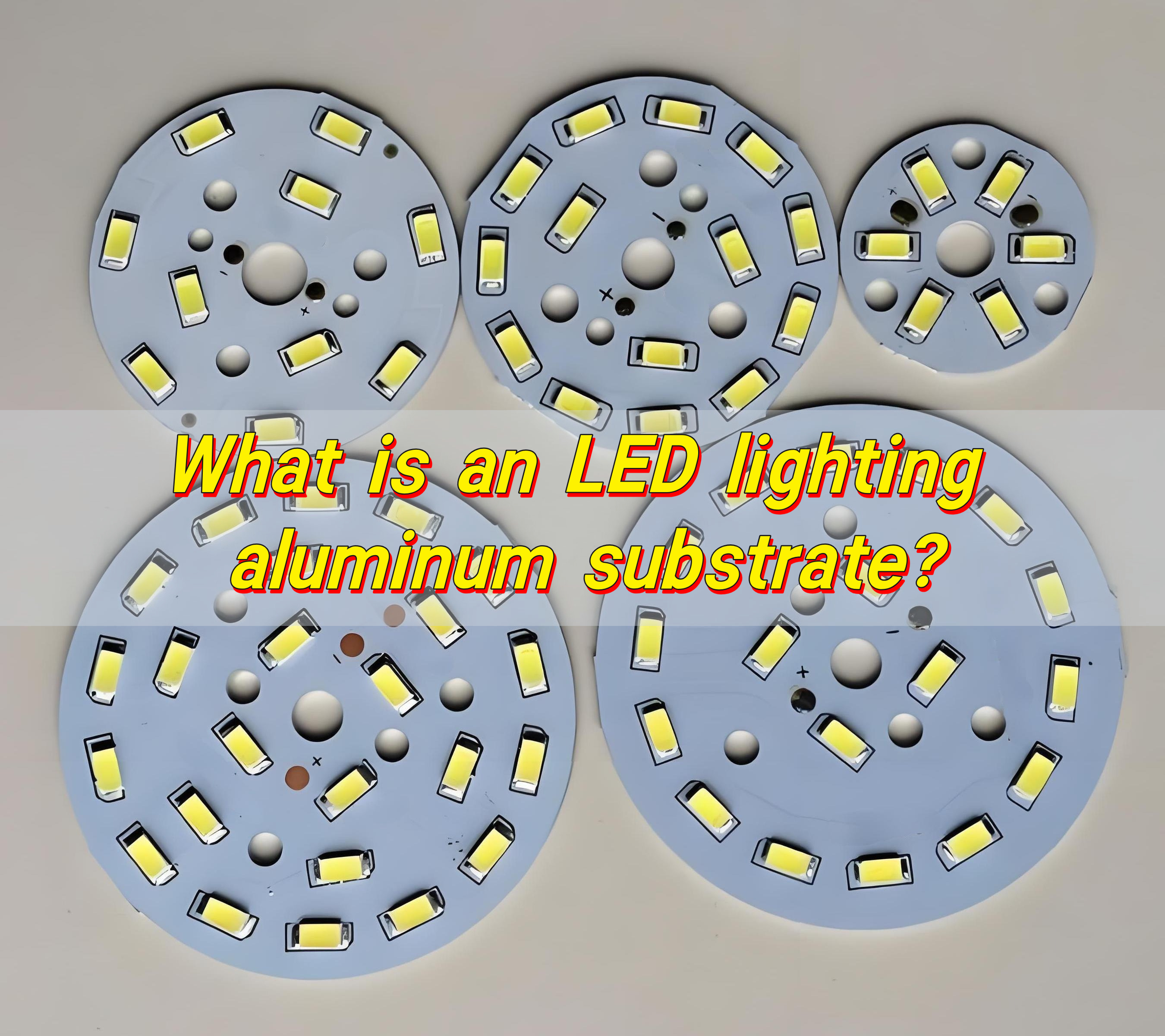
Why Choose 6oz Aluminum PCB for Electronic Control Board?
Reasons why choose 6oz aluminum PCB for electronic control board:
- Heat Dissipation Powerhouse: Thermal conductivity >2.0W/m·K. Reduces component temperatures by 40% vs. FR4.
- High Current Performance: 6oz copper (0.17mm) handles high power loads. Minimizes voltage drop in motor drives/power modules.
- Lightweight & Durable: Aluminum alloy (6063/5052) balances strength and weight. Withstands vibration/industrial environments.
- EMI Shielding: Reduces high-frequency noise in RF/5G circuits. Improves signal integrity with grounding design.
- Cost-Efficient Design: Eliminates heatsinks/fans. Enables compact layouts for space-constrained boards.
- Rugged Reliability: Passes extreme thermal cycling (-40°C~125°C). Surface finishes (ENIG) resist corrosion.
- Scalable Production: Consistent copper thickness for high yields. Customizable layers for diverse control board needs.
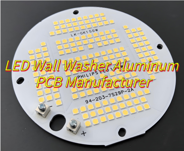
Applications of 6oz Aluminum PCB for EV Electronic Control Board
- Motor Controller (MCU) Power Module
- On-Board Charger (OBC) DC-DC Conversion Circuit
- Battery Management System (BMS) Main Board
- Inverter Power Unit
- PDU (Power Distribution Unit) Busbar
- VCU (Vehicle Control Unit) Power Module
- Thermal-Sensitive Sensor Interface Board
- Fast Charger Power Module
6oz Aluminum PCB for Electronic Control Board Design Specification
| Parameter Category | Specifications/Details |
| Substrate Material | 6063/5052 Aluminum Alloy (High Thermal Conductivity, Corrosion-Resistant) |
| Copper Thickness | 6oz (≈0.17mm, ±10% Tolerance) |
| Thermal Conductivity | ≥2.0W/m·K (Aluminum Substrate Layer) |
| Thermal Resistance | Soldering Temperature: 260°C/10s No Delamination; Thermal Cycling: 3 Cycles (-40°C~125°C) No Cracks |
| Mechanical Properties | Tensile Strength ≥200MPa; Bend Radius ≥1.5×Board Thickness (Non-Plated Side) |
| Surface Finish | ENIG (Au Thickness 0.05~0.1μm), OSP (Antioxidant) |
| Insulation Layer | Epoxy/Polyimide (Thickness 50~150μm, Dielectric Strength ≥500V) |
| Min Trace Width/Space | 0.15mm/0.15mm (Requires Electroplating Process) |
6oz Aluminum PCB for Electronic Control Board Thermal Management
1. Material Selection Criteria
- Base Material: 6oz (170μm) copper-clad aluminum PCB with thermal conductivity ≥3W/m·K.
- Dielectric Layer: Thermal resistance ≤1.2°C·cm²/W, withstand voltage ≥500V.
- Surface Treatment: Anodized finish ≥5μm, surface roughness Ra0.8-1.6μm.
2. Thermal Source Layout
- Maintain ≥30% copper coverage in high-power zones.
- Keep ≥5mm spacing between MOSFET/IGBT components.
- Position temperature-sensitive parts (capacitors) ≥10mm from heat sources.
3. Thermal Path Design
- Thermal via arrays under critical components (0.5mm diameter, 1mm pitch).
- Via filling with thermal conductive paste (≥5W/m·K).
- Direct contact pressure ≥20N/cm² between PCB and housing.
4. Cooling System Configuration
Passive Cooling:
- Fin thickness ≥1.5mm, height ≥20mm.
- Thermal grease thickness 0.1-0.3mm at interface.
Active Cooling:
- Add axial fan when power density >5W/cm²
- Airflow ≥3CFM/W, noise <35dB(A)
5. Process Control
- Soldering: Peak temperature 245±5°C, reflow time ≤90s.
- Assembly: M3 stainless screws (1.2-1.5N·m torque), spring washers ≥0.8mm.
6. Performance Verification
- Thermal resistance (junction-to-ambient) ≤5°C/W.
- Temperature rise ≤45°C under full load.
- Pass 1000 hours 85°C/85% RH aging test.
7. Achieved Results
- 40%+ improvement in heat dissipation efficiency.
- 25-35°C reduction in component operating temperatures.
- System MTBF ≥50,000 hours.
- Compliance with IEC 60068-2-78 damp heat standard.
- 30%+ space reduction compared to traditional designs.

6oz Electronic Control Aluminum PCB Manufacturing Processes
1. Raw Material Preparation
- Procure high-purity electrolytic copper foil (6oz, 210μm thickness).
- Select 5052 or 6061 series aluminum alloy substrate.
- Prepare high-thermal-conductivity insulating dielectric layer (≥8W/mK).
2. Aluminum Substrate Pretreatment
- Mechanically polish substrate surface to surface roughness Ra ≤ 0.2μm.
- Chemically clean to remove surface oxide layers and oil contamination.
- Anodize to enhance surface insulation properties.
3. Insulating Layer Coating
- Apply thermal conductive adhesive uniformly using high-precision coating equipment.
- Curing conditions: 150 ±5℃ for 30 minutes.
- Thickness tolerance controlled within ±10μm.
4. Copper Foil Lamination
- Hot-press composite 6oz copper foil with insulating layer.
- Process parameters: pressure 15–20kg/cm², temperature 180–200℃.
- Ensure no bubbles or delamination defects.
5. Pattern Transfer
- Use LDI (Laser Direct Imaging) technology.
- Special etching compensation design required for 6oz thick copper.
- Minimum line width/spacing: 0.2mm/0.2mm.
6. Etching Process
- Adopt acidic copper chloride etching solution.
- Strictly control side etching rate ≤15%.
- Post-etching copper thickness deviation within ±10%.
7. Drilling
- Use tungsten carbide drills or laser drilling.
- Hole diameter tolerance ±0.05mm.
- Hole wall roughness ≤25μm.
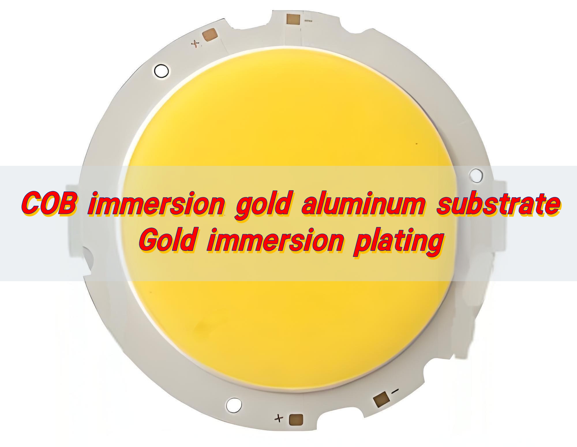
8. Surface Finish
- Optional processes: immersion gold/OSP/HASL.
- Immersion gold thickness: 0.05–0.1μm.
- Nickel layer thickness: 3–5μm.
9. Solder Mask Printing
- Apply high-thermal-conductivity solder mask ink.
- Thickness: 20–30μm.
- Post-curing temperature resistance up to 150℃.
10. Contour Machining
- CNC milling with contour tolerance ±0.1mm.
- V-cut depth controlled at 1/3 of board thickness.
- Chamfering to eliminate burrs.
11. Electrical Testing
- 100% flying probe testing.
- Insulation resistance ≥1000MΩ.
- Withstand voltage test ≥3kV/60s.
12. Final Inspection
- Visual inspection under 10x magnification.
- Full dimensional inspection via CMM.
- Thermal resistance test ≤0.5℃/W.
13. Packaging & Shipping
- Vacuum moisture-proof packaging.
- Anti-scratch spacing between each piece.
- Storage conditions: temperature 15–30℃, humidity ≤60%.
How to Balance Cost and Quality of Electronic Control Aluminum PCB?
1. Material Tiering Optimization
- Critical Zones: Use 6oz copper foil + 6061 aluminum alloy (thermal conductivity ≥200W/m·K) for high-heat components (e.g., IGBTs).
- Non-Critical Zones: Deploy 4oz copper foil + 5052 aluminum alloy, reducing material costs by 15-20% while validating thermal distribution via simulation.
2. Design Standardization & Modularization
- Build a library of universal circuit modules (e.g., power conversion units), cutting custom design time by 30%.
- Use DFM system to auto-check thermal expansion coefficient matching, reducing rework by 67%.
3. Smart Manufacturing Upgrades
- Deploy AI-powered visual inspection to monitor etching uniformity, boosting 6oz thick-copper board yield from 85% to 96%.
- Adopt diamond-coated milling cutters for edge processing, reducing burr rate by 90% and improving soldering reliability.
4. Supply Chain Vertical Integration
- Sign long-term agreements with raw material suppliers to lock copper foil prices; use JIT warehousing to cut inventory costs by 10-15%.
- Prioritize domestic high-thermal-conductivity insulation (e.g., ceramic-filled epoxy), shortening lead times to ≤7 days.
5. Differentiated Surface Finishing
- Apply low-cost OSP (Organic Solderability Preservative) for non-soldering areas and ENIG for critical pads, reducing surface treatment costs by 40% while passing 500hrs 85℃/85%RH tests.
6. Life Cycle Cost Accounting
- Optimize for high-thermal-conductivity insulation (≥8W/m·K): Though 20% more expensive upfront, it reduces cooling components, cutting total life cycle costs by 8-12%.
7. Green Manufacturing & Recycling
- Establish scrap recycling system (70% recycled aluminum utilization), meeting EU 2025 e-waste recycling targets (≥65%).
- Replace traditional stamping with laser cutting, reducing waste rate from 22% to 8% while improving accuracy to ±0.05mm.
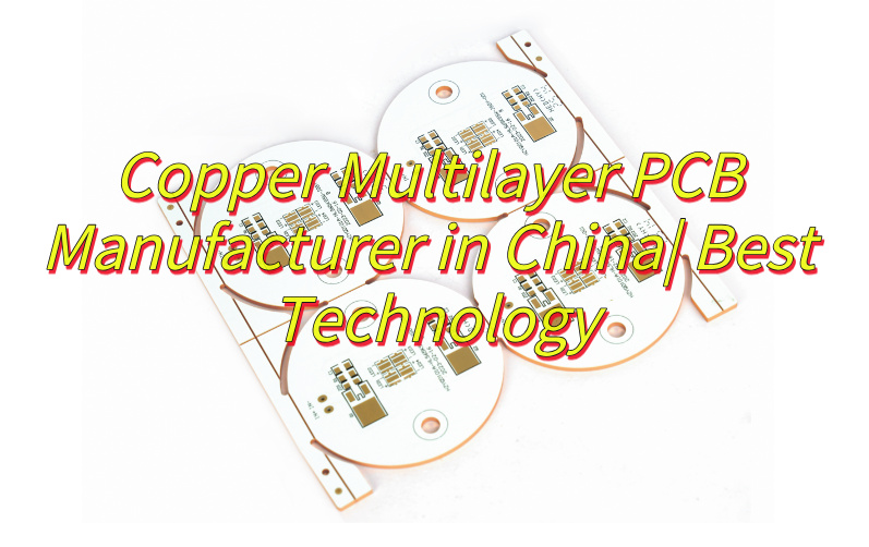
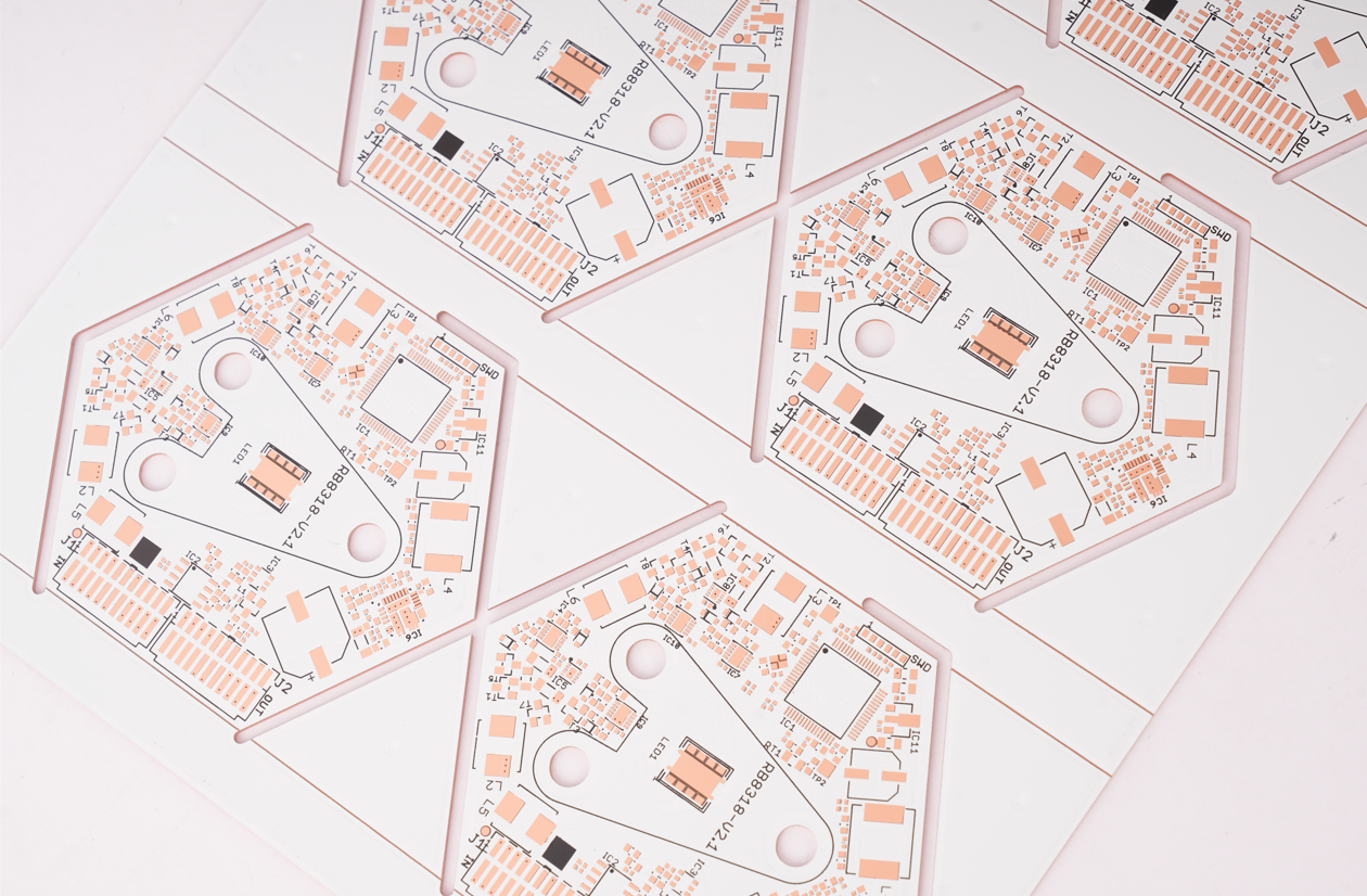
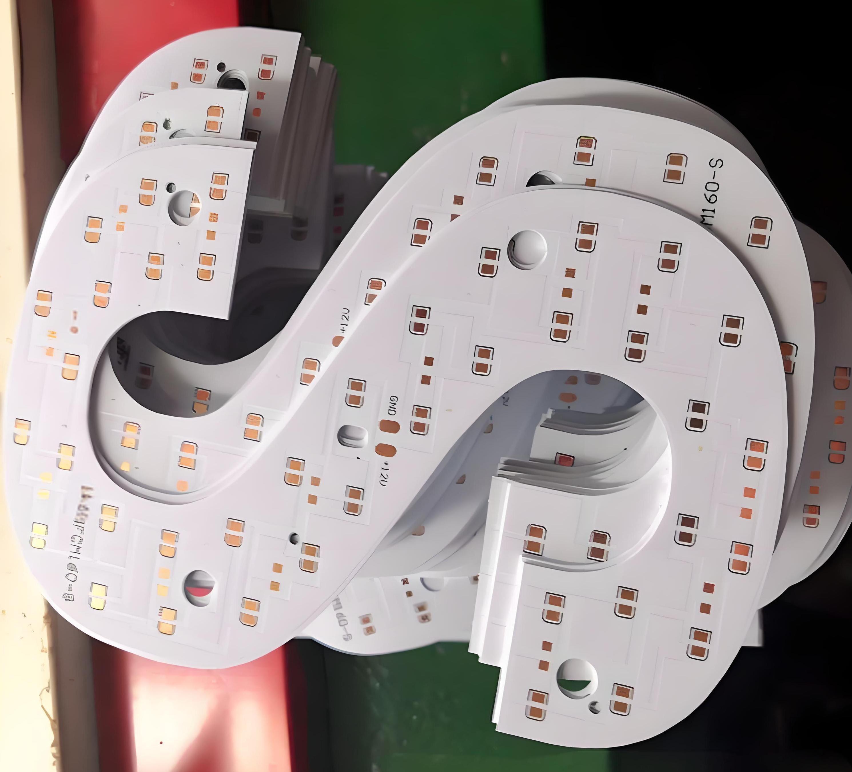
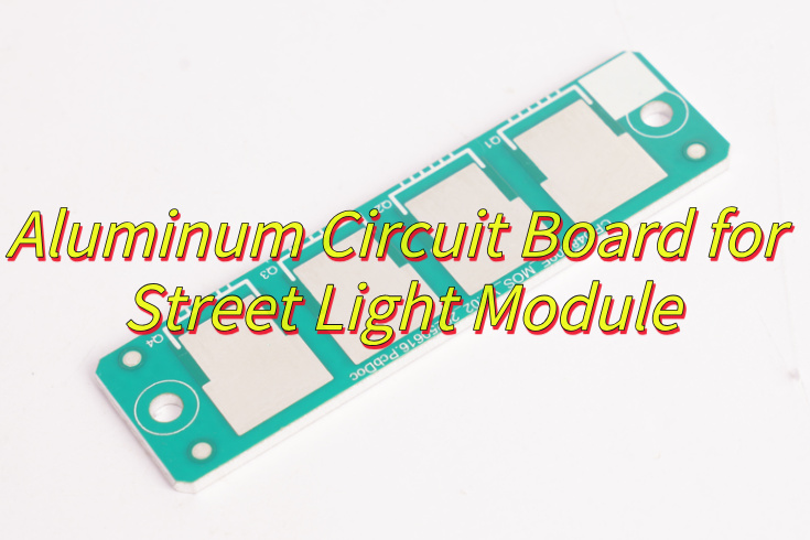
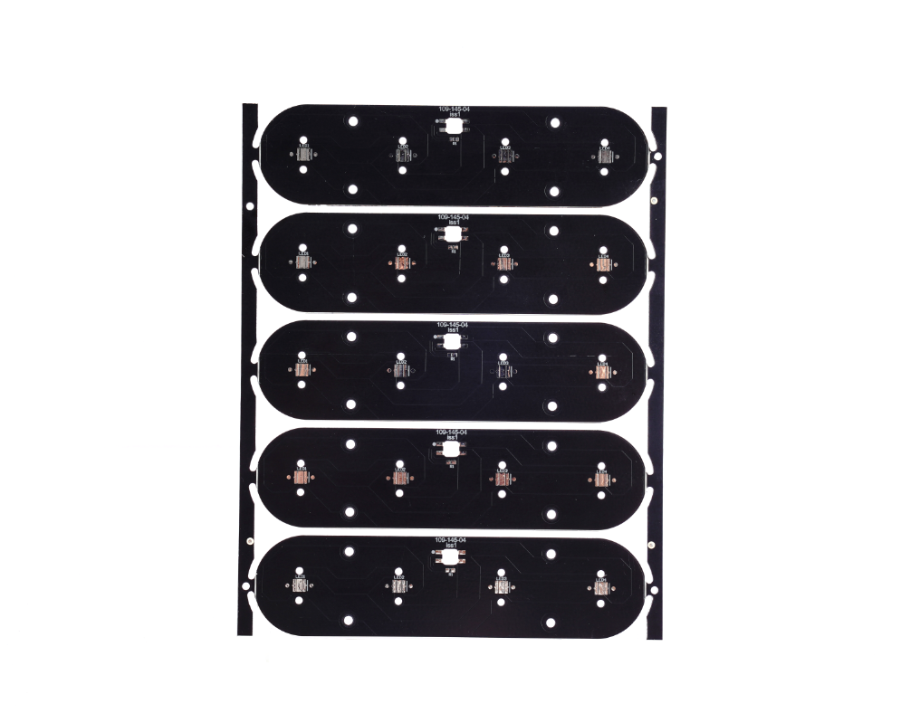
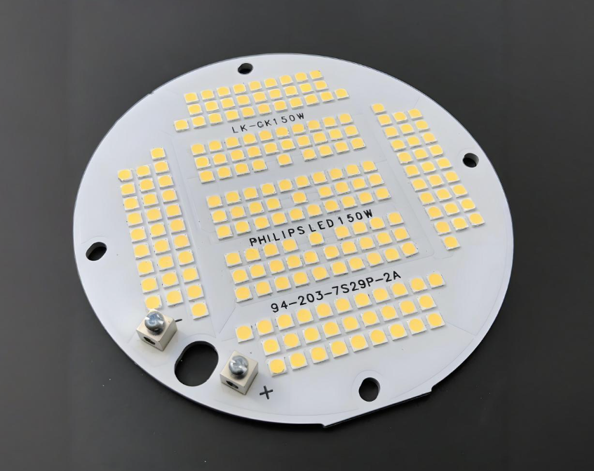
Our Electronic Control Aluminum PCB Case Studies
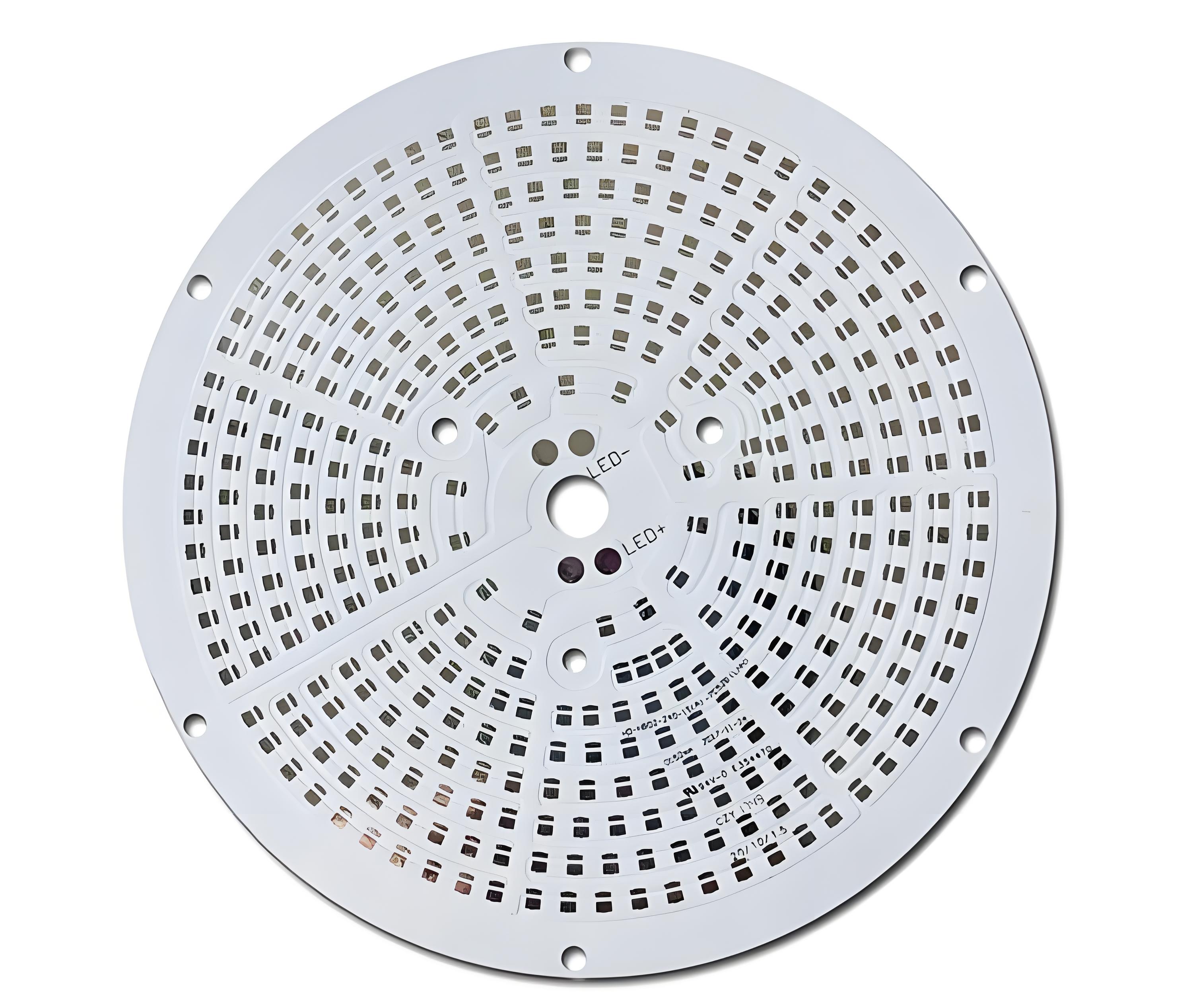
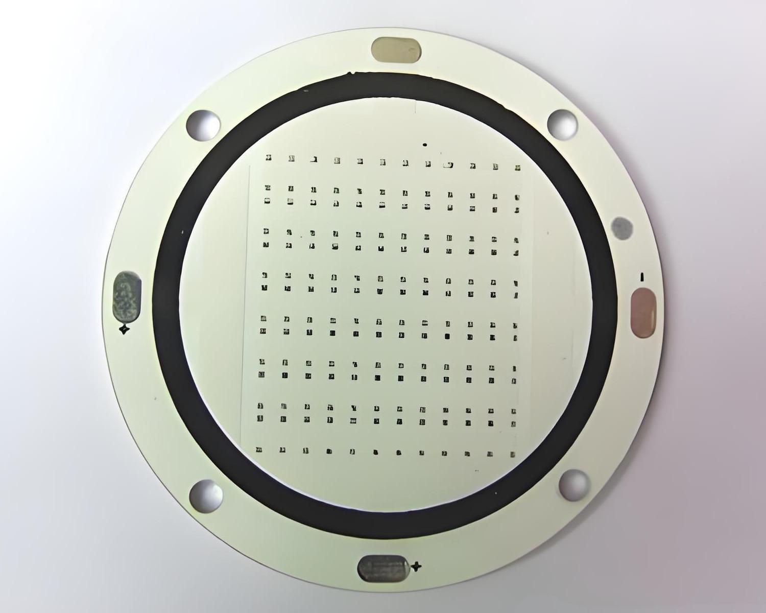
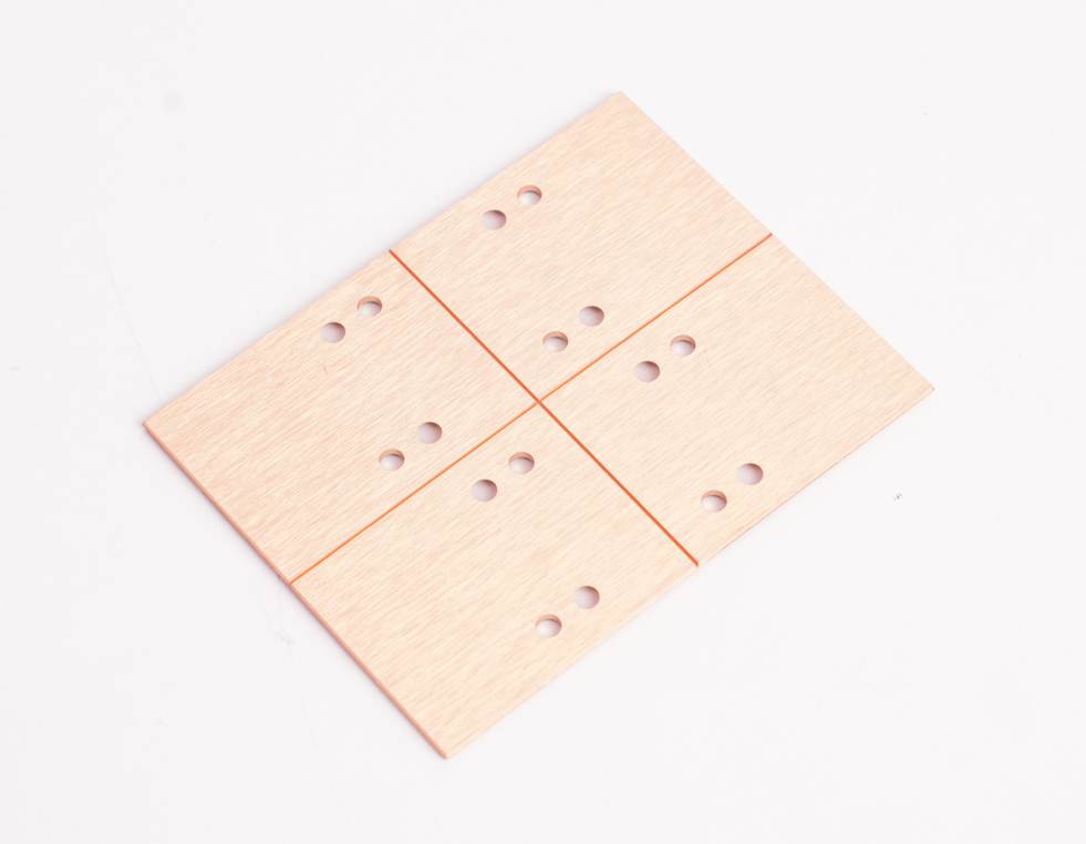
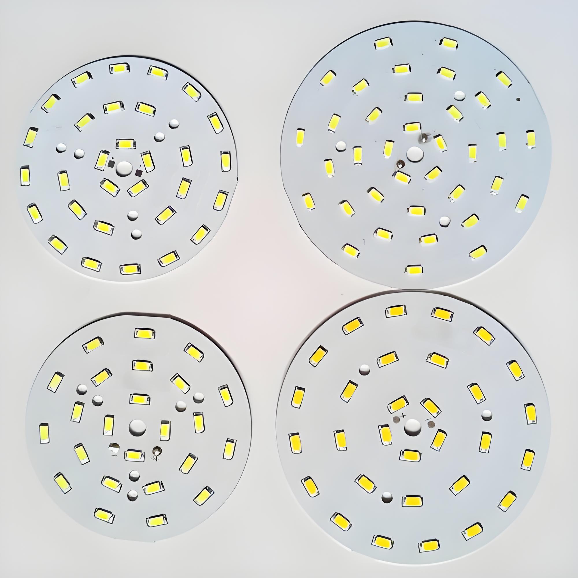
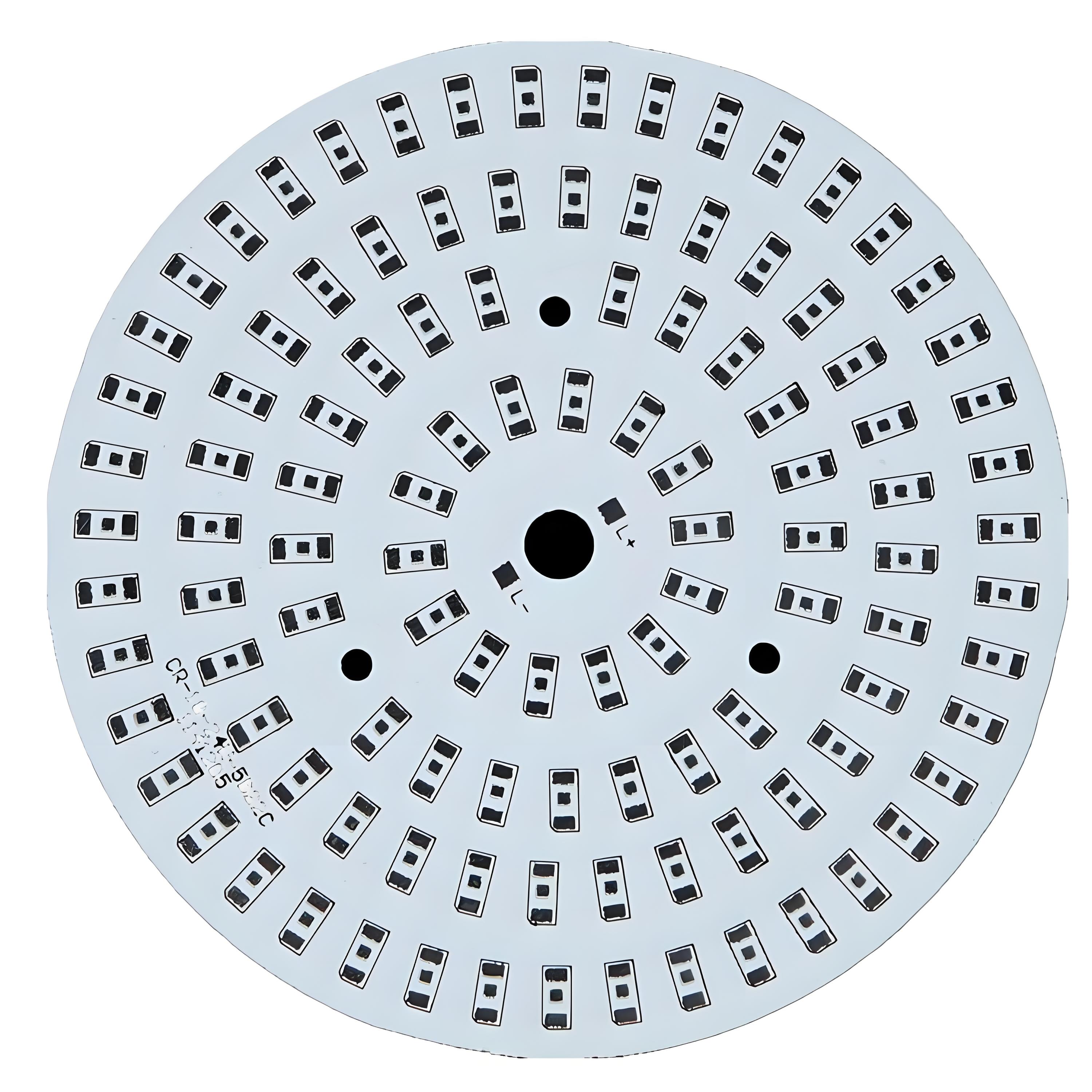
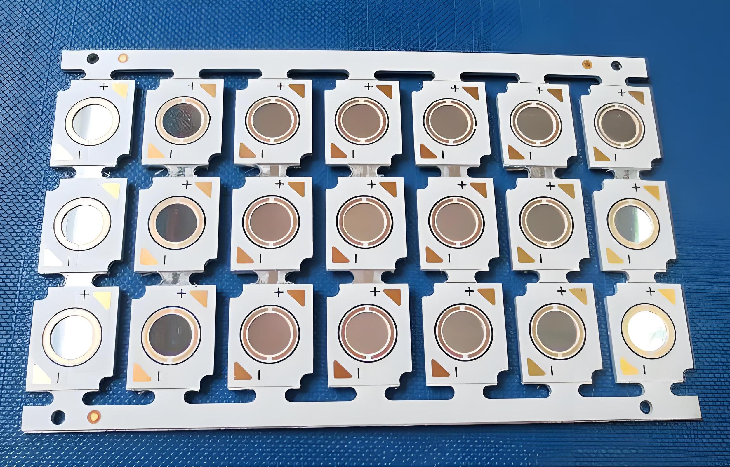
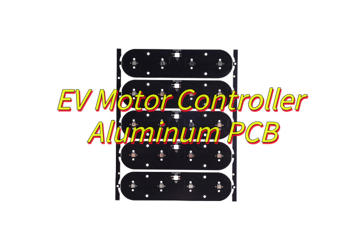
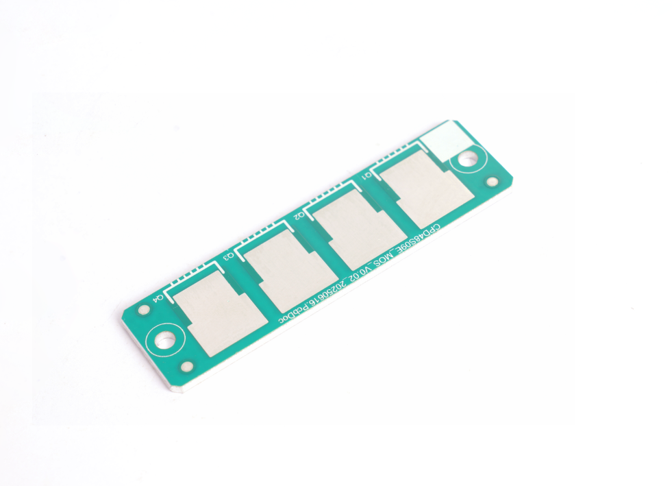
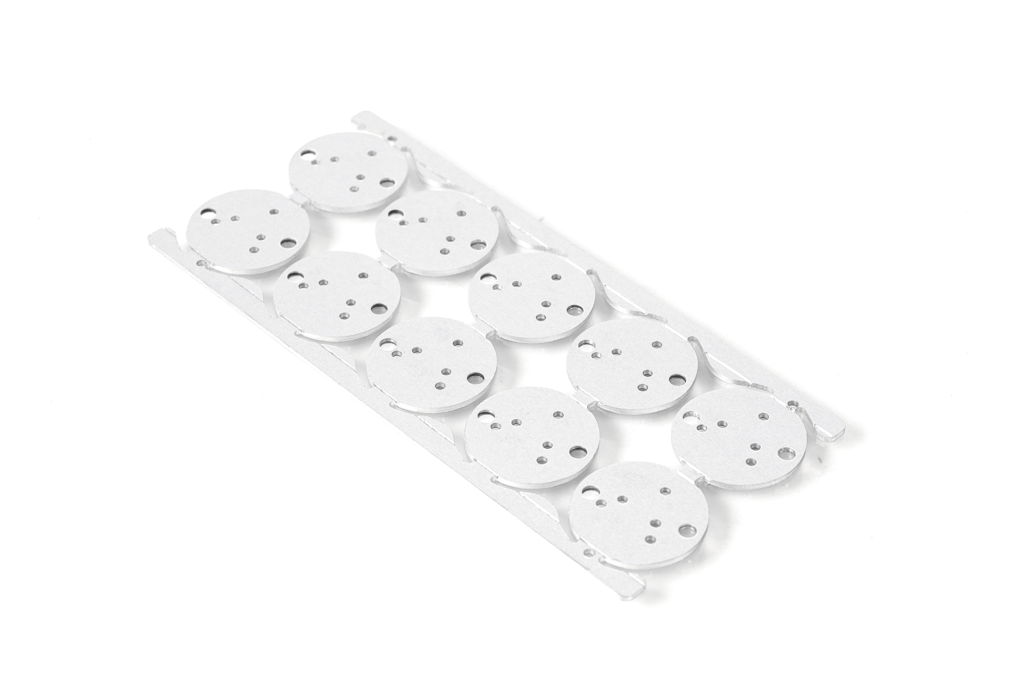
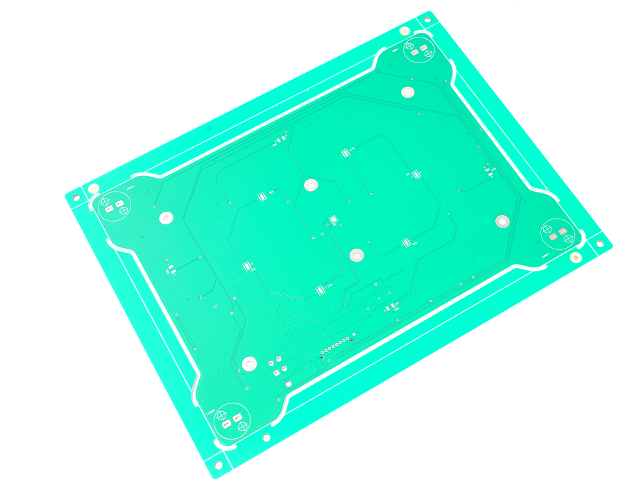
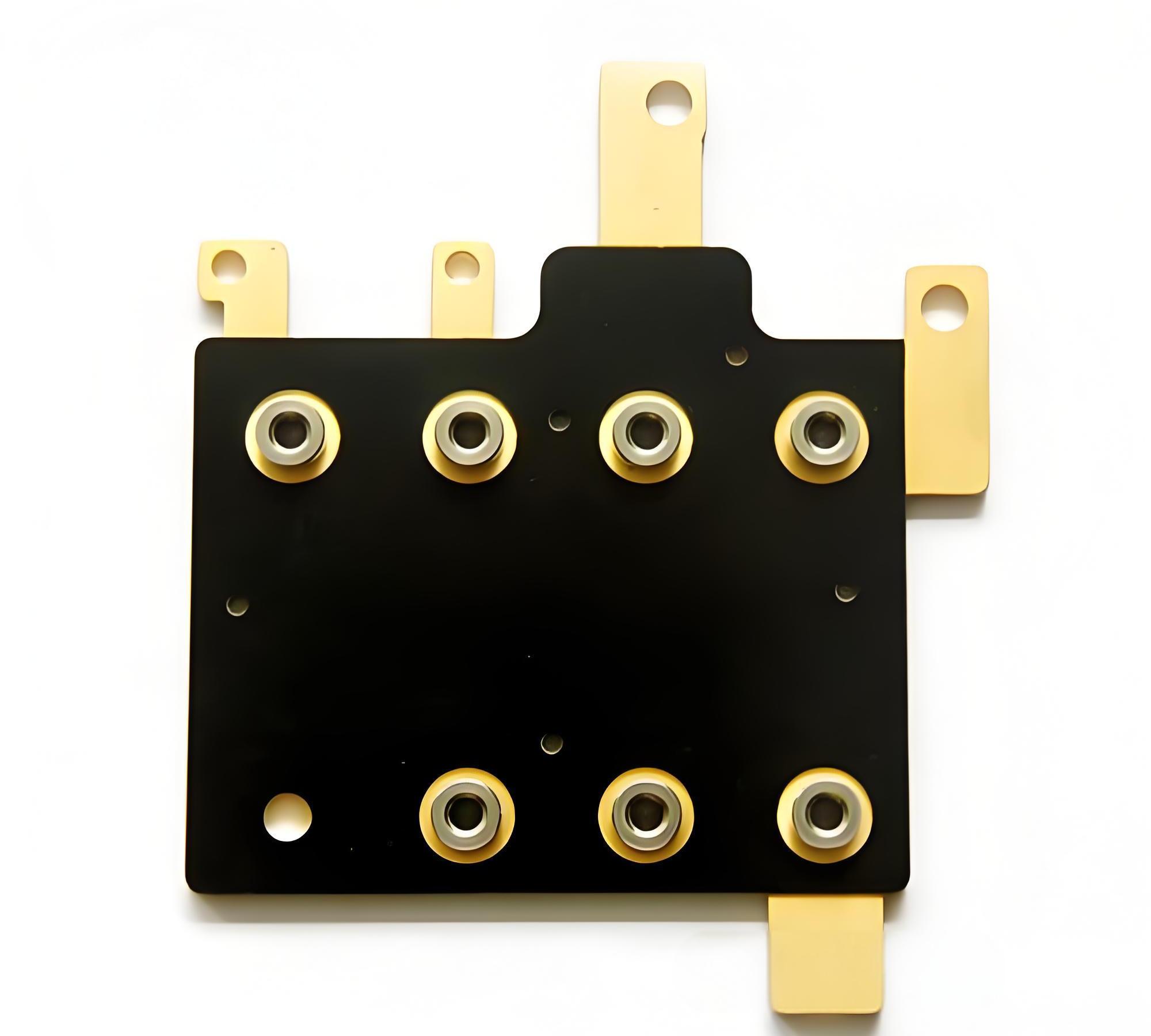
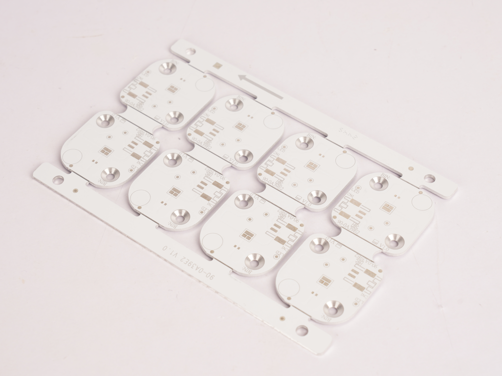
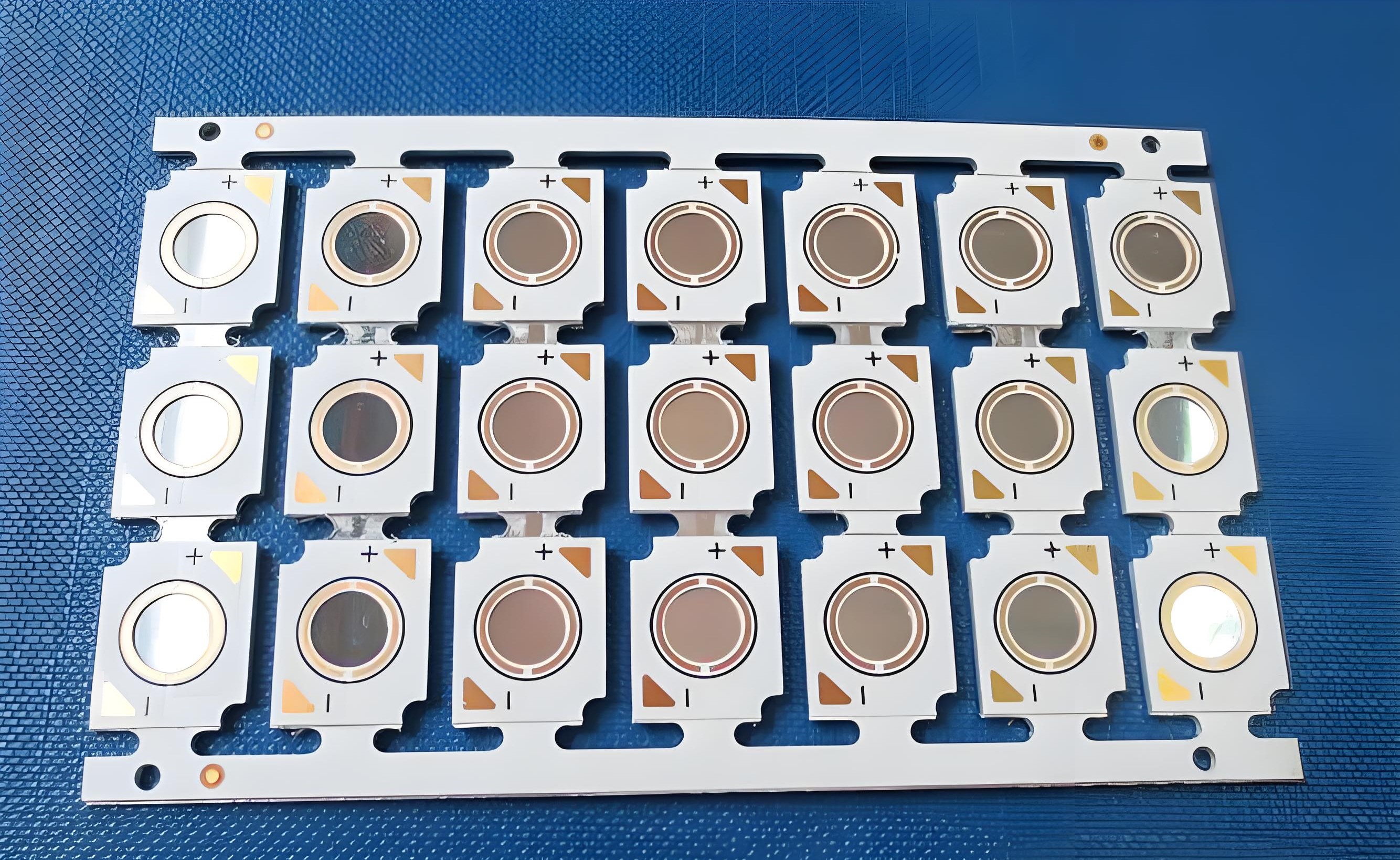
At EBest Circuit (Best Technology), we specialize in electronic control aluminum PCB manufacturing for 19 years, providing a full service from design consultation to mass production. Our professional design team can customize designs based on your power device layout and heat dissipation requirements, ensuring your products meet stringent electrical performance and mechanical stability requirements. Here is a photo of electronic control board aluminum PCB we made before:

Why Choose EBest Circuit (Best Technology) as Aluminum PCB Manufacturer?
Dual-Certification Quality Assurance
- ISO 9001 (general quality) & IATF 16949 (automotive-grade) certified
- Optional medical-grade ISO 13485 compliance
Thermal Management Gradient
- Economy: 3W/m·K aluminum PCB for low-power devices (e.g., security sensors)
- Premium: 8W/m·K aluminum nitride substrate for high-power applications (e.g., 5G base stations)
Supply Chain Efficiency
- Direct sourcing reduces bulk procurement costs by 15%-20%
- Flexible production scale from 50-unit prototypes to 10,000-unit mass production
24-Hour Rapid Prototyping
- Aluminum substrate samples delivered within 24 hours
- Free DFM (Design for Manufacturability) optimization to mitigate thermal via placement risks
Integrated One-Stop Service
- PCB design, thermal simulation, and SMT assembly under one roof
- Engineering support for thermal resistance calculation and temperature rise modeling
Eco-Friendly Manufacturing
- RoHS/REACH compliance with 95% recycled aluminum content
- Lead-free process reduces carbon emissions by 25%
High-Reliability Material System
- Dielectric layer: ≥500V withstand voltage, ≤1.2°C·cm²/W thermal resistance
- Anodized surface (5-8μm thickness), passes 1,000hrs 85℃/85%RH aging test
Precision Fabrication Capability
- Minimum trace width/spacing: 0.1mm
- Laser drilling accuracy: ±0.05mm
- Layer alignment precision: ≤0.03mm
Welcome to contact us if you have any request for aluminum PCB: sales@bestpcbs.com.