How to choose PCB manufacturing companies in USA? This blog is mainly about company list and selection guide to USA PCB manufacturer for your reference.
List of PCB Manufacturing Companies in USA
1. Advanced Circuits (Colorado, USA)
- Main Business: Standard FR4 boards, quick-turn prototypes, low to mid-volume runs.
- Advantages: Strong domestic presence, user-friendly online quote system, stable prototype quality.
- Production Capability: 2–12 layers common, HDI supported in selected runs, 4-mil lines achievable.
- Lead Time: Same-day to 5 days for prototype jobs; longer for complex boards.
2. Sanmina (California, USA)
- Main Business: Complex multilayer boards, rigid-flex, aerospace grade, and full system manufacturing.
- Advantages: Mature supply chain, strong compliance, high reliability for defense and medical use.
- Production Capability: Supports >20 layers, heavy copper, HDI, embedded components.
- Lead Time: 10–25 days depending on complexity and certification needs.
3. TTM Technologies (Multiple States)
- Main Business: High-layer count PCBs, RF/microwave, automotive, military, and aerospace boards.
- Advantages: Very strong engineering base, advanced materials, strict reliability flows.
- Production Capability: 2–60+ layers, advanced RF laminates, high-speed digital stack-ups.
- Lead Time: 10–30 days for most industrial programs.
4. Tempo Automation (California, USA)
- Main Business: Rapid prototype fabrication and assembly for startups and R&D teams.
- Advantages: Fast online quoting, flexible prototype support, strong traceability.
- Production Capability: 2–12 layers, fast-turn PCBA in small lots.
- Lead Time: 48 hours to 7 days for most prototype builds.
5. Benchmark Electronics (Arizona, USA)
- Main Business: High-reliability electronics manufacturing, PCBA, and system-level integration.
- Advantages: Good for industrial, energy, defense, and high-stress environments.
- Production Capability: Multilayer FR4, rigid-flex builds, full assembly lines.
- Lead Time: 15–30 days depending on certification and engineering inputs.
6. Summit Interconnect (California & Colorado)
- Main Business: Complex rigid, rigid-flex, RF/microwave PCBs for advanced applications.
- Advantages: Good customer service, reliable impedance control, tight process management.
- Production Capability: Up to 40+ layers, HDI, stacked microvias, advanced RF laminates.
- Lead Time: 7–20 days depending on layer count.
7. APCT (California, USA)
- Main Business: Multilayer PCBs, HDI, advanced materials like Rogers and Isola.
- Advantages: Rapid-turn capability, friendly engineering consultation, stable yields.
- Production Capability: 2–40 layers, blind/buried vias, hybrid-material builds.
- Lead Time: 5–10 days for FR4; 10–15 days for RF materials.
8. PCB Unlimited (Oregon, USA)
- Main Business: PCB fabrication, stencil service, and small-batch assembly.
- Advantages: One-stop ordering, strong suitability for small businesses.
- Production Capability: 1–12 layers, quick stencil production, prototype PCBA.
- Lead Time: 3–10 days for most builds.
9. Data Tronix (California, USA)
- Main Business: Rigid, flex, and rigid-flex circuit production and assembly.
- Advantages: Good flexibility for project-based orders and custom solutions.
- Production Capability: 2–20+ layers, mixed copper, fine pitch routing.
- Lead Time: 7–14 days for fabrication.
10. EBest Circuit (Best Technology) (China Serving USA Market)
- Main Business: Prototype to mass production for rigid, flex, rigid-flex, HDI, ceramic PCB, and PCBA.
- Advantages: ISO9001, ISO13485, IATF16949, AS9100D certifications; traceability with MES; competitive pricing; free DFM; strong RF, HDI, and ceramic expertise.
- Production Capability: 1–60 layers, heavy copper up to 20oz, HDI 2+N+2/3+N+3, microvias, metal-core boards, ceramic alumina and AlN.
- Lead Time: 24-hour quick-turn prototype; 5–12 days standard; assembly in 7–15 days.
Which Companies Provide PCB Manufacturing and Assembly in the USA?
The USA PCB manufacturer commonly providing both fabrication and assembly include:
- Sanmina
- Benchmark Electronics
- TTM Technologies (selected plants)
- Tempo Automation
- Data Tronix

As a global PCB partner, EBest Circuit (Best Technology) supports USA orders with fabrication, sourcing, assembly, testing, and final inspection in one place.
How to Choose PCB Manufacturing Companies in USA?
A detailed Selection Guide to PCB manufacturing companies in USA:
1. Certification and Compliance Standards
- Core Certifications: ISO 9001 (Quality Management), UL 94 V-0 (Flame Resistance), IPC-A-600 (Visual Standards), ISO 13485 (Medical Devices).
- Environmental Compliance: RoHS 3.0 (EU Regulations), Halogen-Free Certification (Cl+Br<900ppm), REACH-Compliant Materials.
- Case References: Advanced Circuits holds ISO 13485 certification, trusted by leading medical device manufacturers. Cirexx International meets high-frequency RF requirements for 5G applications.
2. Technical Capability Matching
- Quick-Turn Prototyping: Proto Labs offers 24-hour turnaround for R&D prototypes.
- Advanced Technologies: TTM Technologies and Flex Ltd. specialize in HDI, rigid-flex boards, high-frequency RF (5G), and ceramic substrates.
- Material Expertise: Supports Rogers/Taconic high-frequency materials, 20oz copper, and 40-layer board mass production.
3. Quality Control Systems
- Full-Cycle Inspection: Incoming material checks, AOI (Automated Optical Inspection), X-ray inspection for BGA soldering, ICT/FCT functional testing, and environmental stress screening.
- Traceability: Batch tracking linked to process parameters and operator records, exemplified by Sanmina’s medical-grade traceability system.
- Failure Rate Data: Top-tier manufacturers report annual failure rates ≤0.1%, significantly below industry averages.
4. Lead Time Management
- Standard Timelines: Single-layer boards in 3-5 days, double-layer in 4-7 days, 4-layer in 7-10 days, and 8+ layers in 12-15 days. Bulk production can be reduced to 5-8 days.
- Expedited Options: 24/48-hour rush services available for urgent prototyping (additional 30-50% cost).
- Risk Mitigation: Anticipate delays during holidays/peak seasons; confirm capacity upfront and formalize lead time agreements.
5. Customer Support Services
- Design Assistance: DFM (Design for Manufacturability) tools, signal integrity analysis, and blind/buried via optimization.
- Communication Channels: 24/7 multilingual technical support, online quoting systems, and automated Gerber file verification.
- Custom Solutions: Small-batch orders (5+ pieces), PCBA assembly, global shipping with customs assistance, and post-sale technical consultation.
6. Cost-Effectiveness Analysis
- Pricing Benchmarks: U.S. pricing is typically 3-6x higher than Asia but offers superior quality and compliance. Example: 10-layer prototype boards range from $2,500?$4,000.
- Hidden Costs: Rework expenses from defects (often 2-5x order value), supply chain risks from delays, and volume-based tiered pricing.
- Optimization Tactics: Use local quick-turn shops for standard processes; prioritize top-tier manufacturers for advanced needs. Negotiate annual volume agreements for bulk orders.
7. Industry Experience and Case Studies
- Domain Expertise: Medical devices, automotive electronics, 5G communications, and consumer electronics.
- Client Testimonials: Academic teams report “exceeding quality expectations,” while enterprises highlight “consistent service and rapid response.”
- Supply Chain Synergy: Leverage manufacturers with global facilities (e.g., TTM’s sites in Mexico/Singapore) to balance cost and quality control.
8. Sustainability and Logistics
- Eco-Practices: Lead-free soldering, >95% waste recycling, carbon footprint management, and REACH-compliant materials.
- Logistics Solutions: Direct U.S. shipping, anti-static packaging, DHL/FedEx integration, and customs brokerage support.
- ESG Compliance: Environmental declarations and material traceability reports aligned with global ESG standards.

Sticker Shock & Hidden Fees: Clear Pricing Without Extra Bill
Many buyers complain about unexpected charges in the final price. These charges may include mold fees, complex via fees, special material surcharges, or assembly fees. While not all manufacturers hide these items, they still cause concern for US customers.
At EBest Circuit (Best Technology), we insist on price transparency. Quotations list all items upfront, giving engineers and purchasing personnel peace of mind. Furthermore, our quoting team explains various alternatives, such as adjusting the stack-up structure, removing unnecessary impedance pairs, or choosing more manageable surface treatments to reduce costs. This helps US customers develop budgets for PCB projects with greater confidence and avoid extra charges.
Quality Inconsistencies: ISO-Certified Production Process
Some buyers are concerned about issues such as unstable yield rates, pad lifting, impedance misalignment, or plating thickness fluctuations. These issues can disrupt verification programs and impact long-term reliability.
EBest Circuit (Best Technology) holds the following certifications:
- ISO 9001 (General Manufacturing)
- ISO 13485 (Medical Devices)
- IATF 16949 (Automotive Electronics)
- AS9100D (Aerospace Manufacturing)
- UL
- REACH
- RoHS
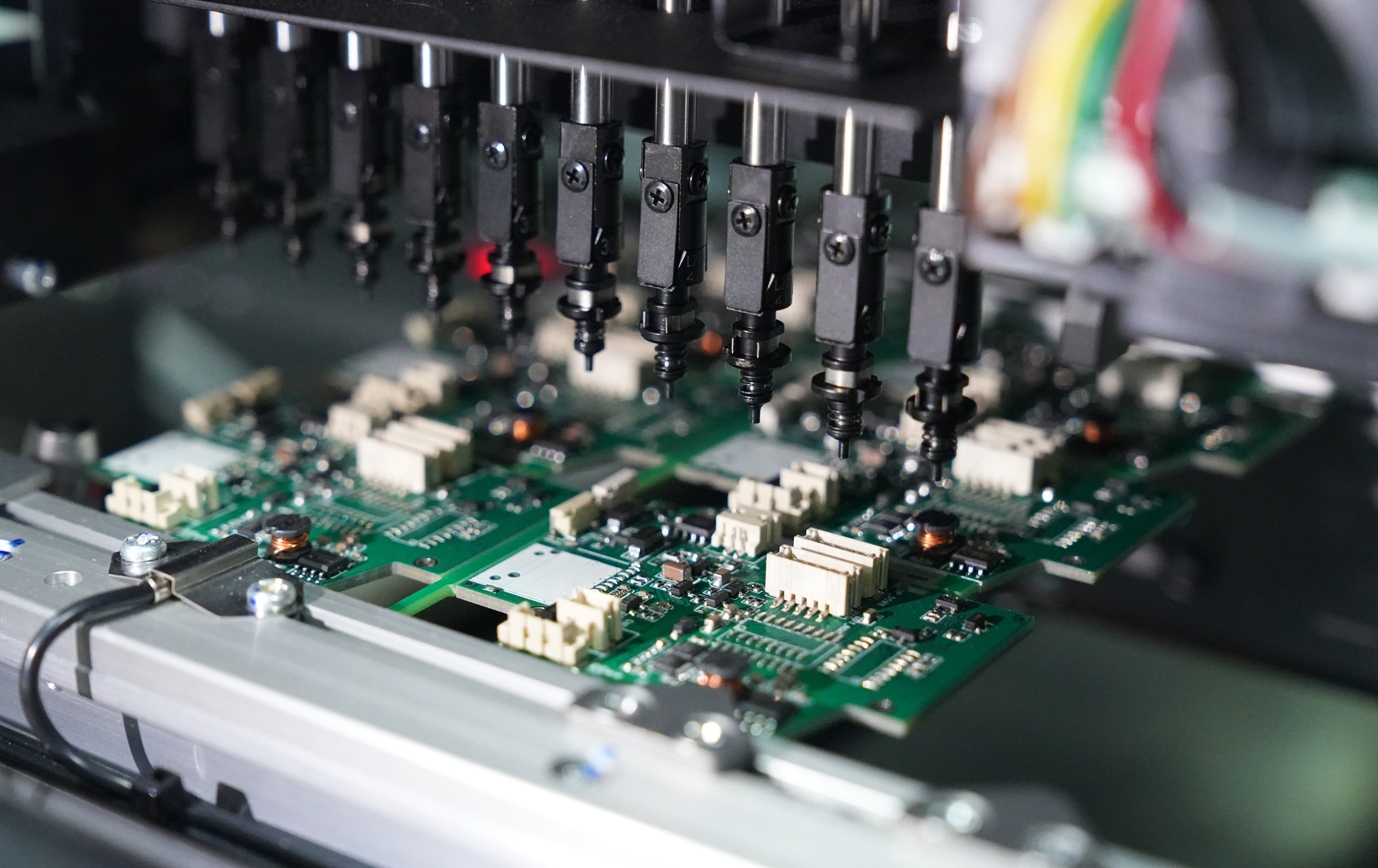
Thanks to these certifications, every order follows a rigorous process from planning to shipment. AOI inspection at each layer, cross-sectional inspection, microvia reliability assessment, and MES traceability ensure consistency for every product. This helps US customers trust the mechanical and electrical stability of our circuit boards from prototype to mass production.
Lead Time Delays: 99.2% On-Time Delivery Rate
Another major concern of clients is long or uncertain lead times. They prefer stable turnaround because many R&D cycles depend on fast validation.
EBest Circuit (Best Technology) maintains a 99.2% on-time delivery rate during the past years. This is supported by:
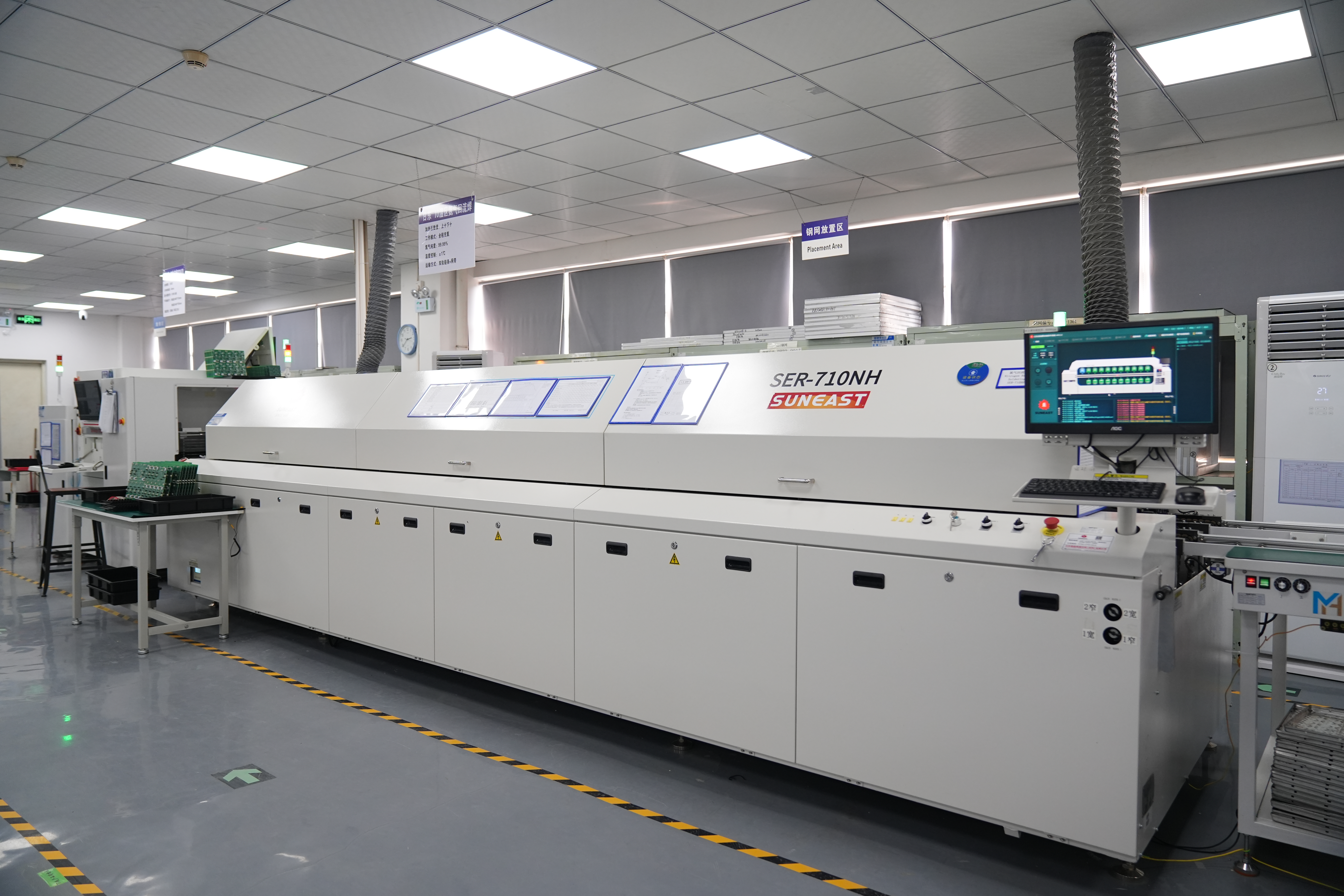
- In-house lamination, drilling, plating, and surface finish lines
- 24-hour prototype lanes
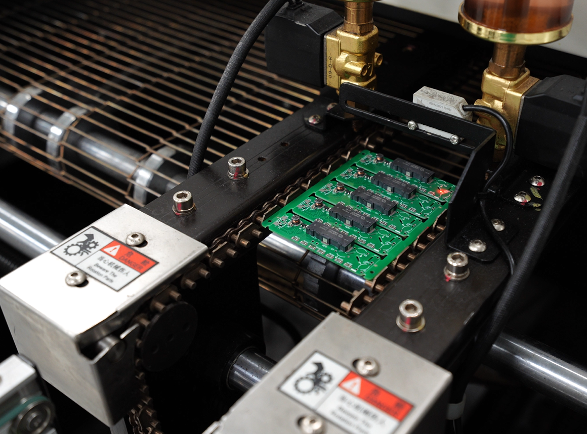
- SMT lines ready for fast assembly
As a result, USA customers enjoy shorter project cycles and fewer interruptions.
No Design Support: Free DFM Reviews & Quick Feedback
Many PCB customers highly value early design support because it reduces layout risk. Some manufacturers simply produce according to the customer-provided documentation, while others point out areas for improvement and help optimize the stack-up structure.
EBest Circuit (Best Technology) offers a free Design for Manufacturability (DFM) review for every order. The engineering team examines impedance, spacing, thermal management, copper balance, drill hole configuration, and manufacturability issues. This helps improve yield and accelerates each round of verification.
Case Studies of Our USA PCB Manufacturing Project
Case Name: Texas AI Hardware Startup H800 Liquid-Cooled AI Server Motherboard R&D Project
Project Background:
- With the explosion of generative AI, demand for high-performance computing hardware in the US has surged. This project, commissioned by a Texas AI hardware startup, aims to develop a liquid-cooled AI server motherboard based on the H800 architecture.
Challenges:
- Design Complexity: Requires support for 800Gbps+ high-speed links, with strict requirements for stack-up and impedance control.
- Yield Pressure: Traditional manufacturing processes result in a 15% scrap rate for microvias, leading to uncontrolled costs.
- Delivery Timeline: Client mandates a 6-week timeline from prototyping to mass production, significantly shorter than the industry standard of 12 weeks.
Technical Specifications
- Layer Count: 16-Layer
- Substrate Material: High-frequency high-speed material (Isola Speed 370HR)
- Process: HDI + Blind/Buried Vias
- Dimensions: 320mm × 260mm (Oversized)
Solutions & Technical Innovations
- Full-Link Simulation: Utilized CST and HFSS for 3D full-wave simulation of stack-up structures prior to panelization. Key optimizations include via inductance effects and dielectric loss reduction, addressing signal attenuation issues.
- AI-Assisted Design (AID): Implemented AI algorithms for automated routing, identifying and avoiding high-risk areas (e.g., power plane splits), reducing design iteration cycles by 40%.
- Stack-Up & Impedance Control: Achieved impedance matching accuracy within ±5Ω for high-speed links through simulation validation.
Project Outcomes:
- Technical Breakthrough: Successfully resolved signal crosstalk issues in 16-layer boards under high-frequency conditions, passing rigorous client functional testing (FTM).
- Yield Improvement: Overall project yield reached 96.2%, a 12% improvement over previous generations.
- Delivery Efficiency: Total project duration reduced by 50%, completing delivery 2 weeks ahead of schedule.
Types of PCB We Can Offer You
- FR4 PCB( Single Layer PCB, 2 Layers PCB, Multi-layer PCB)
- MCPCB(Single Layer MCPCB, 2 Layers MCPCB)
- FPC( Single Sided Flexible Circuits, Double Sided Flexible Circuits, Multilayer Flexible Circuits, Dual Access Flexible Circuits, Rigid-Flex Circuits)
- Ceramic PCB( Thick Film Ceramic PCB, Thin Film Ceramic PCB, DCB Ceramic PCB)
- Heavy Copper PCB
- Bus Bar PCB
- Extra Thin PCB
- High Tg PCB
- HDI PCB
- RF Board

Why USA Clients Choose EBest Circuit (Best Technology) for PCB Manufacturer?
Reasons why USA clients choose us for PCB manufacturer:
- Transparent Pricing with No Hidden Costs: Cost-sensitive pricing system from material procurement to process optimization, no extra fees, free DFM analysis to identify design risks early and reduce over 30% of redesign costs, directly saving clients’ R&D budget.
- 24-Hour Rapid Prototyping for Urgent Orders: Dual-shift production lines and intelligent scheduling system enable 24-hour prototyping for urgent orders, supporting U.S. clients in product iteration or ad-hoc needs and reducing R&D cycle by over 40%.
- 99.2% On-Time Delivery Rate: APS intelligent production scheduling and dynamic supply chain monitoring achieve 99.2% on-time delivery, 15% higher stability than industry average, ensuring zero delays in clients’ production plans.
- 100% Batch Inspection and Strict Quality Control: Triple quality inspection via AOI optical testing, electrical testing and manual review, batch orders undergo 100% full inspection with defect rate below 0.03%, quality consistency verified by ISO 9001 and IATF 16949 dual certifications.
- Multi-Domain International Certifications: ISO 9001, IATF 16949 automotive certification, medical-grade ISO 13485 and RoHS environmental certification meet compliance requirements for U.S. medical, automotive, consumer electronics and other high-threshold industries, reducing clients’ additional compliance verification costs.
- 19 Years of Production Experience and Error Database: 19 years of industry experience with a production error database, optimizing process parameters through historical defect data analysis to lower clients’ repeated error costs and increase first-pass yield to 98.5%.
- Free DFM Design Optimization Service: Free DFM analysis optimizes clients’ designs from a manufacturability perspective, reducing common design errors like laminate defects and pad spacing issues, shortening trial production cycles and lowering mass production risks.
- Turnkey Solutions: Full-process services from PCB design, prototyping to mass assembly, integrating design optimization, material procurement, manufacturing, quality testing and logistics, ensuring seamless linkages across all stages, cutting product launch cycles by over 30% and maintaining quality consistency while reducing cross-departmental communication costs and risks from disjointed processes.
Welcome to contact us if you have any request for PCB design, prototyping, mass production and assembly: sales@bestpcbs.com.