Archive for December, 2020

High-TG FR4 Printed Circuit Board

Thursday, December 31st, 2020

If you work in Printed Circuit Board industry, you may know a normal PCB FR4-Tg is 130-140 degrees, the medium Tg is greater than 150-160 degrees, and High-TG FR4 Printed Circuit Board is greater than 170 degrees.
And what is a High-TG FR4 Printed Circuit Board? High-TG PCB is another name for a high-temperature FR4 PCB, it means the printed wiring boards designed to endure for extremely high-temperature. A Printed Circuit Board is defined as high-TG FR4 PCB if its glass transition temperature (TG) is higher than 170 degrees Celsius. High-TG FR4 will have better mechanical and chemical resistance to heat and moisture than standard FR4. The higher the TG value, the better the temperature resistance of the material, so High-TG FR4 is more and more popular particularly working in high power industry.
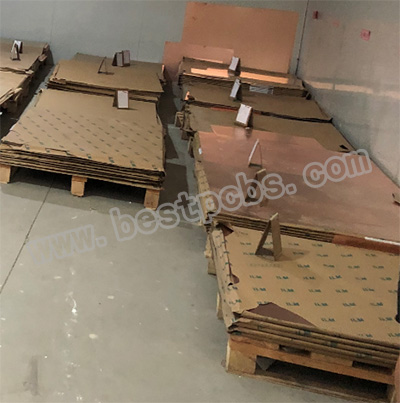
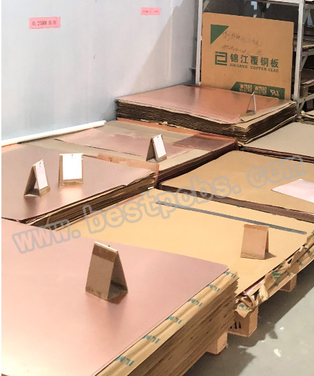
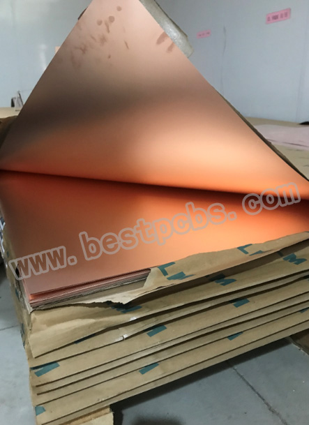
Best Technology can provide many different High-TG FR4 material for Rigid Circuit board, Typical High-TG FR4 PCB material including: ITEQ-IT-180A, ISOLA 370HR, ShengYi S1000-2 and etc.

Part of the inventory of raw material-1
Part of the inventory of raw material-2
Part of the inventory of raw material-3

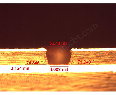
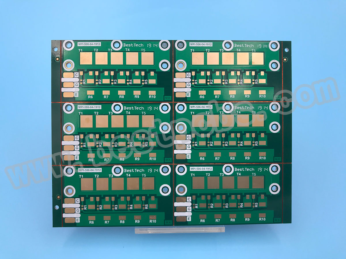
From the following PCB picture, you can see the normal TG130 FR4 PCB substrate is not only softening, deformation, melting, as well as other phenomenon working under high temperatures, but also there is a sharp decline in electrical properties, which will effect on product life.

Solder mask blistering-1
、Solder mask blistering-2

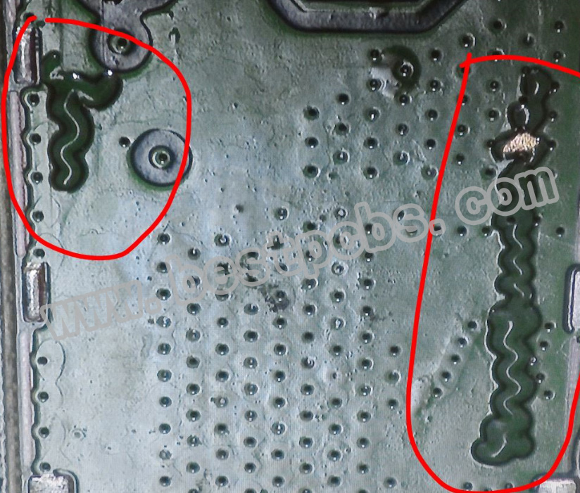
If your FR4 Printed Circuit Board or PCBA board appear to above problems, then you should consider to use a High-TG FR4 Rigid Circuit Board. it may be catching your interest willing to understand a little bit more about High-TG FR4 printed circuit boards. Because High Tg Rigid Circuit board have a better stability at high temperatures, the substrate provides better heat resistance, mechanical and chemical stability for the circuit board.

BPM20396)

Properties/ Applications of high Tg PCB
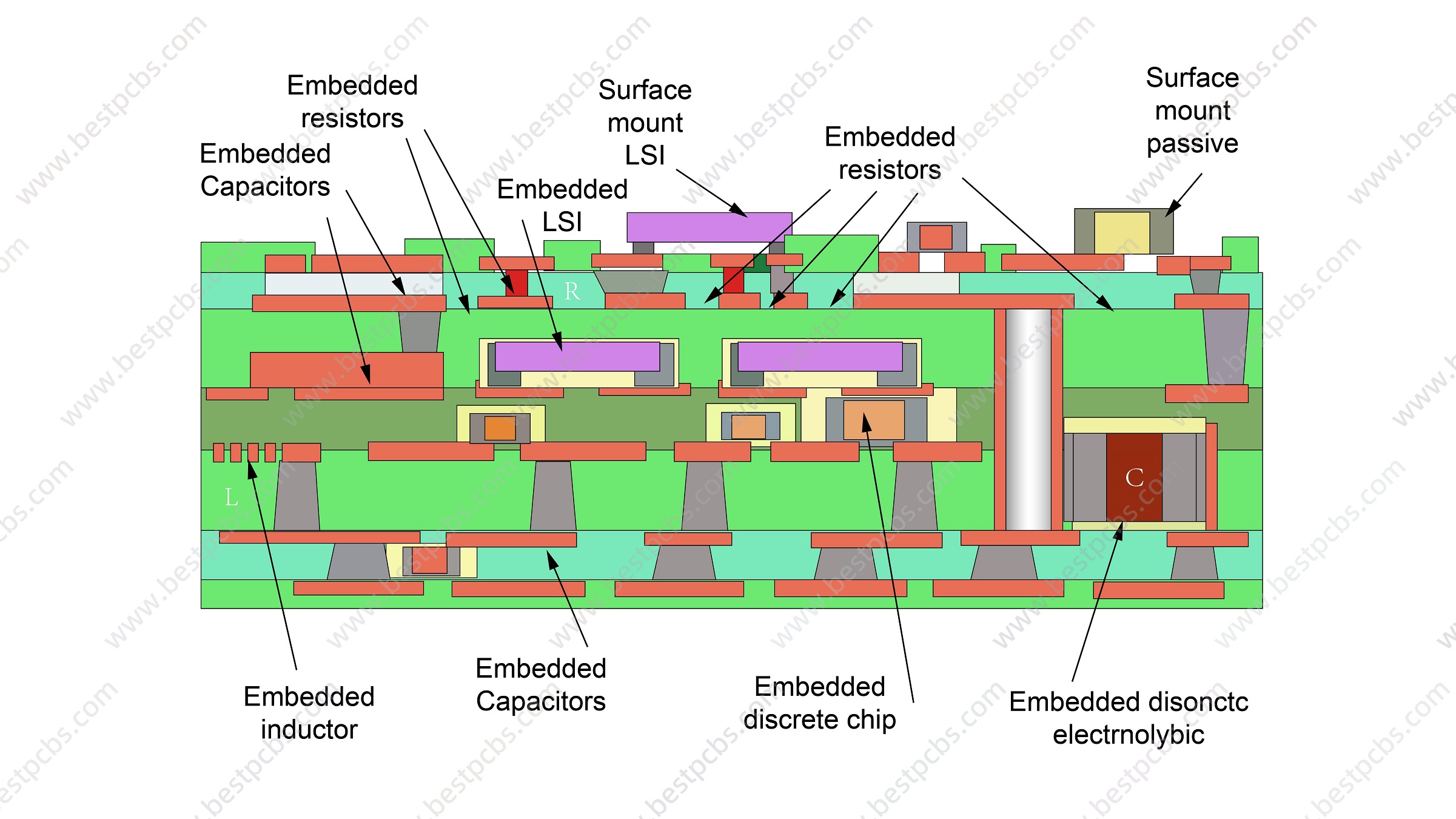
With the rapid development of electronics industry, High-TG FR4 PCB is widely used in Uninterrupted Power Supply, precise instrument as well as industry. High-TG FR4 PCB material probably designed for the high functionality, high multi-layer development high-density circuit; higher heat resistance and high-density surface mounting technology (SMT). So, the demand on High-TG FR4 PCB material become more widely used PCB manufacturing.
What’s more, High TG material is also popular in LED lighting industry, because heat dissipation of LED is higher than normal electronic components, but same structure of FR-4 board is much cheaper than metal core PCB, such as aluminum PCB.
High-TG FR4 PCB materials have the following properties:
 Resistance to high temperatures
 Long delamination durability (aging of materials to consider for safety reasons)
 Low thermal expansion
Excellent PTH reliability
Good mechanical properties
High temperature durability
High value of thermal stress resistance
high temperature durability
long delamination durability
Low Z axis expansion (CTE)

BPM19308

Advantages of High-TG FR4 PCB
Higher stability: it will automatically improve the heat resistance, chemical resistance, moisture resistance, as well as stability of the device if increasing the TG of a printed circuit board substrate.
Bear high power density designs: high TG PCB will be a good solution for heat management if the device has high power density with quite high heat generation rate.
It can achieve with using a larger printed circuit board to change the design and power requirements of a device when reducing the heat generation of ordinary board, what’s more, it also can use the high TG PCB.
Ideal for multilayer & HDI PCBs: there will lead to high levels of heat dissipation because multilayer & HDI PCBs are more compact and have dense circuits. So high TG PCBs are often used for the multilayer & HDI PCBs so that it can make sure reliability in Printed circuit board fabrication.

BPM20005 TOP
BPM20005 BOT

 If your applications are in any danger of subjecting your PCBs to extreme temperatures or the PCB is required to be RoHS Compliant, it will be in your best interest to look into high-TG FR4 PCBs.
Come to contact Best Technology Co., Limited. for High-TG PCB assistance. we can help you determine if you need high-temperature printed circuit boards and direct you to which specific boards are likely to be useful for your design and application. If you are transitioning to RoHS or just need more information about the High TG laminates, just give us a call and we’ll be happy to accommodate you. contact us online right now.

You may also like

What’s RT/duriod 5880?

Tuesday, December 1st, 2020

For PCB materials, you may have ever heard about many different kinds of materials such as the materials of FR4, Aluminum, Copper base and ceramic base.

But do you know what the duriod 5880 materials is?

Actually duriod 5880 is a kind of materials of the Rogers, it is the materials which is used for high frequency circuit board. RT 5880, which is famous for its low dielectric loss, low moisture absorption, and stable dielectric constant. The PCB made of duriod 5880 can be widely used in airborne and ground-based radar systems, millimeter wave applications, and space satellite transceivers.
Different with other kinds materials, the color of the RT 5880 materials is black.

Why this material can be used in such high end field? Let’s see below to know more information.

Excellent dielectric properties:
RT/duroid 5870/5880, as a new generation of high-frequency laminate, is made of polytetrafluoroethylene composite material (PTFE). At the same time, glass microfibers are randomly distributed in the material, which provides the greatest strength during the production and application of the circuit board.

High-frequency circuit design has strict requirements on the dielectric constant of the printed circuit board. RT/duroid 5880 has an ultra-low dielectric constant and remains the same in a very wide operating frequency range.

At 10GHz operating frequency, the measured dielectric constant is only 2.33/2.2, which is significantly lower than similar materials on the market. Therefore, from the perspective of performance parameters and production costs, the board is more suitable for high-frequency application design than similar products.

At the same time, under the same standard (f=10GHz), and the dielectric loss of the RT5880 is only 0.0012/0.0009. The extremely low dielectric loss makes it very suitable for high-frequency and the field of wide-band applications which requiring minimal dispersion and low loss.

In addition, the extremely low moisture absorption rate makes it an ideal choice for applications in high humidity environments. The moisture absorption rate of RT/duroid 5880 is only 0.02%, so it can meet the strict requirements of mechanical reliability and electrical stability in the complex microwave structure design, and it is also suitable for applications in high humidity environments.

With the continuous improvement of the operating frequency of high-frequency circuits, the requirements for the dielectric constant and dielectric loss of the circuit board are becoming more and more stringent. The excellent performance of RT/duroid 5880 in these two aspects can significantly improve the design of high-frequency circuits. Definity, improve circuit performance.

Easy to process and install
In this high-frequency design, in order to meet the requirements of electromagnetic shielding and compact design, printed circuit boards are often installed in various irregularly shaped cavity structures. Therefore, the PCB board must be designed in different shapes and suitable for production and Installation.

For RT/duroid 5880 laminate, which is easy to cut, trim and good for PCB manufacturing.

At the same time, it can resist all the solutions and chemical agents used in the process of etching and plating through holes, and it has a good performance of the cold and heat resistance.

The composite material RT/duroid 5880 can be covered with a laminated copper foil for some key electrical applications, and brass plates or copper can also be used as required.
Usually laminates of the RT/Duriod 5880, it can make double-sided copper clad with thicknesses ranging from 1/2 oz. to 2 oz./ft2 (8.5~70 μm) to meet most custome’s requirements for the thickness of copper foil.

Our company has focus on the PCB fabricationi for more than 15 years, we can make PCB with Rogers PCB with RT/Duriod 5880, as well as RO4003C and RO4350B with different thickness.
If you are interesting to know more and your PCB also want to made of RT/Duriod 5880, please feel freely to contact us for more information related.

You may also like

The main factor affect the heat dissipation of Metal Core PCB

Tuesday, December 1st, 2020

various LED applications due to its good heat dissipation, do you know what factors can affect the heat dissipation?
As we all known, MCPCB(Aluminum/Copper/Stainless steel) is widely used in
One of the reasons is that Metal base board use special substrate material which is specifically formulated to improve the reliability of designs that run at higher than normal temperatures. Instead of serving strictly as a mounting surface for the various components, the substrate actively draws heat from the locations of hot-running components through to the opposite layer of the board where it can dissipate efficiently and safely, it’s the Dielectric Layer, which is the main factor affect the heat dissipation.

Some people may also mistakenly believe that the dielectric layer is thicker, the heat dissipation will be better. Actually the thickness of Dielectric Layer depends on the customer’s design requirements, it will not effect on heat dissipation. What affects heat dissipation is the material of the dielectric layer, also known as thermal conductivity.

Compare to Metal base board, FR4 PCB has low thermal conductivity, typically around 0.3W, while MCPCB has higher thermal conductivity, which include 1.0W, 2.0W, 3.0W, 7.0W, 8.0W.

In order to save the cost, not all boards need to use 3W dielectric layer. 1W is enough for 2835 or 3030 LED. High power LED like Cree need to use 3W.

If you have other questions about MCPCB, welcome to contact Tammy (Email:sales@bestpcbs.com), she will prove you professional suggestions and solutions.

You may also like