

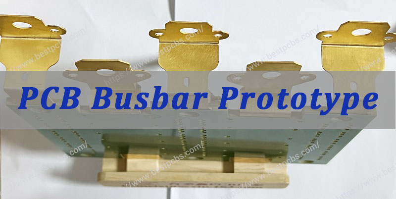
PCB busbar prototype plays a critical role during early product development. It allows engineers to validate electrical performance, thermal behavior, and mechanical integration before moving into full production. For power systems such as inverters, motor drives, EV chargers, and industrial power supplies, this prototyping stage significantly reduces design risk.
If you are developing a high-current power board and require custom PCB busbar prototype fabrication, working with an experienced engineering team is essential. At EBest Circuit (Best Technology), we support engineers with DFM analysis, busbar integration guidance, PCB fabrication, component sourcing, and PCBA assembly. Our vertically integrated facilities help reduce development cycles while ensuring stable electrical performance. For project consultation or quotation, feel free to contact us at sales@bestpcbs.com.
What Is a PCB Busbar Prototype?
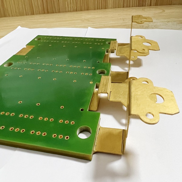
A PCB busbar prototype is a preliminary version of a high-current circuit board that integrates solid copper busbars with traditional PCB structures. Instead of relying solely on copper traces, the design introduces thick copper conductors capable of handling significantly larger current loads.
Busbars typically consist of:
- Solid copper bars
- Copper plates
- Formed laminated conductors
These conductors are mounted or embedded into the PCB to create low-resistance current paths.
Key functions of a PCB busbar include:
- Reducing resistive losses
- Improving current distribution
- Lowering thermal buildup
- Supporting high-power devices
Compared with conventional copper traces, busbars provide much larger cross-sectional area, enabling significantly higher current capacity without excessive temperature rise.
During the prototype phase, engineers validate several critical factors:
- Electrical conductivity
- Thermal performance
- Mechanical mounting
- Insulation spacing
- Assembly compatibility
This validation step ensures the design performs reliably before entering volume manufacturing.
Why Do High Current PCB Designs Use Busbars?
In high-power electronic systems, copper traces alone may struggle to handle large current loads. Even with thick copper layers such as 4 oz, 6 oz, or 10 oz, the trace width required to carry hundreds of amperes becomes impractical.
Busbars solve this problem.
Key advantages of busbars in PCB designs
1. Higher current carrying capacity
Busbars provide significantly larger conductor cross-sections, allowing them to carry currents exceeding 100A or even several hundred amperes.
2. Lower electrical resistance
Solid copper conductors reduce voltage drop, improving overall system efficiency.
3. Better thermal management
Busbars dissipate heat more effectively, helping prevent localized hotspots on the PCB.
4. Improved power distribution
Power electronics systems require stable current distribution. Busbars ensure uniform current flow across multiple components.
5. Mechanical robustness
Busbars provide stronger mechanical connections compared with thin copper traces.
Because of these advantages, many power electronics engineers rely on busbar-based PCB designs when building high-current systems.
Busbar PCB vs Heavy Copper PCB
Engineers often debate whether to use busbars or heavy copper PCBs. Both solutions address high current requirements but differ in capability.
| Feature | Busbar PCB | Heavy Copper PCB |
|---|---|---|
| Copper thickness | External copper bar | Thick copper layers |
| Current capacity | Extremely high | Moderate to high |
| Heat dissipation | Excellent | Moderate |
| Design flexibility | Medium | High |
| Manufacturing complexity | Higher | Moderate |
| Cost | Higher for prototypes | Lower |
When to use heavy copper PCBs
Heavy copper PCBs are suitable when:
- Current levels are below 100A
- Trace widths remain manageable
- Thermal loads are moderate
When to use busbars
Busbars are preferable when:
- Current exceeds 100A
- Space constraints limit trace width
- High power distribution is required
- Thermal management becomes critical
Many modern power electronics designs combine both technologies, using heavy copper layers alongside integrated busbars.
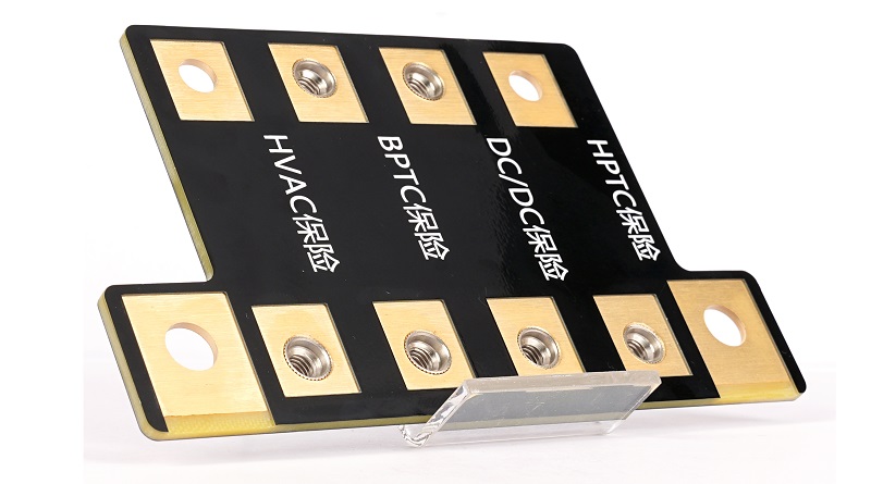
Applications of PCB Busbar in Power Electronics
PCB busbars appear in a wide range of high-power electronic systems.
Industrial motor drives
Motor control systems often require large currents to drive high-power motors. Busbars distribute current between power modules, capacitors, and drivers.
Electric vehicle power systems
EV electronics rely heavily on high-current PCBs. Busbars are commonly used in:
- On-board chargers
- Battery management systems
- DC-DC converters
- Traction inverters
Solar inverters
Solar power systems convert DC energy into AC power. Busbars provide efficient current flow between power semiconductors.
Industrial power supplies
High-capacity switching power supplies require stable power distribution across multiple components.
Energy storage systems
Battery storage platforms use busbars to connect high-current power modules safely and efficiently.
How to Design a Busbar PCB for High Current Applications?
Designing a busbar PCB requires careful planning to ensure electrical safety and thermal stability.
Determine current requirements
Engineers must first define:
- Maximum current load
- Continuous vs peak current
- Safety margins
These parameters determine busbar thickness and width.
Optimize current paths
Current flow should follow the shortest possible path to minimize resistance.
Maintain proper spacing
High current systems often involve high voltage. Adequate spacing between conductors is essential for safety.
Integrate mechanical support
Busbars require mechanical mounting to ensure structural stability during operation.
Consider assembly methods
Busbars may be attached using:
- Bolted connections
- Press-fit terminals
- Soldering
- Ultrasonic welding
Proper assembly design ensures reliable electrical contact.
Materials Used in PCB Busbar Manufacturing
Busbars typically use high-conductivity copper materials.
Common materials include:
Electrolytic tough pitch copper (ETP)
This copper grade offers excellent electrical conductivity and is widely used in power applications.
Oxygen-free copper (OFHC)
OFHC copper provides improved conductivity and better resistance to oxidation.
Tin-plated copper
Tin plating helps protect copper from corrosion and improves solderability.
Nickel-plated copper
Nickel plating improves mechanical durability and oxidation resistance.
Silver plating
Silver coating provides excellent conductivity and low contact resistance.
Material selection depends on:
- Current capacity
- Environmental conditions
- Mechanical requirements
- Cost considerations
How to Calculate Current Capacity of PCB Busbars?
Determining the current carrying capacity of a busbar requires evaluating several factors.
Key parameters
- Cross-sectional area of the conductor
- Copper conductivity
- Ambient temperature
- Cooling conditions
- Maximum allowable temperature rise
A simplified approach is:
Current Capacity ∝ Cross-Sectional Area
For example, a thicker busbar with greater cross-sectional area can carry more current without excessive heating.
However, accurate calculations typically require thermal simulation and empirical testing during the prototype stage.
PCB Busbar Thermal Management Considerations
Thermal management is crucial in high-current PCB designs.
Excess heat can cause:
- Component failure
- Solder joint degradation
- Reduced system lifespan
Effective thermal strategies
1. Increase conductor thickness
Thicker busbars reduce electrical resistance.
2. Improve airflow
Forced airflow helps dissipate heat generated by high currents.
3. Use thermal vias
Thermal vias help transfer heat away from hot components.
4. Add heat sinks
Heat sinks provide additional cooling for high-power devices.
5. Optimize layout
Distributing heat sources evenly across the PCB reduces localized hotspots.
Thermal simulation during the prototype stage helps engineers optimize these design factors.
How to Manufacture a PCB Busbar Prototype?
Manufacturing a PCB busbar prototype involves several specialized processes.
PCB fabrication
The base PCB is fabricated using standard multilayer PCB manufacturing processes.
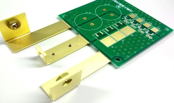
Busbar fabrication
Copper bars are cut, formed, and plated according to the design.
Surface finishing
Common finishes include:
- Tin plating
- Nickel plating
- Silver plating
Mechanical assembly
Busbars are attached to the PCB using mechanical fasteners or soldering.
Electrical testing
Prototype boards undergo electrical testing to verify current flow and connectivity.
Thermal validation
Thermal testing confirms the design can safely handle expected current loads.
Working with an experienced manufacturer ensures accurate fabrication and reliable prototype performance.
Common Challenges in Busbar PCB Design
Although busbar PCBs offer many benefits, they also introduce several engineering challenges.
Mechanical integration
Busbars require proper mounting and support to prevent mechanical stress.
Thermal expansion
Copper expands when heated, which can affect connections over time.
Assembly complexity
Busbar assembly often requires specialized processes.
Electrical insulation
High-current systems must maintain adequate insulation spacing.
Cost considerations
Busbar prototypes may cost more than conventional PCBs due to additional materials and processes.
Addressing these challenges early during design helps ensure successful product development.
How to Choose a PCB Busbar Prototype Manufacturer?
Selecting the right manufacturer is critical for successful prototyping.
Engineers should evaluate several key capabilities.
Engineering support
A qualified manufacturer should provide DFM analysis and design feedback.
High current PCB expertise
Experience with heavy copper PCBs and power electronics boards is essential.
Manufacturing capability
Integrated facilities for PCB fabrication and assembly help ensure quality control.
Prototype turnaround time
Fast prototype delivery helps accelerate development cycles.
Quality standards
Manufacturers should comply with international standards such as ISO9001 and IPC specifications.
An experienced partner helps engineers avoid costly design mistakes during early development.
In summary, a PCB busbar prototype plays a vital role in developing high-current power electronics systems. By integrating solid copper conductors with traditional PCB structures, engineers can achieve superior current distribution, reduced electrical resistance, and improved thermal performance.
From EV power systems and solar inverters to industrial motor drives and energy storage platforms, busbar-based PCB designs enable reliable operation in demanding environments. Careful design, accurate current calculations, and thorough prototype testing are essential to ensure long-term performance.
If you are developing a high current PCB or power electronics board, partnering with an experienced manufacturer can significantly simplify the process. EBest Circuit (Best Technology) provides comprehensive support including PCB fabrication, busbar integration, component sourcing, PCBA assembly, and DFM engineering review. Our integrated manufacturing capabilities help engineers bring complex power electronics designs to market efficiently. For project consultation or quotation, please contact us via sales@bestpcbs.com.
FAQs About PCB Busbar Prototype
What is a busbar in PCB design?
A busbar is a thick copper conductor used to distribute high current across electronic systems. In PCB designs, busbars replace or supplement copper traces to improve power handling capability.
When should a PCB use a busbar instead of copper traces?
Busbars are typically used when current levels exceed the practical limits of copper traces, often above 100A, or when voltage drop and thermal management become critical concerns.
How much current can a PCB busbar carry?
The current capacity depends on the busbar’s cross-sectional area, cooling conditions, and allowable temperature rise. Some busbars can carry hundreds of amperes.
What is the difference between busbar PCB and heavy copper PCB?
Heavy copper PCBs rely on thick copper layers within the PCB, while busbar PCBs integrate external copper conductors to handle higher currents.
Are busbar PCBs expensive?
Busbar PCBs typically cost more than standard PCBs due to additional materials and assembly steps, but they provide superior performance in high-power systems.