

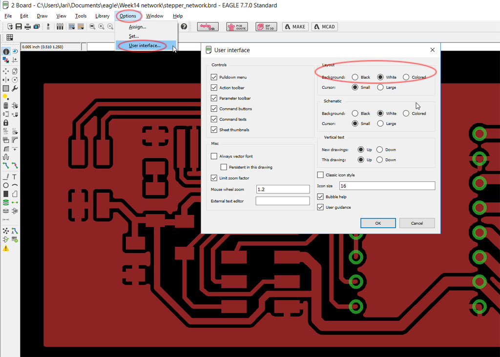
A .brd file is a native PCB layout file used by electronic design automation (EDA) software to store the physical board design of a printed circuit board. Unlike schematic files that represent logical connections, a .brd file defines the actual board geometry, copper routing, layers, drill data, footprints, and manufacturing constraints required for fabrication and assembly.
In practical terms, when an engineer finishes routing traces, placing components, defining stack-up layers, and setting design rules, that layout data is saved as a .brd file. It is the working design file—not the final manufacturing output like Gerber files.
What Is a .brd File?
A .brd file is the board layout file generated by certain Electronic Design Automation (EDA) tools. It stores the complete PCB layout environment, including:
- Board outline geometry
- Copper trace routing
- Via definitions
- Layer stack configuration
- Component footprints and placement
- Design rules and constraints
- Net connectivity
In simple terms:
- A schematic file (.sch) defines logical connections.
- A .brd file defines the physical realization of those connections.
The .brd file represents the stage where abstract circuitry becomes manufacturable hardware.

What Is the BRD File Format?
The BRD file format is proprietary and software-dependent. Different PCB tools use “.brd” as their internal layout database extension, but the internal structures are not interchangeable.
For example:
- Autodesk EAGLE uses .brd to store board layout data.
- Cadence Allegro also uses .brd as its main PCB database format.
- Mentor Graphics PADS historically used similar board database structures.
Although the file extension is identical, the file encoding, object hierarchy, and internal database schema vary significantly.
This means:
- An EAGLE .brd file cannot be directly opened in Allegro.
- An Allegro .brd file cannot be imported natively into EAGLE.
Therefore, when someone shares a .brd file, always confirm:
- Which software created it
- Which software version was used
Even minor version mismatches can cause compatibility issues.
Information Contained in a .BRD File
A .brd file is essentially the master PCB database. It contains nearly everything required to reproduce the board layout in a design environment.
1. Board Mechanical Definition
The file includes:
- Board outline dimensions
- Cutouts and slots
- Edge contours
- Mounting hole locations
- Keep-out regions
Mechanical integrity depends on these parameters. Incorrect outline data can lead to enclosure mismatch or assembly failure.
2. Layer Stack Definition
The layer stack is a critical element stored in the .brd file:
- Number of layers (2L, 4L, 6L, 10L, etc.)
- Signal layers
- Power/ground planes
- Dielectric spacing
- Copper thickness
In advanced designs such as HDI or high-speed boards, stack-up configuration affects:
- Impedance control
- Crosstalk performance
- EMI behavior
- Thermal dissipation
The .brd file stores these definitions so the design rules can reference them dynamically.
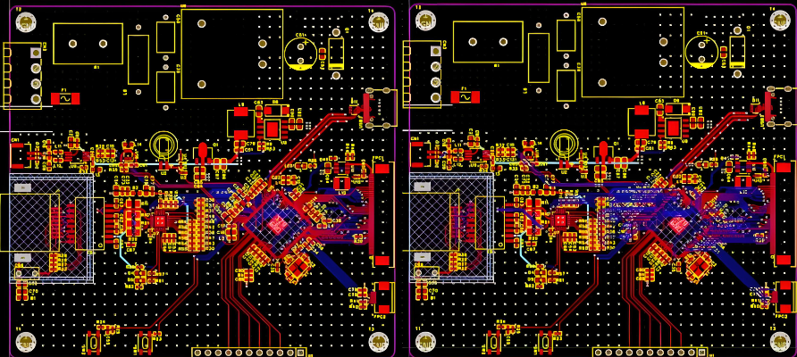
3. Copper Routing and Nets
The routing database inside a .brd file contains:
- Trace width
- Trace length
- Via types
- Differential pair constraints
- Length matching settings
In high-speed applications (DDR, PCIe, RF), this data is crucial. The .brd file tracks connectivity integrity in real time and allows DRC validation.
4. Component Placement Data
The file records:
- XY coordinates
- Rotation angles
- Layer (top/bottom)
- Reference designators
- Footprint library mapping
This placement information is later used to generate:
- Pick-and-place files
- Assembly drawings
- 3D board models
Without accurate placement data in the .brd file, assembly automation would be impossible.
5. Drill and Via Database
The .brd file includes:
- Through-hole vias
- Blind vias
- Buried vias
- Microvias
- Drill diameters
- Backdrill definitions
These parameters determine:
- Fabrication cost
- Reliability
- Yield rate
- Manufacturability
Advanced HDI structures rely heavily on precise via definitions stored inside the board file.
6. Design Rule Constraints
One of the most powerful aspects of a .brd file is its embedded DRC rules, including:
- Minimum trace width
- Clearance rules
- Solder mask expansion
- Annular ring requirements
- Impedance rules
- High-voltage spacing
These constraints prevent layout errors and ensure compliance with fabrication capability.
What Opens a .BRD File?
A .brd file must be opened using the software that created it or a compatible tool.
Common tools include:
- Autodesk EAGLE
- Cadence Allegro
- KiCad (import functionality available)
- Altium Designer (via import wizard)
Before opening a .brd file:
- Verify software origin
- Confirm version compatibility
- Check library dependencies
Missing footprint libraries can cause loading errors.
How to View .BRD File?
If editing is not required, viewing options include:
Option 1: Install Viewer Mode
Some PCB tools provide free viewing licenses.
Option 2: Convert to Neutral Format
Export:
- Gerber files
- ODB++
- IPC-2581
These can be viewed using standard PCB viewers.
Option 3: 3D Export
Many modern tools allow exporting a 3D STEP model for mechanical review.
In professional workflows, contract manufacturers rarely request the .brd file unless DFM modification is necessary. Instead, they prefer Gerber + drill + stack-up documentation.
Free BRD File Viewer
There is no universal free viewer because the format is proprietary.
However:
- Autodesk EAGLE offers limited viewing access.
- KiCad can import certain EAGLE board files.
- Cadence Allegro provides viewer licenses in enterprise environments.
For external sharing, converting to PDF or Gerber remains the safest method.
How Do I Open a BRD File on a Mac?
Mac compatibility depends on the originating tool.
Mac-supported tools:
- Autodesk EAGLE
- KiCad
Steps:
- Install compatible software
- Launch application
- Select File → Open
- Load the .brd file
If the file was created in a Windows-only environment such as Allegro, you may need virtualization or request exported files.
How to Import a BRD File?
Importing between platforms requires translation utilities.
1. Import EAGLE to KiCad
KiCad provides Eagle importer functionality:
File → Import → Eagle Project
2. Import EAGLE to Altium
Use the Import Wizard and select Eagle files.
After import:
- Run DRC
- Validate footprint mapping
- Check netlist integrity
- Reconfirm layer stack
Never assume automated translation is 100% accurate.
.BRD File vs Gerber File
| Aspect | .brd File | Gerber File |
| Type | Design database | Manufacturing output |
| Editable | Yes | No |
| Contains DRC rules | Yes | No |
| Software dependent | Yes | No |
| Used for fabrication | Indirectly | Directly |
The .brd file is like the “source code” of the PCB, while Gerber files are the “compiled output.”
.BRD File vs ODB++ and IPC-2581
Modern manufacturing increasingly uses intelligent formats.
- ODB++ stores full fabrication database.
- IPC-2581 is an open standard format.
Unlike Gerber, these formats contain stack-up, drill, and BOM references in a unified package.
The .brd file remains a design tool format, not a universal production format.
Why Manufacturers Rarely Need the .brd File?
From a fabrication perspective, manufacturers require:
- Copper layer data
- Drill data
- Stack-up definition
- Surface finish requirements
- Impedance control specs
All of these can be derived from Gerber + documentation.
Sharing .brd files may introduce:
- Intellectual property exposure
- Software compatibility challenges
- Version conflicts
Therefore, most manufacturers prefer standardized outputs.
How to Convert BRD File to PDF?
To convert a .brd file to PDF:
Method 1: Print to PDF
Open the board in the original software:
- File → Print
- Select “Print to PDF”
Method 2: Export Layers to PDF
Many PCB tools allow layer-by-layer PDF export.
Method 3: Export Gerber → Use Gerber Viewer → Export PDF
For professional documentation, designers typically generate:
- Assembly drawing PDF
- Fabrication drawing PDF
- 3D render export
EBest Circuit (Best Technology) – How We Support Engineer in PCB Design?
Understanding a .brd file is only the first step. Turning that design into a reliable, manufacturable PCB requires engineering validation, fabrication expertise, and controlled assembly processes.
Best Technology (EBest Circuit) supports customers from PCB layout verification to full turnkey PCBA production. If you have a .brd file and are unsure whether it is production-ready, our engineering team can assist with:
- Free DFM review and manufacturability analysis
- Stack-up optimization and impedance validation
- Drill structure and via reliability assessment
- Surface finish and material selection guidance
- Rapid PCB fabrication and PCBA assembly (prototype to mass production)
As a PCB + PCBA integrated manufacturer with over 20 years of experience, we help engineers convert design data into stable, repeatable production results. Whether your project involves HDI structures, heavy copper boards, high-speed digital layouts, RF applications, or industrial control systems, our technical team works directly with your design files to reduce risk before fabrication begins.
If you have a .brd file that needs professional review, quotation, or production support, feel free to contact us at: sales@bestpcbs.com
Our pre-sales engineering team typically responds within 12 hours to help move your project forward efficiently and confidently.