Rigid-flex copper substrate combines the best of both rigid PCBs and flexible circuits into a single circuit board. This design is both practical and innovative. Its applications range from advanced medical devices to aerospace systems. Its versatility stems from the way its copper layer is integrated with both flexible and rigid components, enabling smooth folding without disrupting connections.
Do you want to know:
- What are its advantages over ordinary substrates?
- How many frequent bends can it withstand?
- How is heat dissipation guaranteed?
- Does it support complex circuits and unusual shapes?
- What is the prototype production cycle?
- What are the quality standards?
BEST Technology, a professional metal-based circuit board manufacturer, can answer your questions:
- The high heat dissipation of a rigid substrate combined with the flexibility of a flexible substrate allows for complex applications.
- Dynamic bending resistance of ≥100,000 times (R=1mm) ensures continuous circuitry and stable performance.
- Highly conductive adhesive layer combined with a full copper surface design results in a thermal resistance of ≤0.8°C/W, improving heat dissipation by 30%+ in high-temperature environments.
- Minimum line width/spacing of 3 mils, supports unusual shapes and stepped structures, and an accuracy error of ≤±0.1 mil.
- Prototypes take 3 days, and mass production takes 7-15 days. Compliant with IPC-A-600H, with over 20 tests and 24-hour customer service.
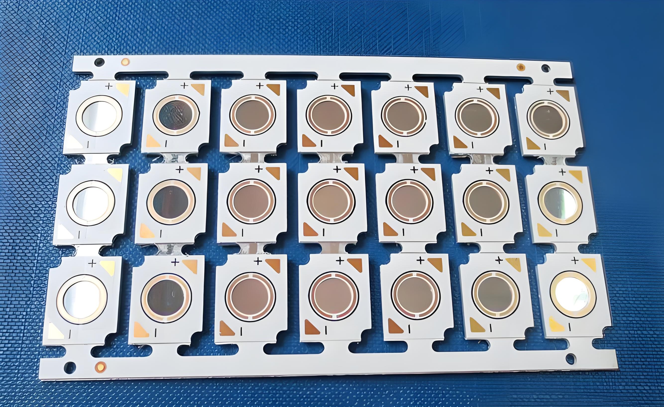
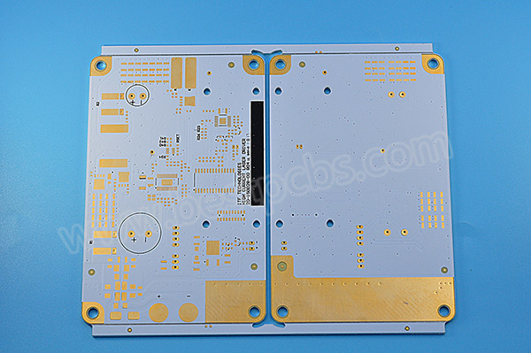
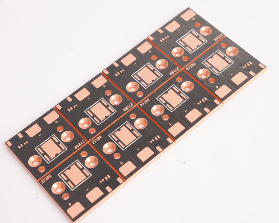
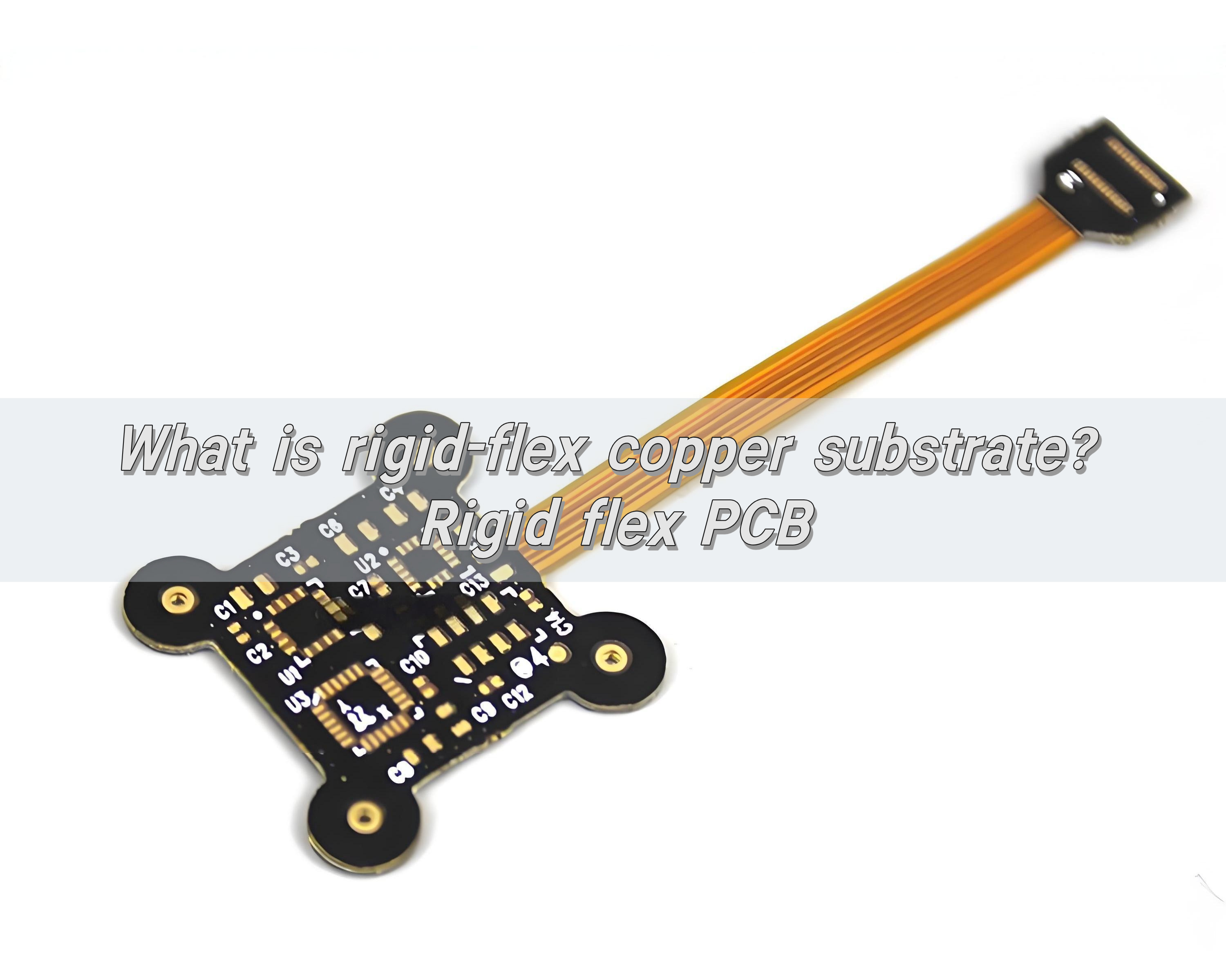
What is rigid-flex copper substrate?
Rigid-flex copper substrate is a hybrid printed circuit board that has rigid and flexible layers combined into one structure. The rigid parts provide mechanical stability, while the flexible layers connect them, allowing bending or folding during assembly or use.
This combination removes the need for connectors or separate ribbon cables, reducing the risk of signal loss or failure. In many designs, rigid-flex boards improve reliability and performance at the same time.
The rigid flex PCB design typically uses copper foil as the conductor. Copper is preferred because it offers excellent conductivity, mechanical strength, and resistance to fatigue. The result is a board that can bend without losing electrical integrity.
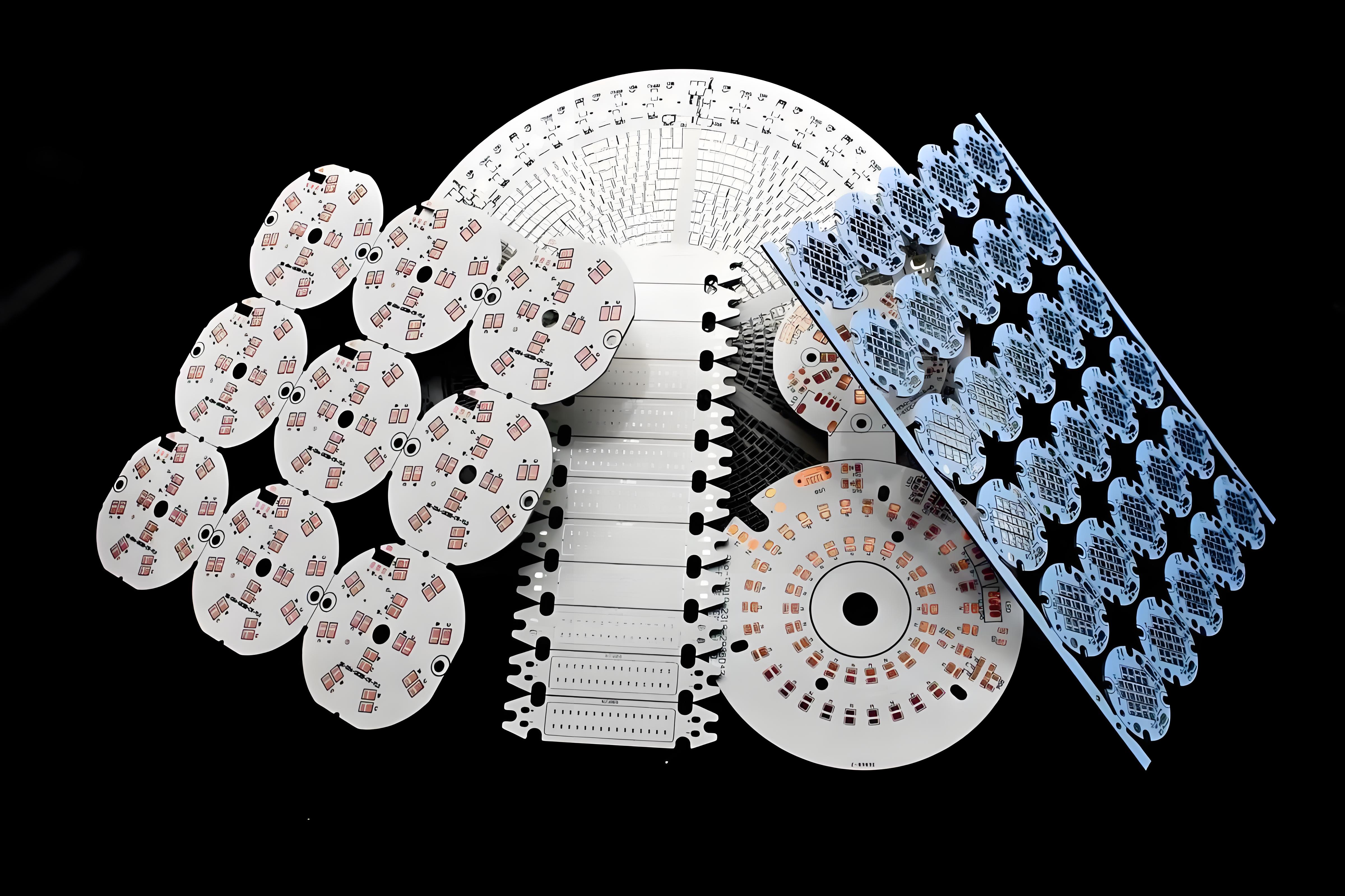
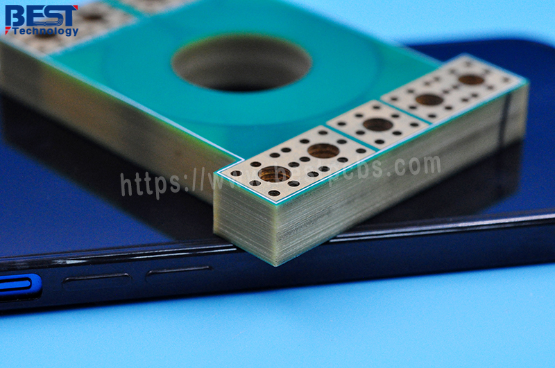
Rigid-flex copper substrate with different layers
Layer count in a rigid-flex board greatly impacts performance, cost, and applications.
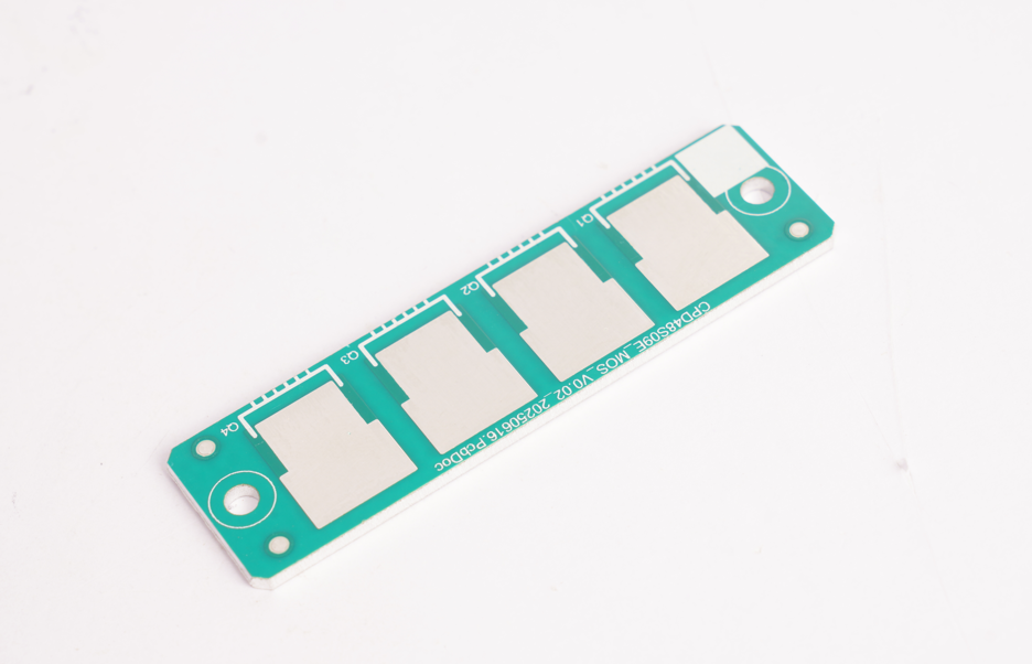
- 1. 2-layer rigid-flex copper substrate
This is the simplest form. It offers enough flexibility for basic designs and is often used in consumer devices, portable gadgets, and small control panels. It’s affordable and fast to produce.
- 2. Dual-layer rigid-flex copper substrate
Similar to the 2-layer version but often built with reinforced materials. It provides more strength and is ideal for designs that require slight bending during use.
- 3. 4-layer rigid-flex copper substrate
With more copper layers, it allows complex routing, better signal performance, and improved EMI shielding. The 4-layer copper-based rigid-flex PCB is common in automotive electronics and handheld medical devices.
- 4. 6-layer rigid-flex copper substrate
This high-end design is built for advanced technology. It supports multiple high-speed signals, complex interconnections, and precise impedance control. Aerospace systems, industrial control machines, and military electronics often use this type.
Choosing the right layer count depends on design needs, available space, and budget. Each option balances performance and flexibility differently.
How does rigid flex PCB work?
The rigid flex PCB works by integrating multiple circuit layers—some rigid, some flexible—into one laminated structure. During manufacturing, the flexible layers are bonded with polyimide material, while the rigid parts are reinforced with FR4 or other stiffeners.
When installed, the flexible sections bend to fit inside tight enclosures. This makes it perfect for 3D assembly. The electrical signals flow through copper traces that remain continuous across the rigid and flexible areas, eliminating the need for connectors.
By reducing interconnections, rigid flex PCBs lower the risk of mechanical failure, improve signal speed, and make products more reliable in harsh conditions.
Why choose rigid-flex copper substrate?
There are many reasons to choose a rigid-flex copper substrate.
- Space efficiency: This design allows components to be placed closer together, reducing product size.
- Durability: Flexible sections handle repeated bending without breaking. This is important in devices exposed to motion or vibration.
- Improved performance: Fewer connectors mean faster signal transmission and less interference.
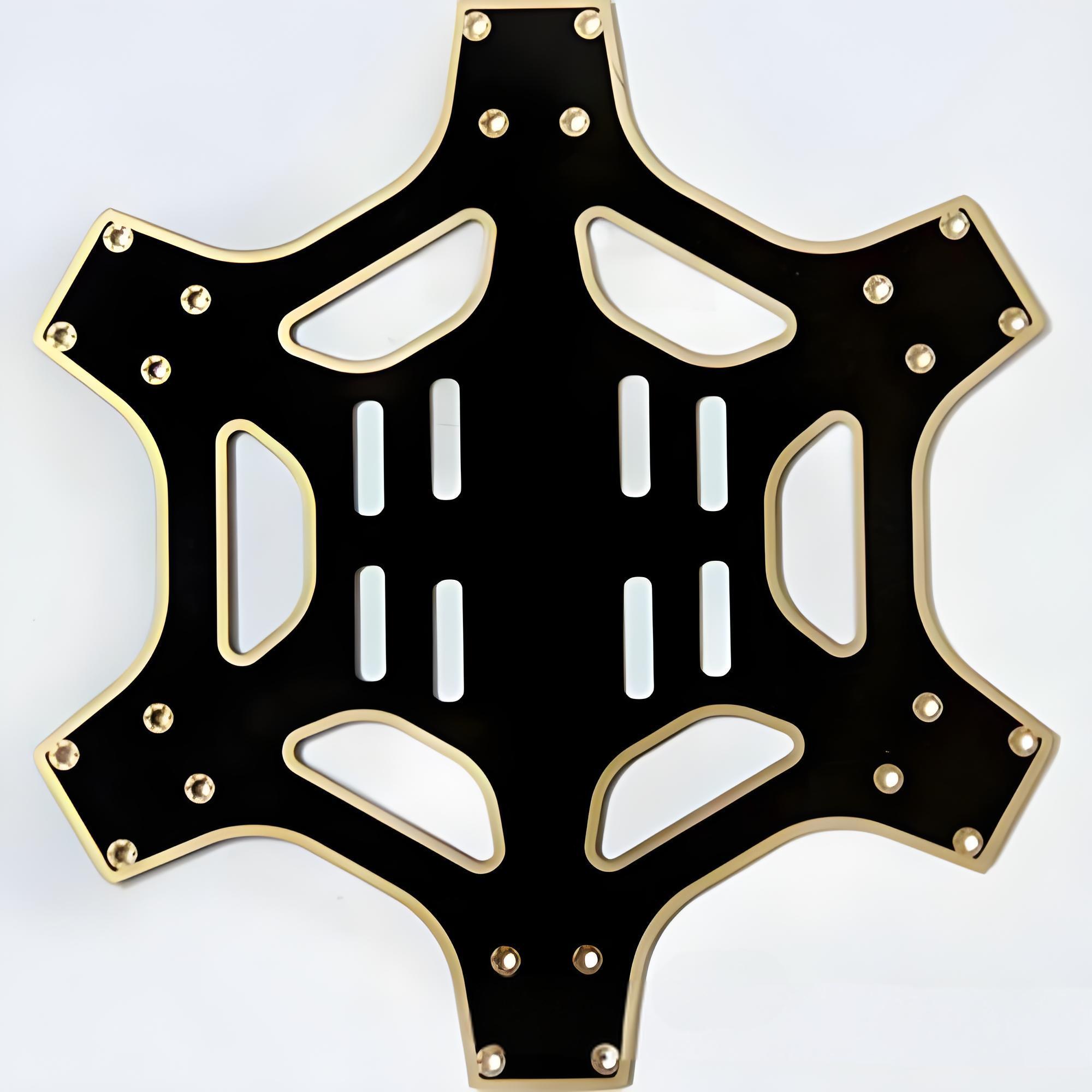
- Lightweight construction: Replacing multiple boards and cables with one unit cuts down weight.
- Design freedom: Three-dimensional design is possible, allowing for better utilization of interior space.
From smartphones to satellites, rigid-flex boards help achieve higher performance without increasing size.
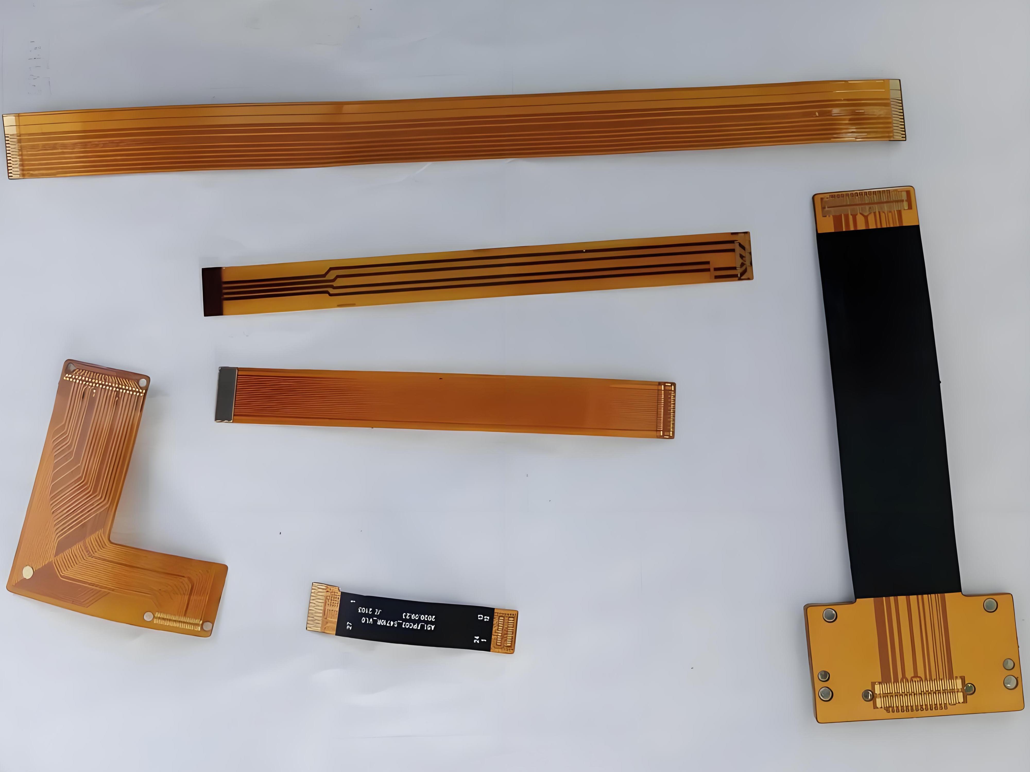
Which flexible PCB material is best?
The performance of a rigid-flex PCB depends heavily on the flexible material. Most use flexible circuit technologies with polyimide films, which offer excellent heat resistance, flexibility, and electrical insulation.
Polyimide is also stable in harsh environments, making it a trusted choice for aerospace, automotive, and industrial applications. For added strength, some designs use adhesive-less laminates, which improve bending capability and reduce thickness.
Copper foil is the heart of the conductor. Rolled annealed copper is preferred for its flexibility and fatigue resistance, while electro-deposited copper works well for more rigid applications.
The choice of flexible PCB material depends on the final product’s environment, electrical needs, and mechanical requirements.
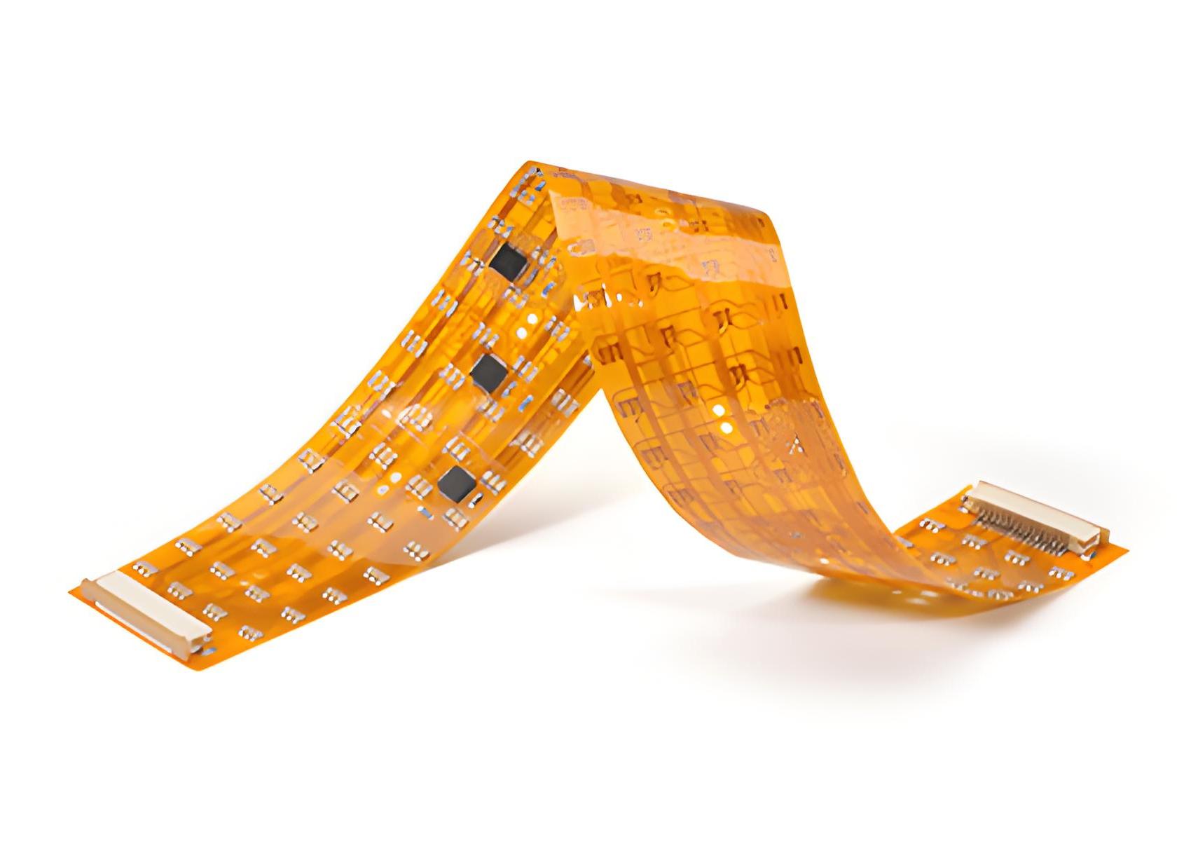
How durable is flexible PCB material?
Flexible PCB materials are surprisingly tough. High-quality polyimide can handle thousands of flex cycles without cracking. Even in high-temperature or high-vibration environments, it maintains structural integrity.
Durability also depends on copper type, layer thickness, and protective coatings. Protective coverlays shield copper traces from moisture, dust, and abrasion. When designed correctly, a rigid-flex PCB can last as long as the device itself.
It’s worth noting that durability is not just about materials—it’s also about design. Proper bend radius, trace routing, and reinforcement all increase lifespan.
How does rigid flex PCB save space?
One of the biggest advantages of rigid-flex PCBs is their space-saving ability. By combining rigid and flexible sections into one board, you remove the need for bulky connectors and cables.
This allows components to be stacked closer or arranged in creative ways. Devices can be slimmer, lighter, and easier to assemble. For example, in wearables or medical implants, every millimeter counts. The space saved often translates directly into more battery capacity, extra features, or lighter designs.
For manufacturers, fewer components mean faster assembly and fewer points of failure.
What affects rigid-flex copper substrate cost?
Cost can vary widely depending on several factors:
- Layer count: More layers mean more complex manufacturing, which increases price.
- Material choice: Premium copper foils and polyimide films cost more but offer better performance.
- Size and shape: Complex shapes require more precise processing.
- Production volume: Higher quantities often reduce per-unit cost.
- Testing requirements: Rigid-flex boards for aerospace or medical devices require strict quality control, adding to cost.
Working with a skilled flex PCB manufacturer ensures cost efficiency without compromising quality. BEST Technology will help you choose the best PCB stackup, optimize the number of layers, and select the most suitable flexible PCB material for your needs.
Need Rigid-Flex Copper Substrate? BEST Technology can help you, contact sales@bestpcbs.com