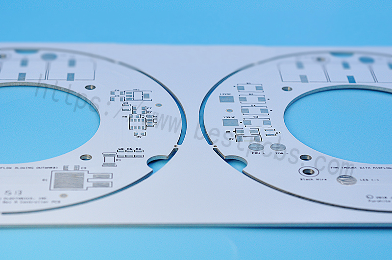
Metal Core Printed Circuit Board (short for MCPCB) is a technology developed to overcome the thermal limitations of the FR4 Printed Circuit Board. Different with traditional FR4 PCB, the PCB uses FR4 material as base core, while the base material of a metal core PCB is aluminum or copper. So compared with FR4 PCB, Metal Core is a better choice if your boards need to perform in high temperature environment.
What is metal core PCB?
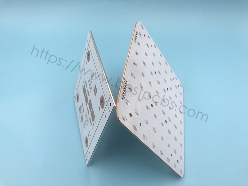
A Metal Core PCB (MCPCB), also known as a thermal PCB or metal backed PCB, is a type of PCB that a metal material as its base for the heating dissipation part of the board. The thick metal is covering one side or double side of the PCB. The purpose of the core of a MCPCB is to redirect heat away from critical board components (such as LED or IC chips), and to less crucial areas such as the metal heatsink backing or metallic core. Base metals in the MCPCB are used as an alternative material to FR4 boards.
Same as FR4 PCB, the metal core PCB can be divided into Single layer MCPCB, Double layers MCPCB and Multi-layer MCPCB.
- Single layer MCPCB
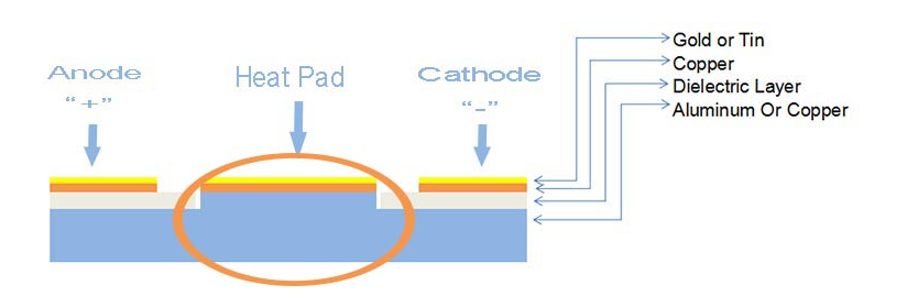
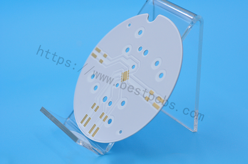
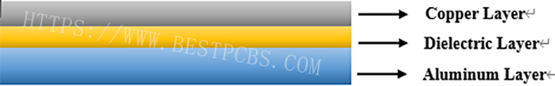
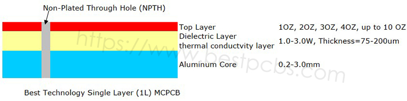
A single layer MCPCB is consist of a metal base (usually aluminum or copper alloy), thermal conductivity/dielectric layer and a copper trace layer, you can check below stack up for more details. Due to it only has one layer copper trace, sometimes we called it as one-layer MCPCB or single sided MCPCB.
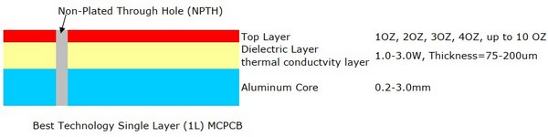
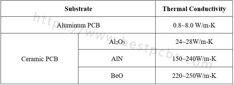
The single sided MCPCB can be used with surface mount and chip & wire components, and provides much lower thermal resistance than FR4 PCB. What’s more, the metal core provides lower cost than ceramic substrates, and allows much larger areas than ceramic substrates.
Meanwhile, superior heat dissipation and good durability of Aluminum of metal core PCB can greatly eliminate heat sinks or other some voluminous hardware for engineers or designers.
- Double layer MCPCB
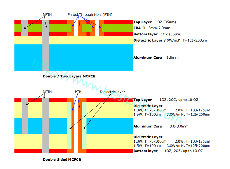
Double layers MCPCB (2L MCPCB) has two copper layers on one side of PCB, and metal core as a base core on the bottom side of whole MCPCB, so the components only can be populated on the top side, below is a structure of double layer MCPCB.
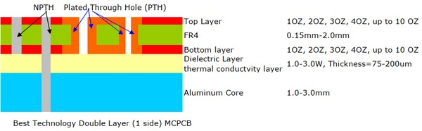
From the stack up of double layers MCPCB, we can see it consists of a single layer MCPCB and a double sided FR4 PCB, so it needs an additional pressing process to laminate the thermal conductivity and FR4 PCB. Compared with normal FR4, this structure needs more technology and experience on laminating of two layers together with metal core.
There are two layers copper trace on the surface of MCPCB, can we call it as double sided MCPCB like single layer MCPCB?
The answer is NO, because they have different structure and perform different properties. In our next post, we will show you the differences between double sided MCPCB and 2 layers MCPCB.
- Multi-layer MCPCB
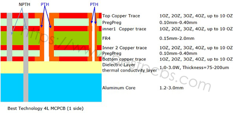
Same as FR4 PCB, for those copper traces more than 2 layers, we named them Multi-layer MCPCB. Its structure is same as FR4 PCB, but more complex to fabricate. Below is a typical stack up of a 4 layers MCPCB:

Contrast with single layer or double layers MCPCB, multi-layer MCPCB can populate more components and achieve better performance in electronical performance.
Why Choose Metal core PCB?
Metal core PCB offers a great list of advantages when apply in a high-power application, below we listing some benefits of it:
- Excellent heat dissipation
- Lower thermal expansion than FR4 PCB
- Dimensional stability than polyimide FPC
- Great durability
- Long lifetime
- High utilization rate of space due to the heating can be transferred quickly
- High strength and lightweight than FR4 PCB
- Cost-effective
Where can we use Metal core PCB?
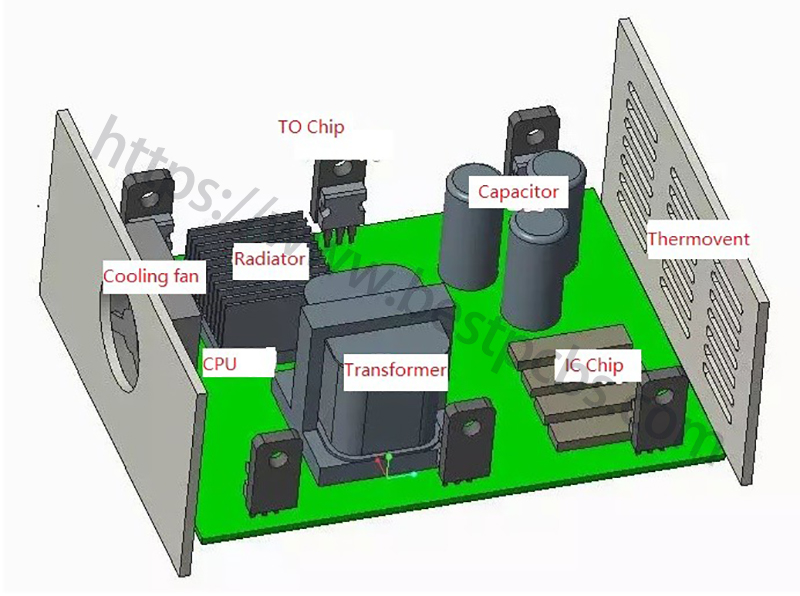
Metal core PCB can be used in high-power filed where requires fast cooling, good heat dissipation characteristics, the following popular applications may give you a guideline:
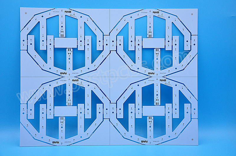
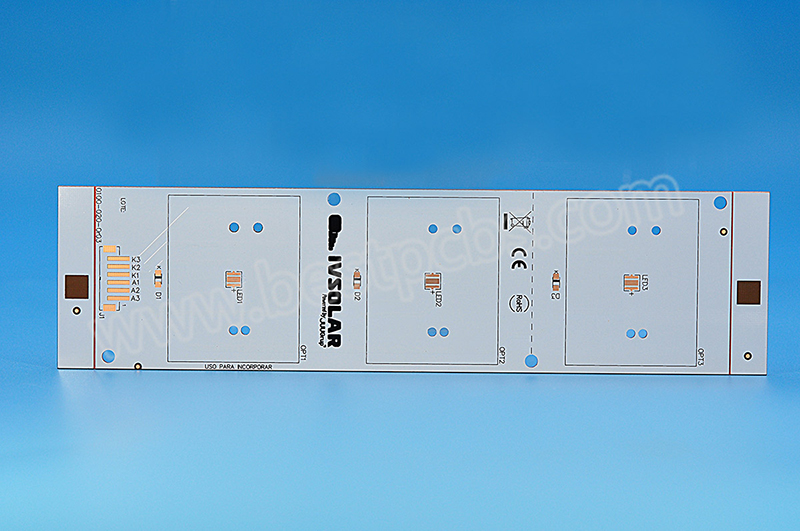
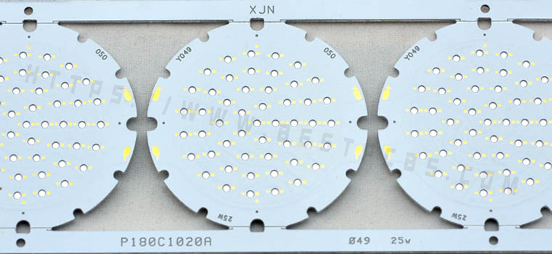
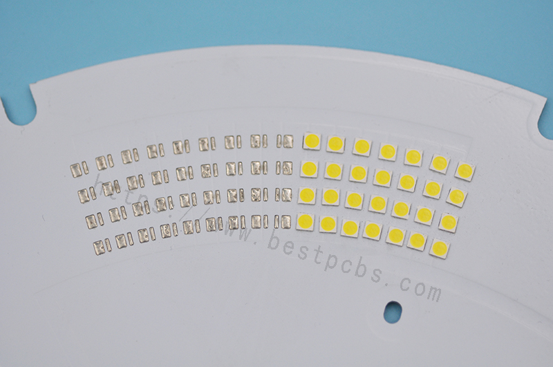
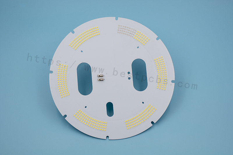
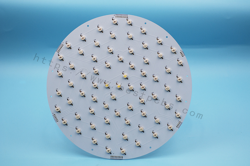
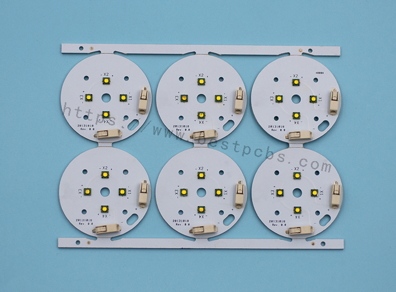
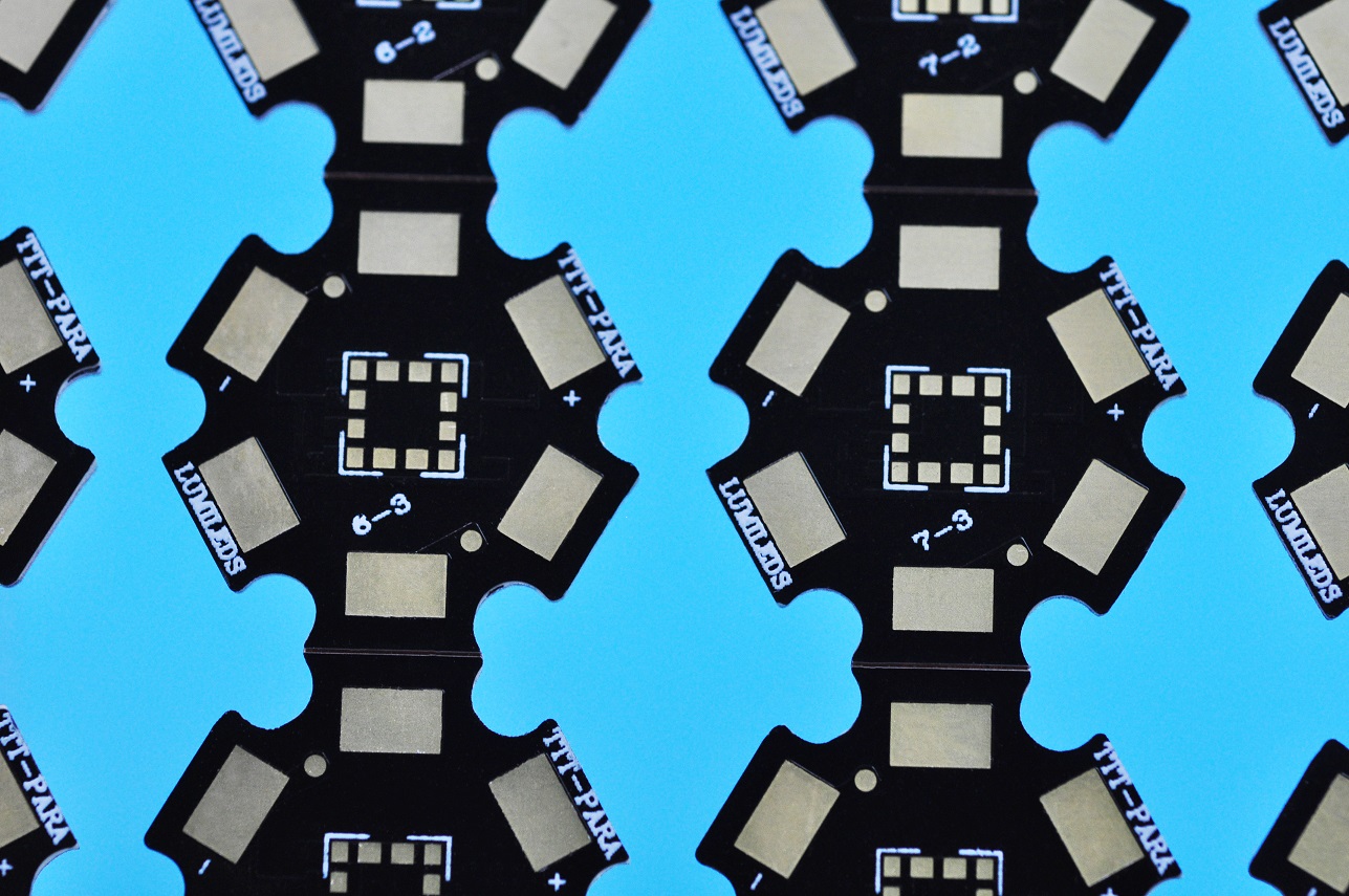
- LED lighting
- Power suppliers
- Power conversion system
- Automotive electronics
- Telecom industrial
- Photovoltaics
- Semiconductors
With more than 16 years manufacturing experience, EBest Circuit (Best Technology) is one of MCPCB supply leaders in Asia with good metal core PCB capability, we are so confident that we can provide you high quality, fast delivery and excellent one-stop service. Warm welcome to contact us if you have inquiries.