Need ultra-compact micro LED PCB solutions? Explore addressable round boards with precision control, rigorous testing, and mini LED advantages.
EBest Circuit (Best Technology) redefines speed and precision in addressable micro LED round PCB manufacturing. Our 24-hour rapid prototyping service gets your samples ready for testing while maintaining 50μm ultra-fine pitch accuracy for high-density arrays. We deliver 20% cost savings compared to industry standards through optimized smart manufacturing processes. Every order includes complimentary DFM analysis by our engineering team to eliminate design risks before production. With ISO-certified facilities and proprietary thermal management technology, we achieve 30% better heat dissipation than conventional designs. Over 150 successful micro LED display projects demonstrate our expertise in delivering pixel-perfect solutions. Benefit from free sample evaluation within 72 hours and volume discounts starting at 100pcs. Get instant quotes with 12-hour response time and dedicated technical support throughout your product lifecycle. Feel free to contact us if you have any request for micro LED PCB: sales@bestpcbs.com.
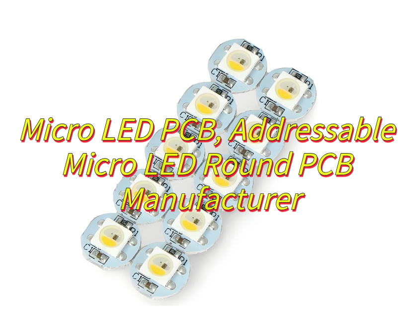
What Is Micro LED PCB?
A micro LED PCB is a specialized circuit board engineered for mounting and interconnecting microscopic light-emitting diodes (LEDs), typically under 100μm in size. These advanced boards feature ultra-high-density layouts with micron-level trace precision to support thousands of individual Micro LED chips, often arranged in matrix configurations for next-generation displays. Constructed using thermally conductive substrates like aluminum or ceramics, they efficiently dissipate heat from densely packed LED arrays while maintaining structural stability. The PCB incorporates specialized solder masks and fine-pitch copper traces to prevent electrical interference between adjacent micro-components. Unlike conventional LED boards, Micro LED PCBs require sub-micron assembly accuracy to ensure pixel uniformity, often integrating thin-film transistors or embedded drivers for active matrix control. This technology enables self-emissive displays with superior brightness, wide color gamut, and energy efficiency compared to LCD or OLED solutions, making it ideal for high-resolution applications including AR/VR headsets, premium TVs, and commercial video walls.
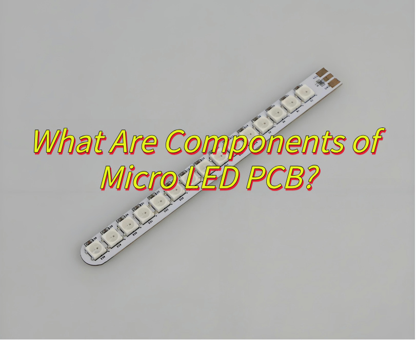
What Are Components of Micro LED PCB?
Here are the essential components of a micro LED PCB:
- Micro LED Chips – Microscopic light-emitting diodes typically under 100μm in size, serving as individual pixel elements with self-emissive properties.
- High-Density Substrate – Specialized base material (often aluminum or ceramic) providing thermal management and structural support for dense LED arrays.
- Fine-Pitch Copper Traces – Ultra-thin conductive pathways precisely routing electrical signals between Micro LEDs with micron-level accuracy.
- Solder Mask Layer – Protective coating preventing electrical shorts between densely packed components while allowing precise solder placement.
- Thermal Interface Materials – Heat-dissipating compounds managing temperature distribution across the LED matrix.
- Embedded Driver Circuits – Integrated control elements (TFTs or ICs) enabling individual pixel addressing in active matrix configurations.
- Optical Enhancement Films – Light management layers improving viewing angles and color uniformity in display applications.
- Protective Overlay – Transparent cover shielding delicate Micro LED structures from environmental factors.
- Interconnection Pads – Microscopic contact points facilitating electrical bonding between LEDs and circuit traces.
- Alignment Markers – Precision reference points ensuring sub-micron accuracy during chip placement.
- Power Distribution Network – Optimized conductive grid delivering stable voltage to all LED elements.
- Signal Conditioning Components – Passive elements (resistors/capacitors) maintaining signal integrity across the array.
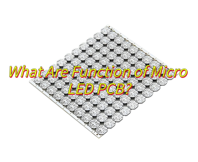
What Are Function of Micro LED PCB?
Functions of micro LED PCB:
- Electrical Interconnection and Signal Transmission: Micro LED PCBs serve as the backbone for delivering electrical signals to individual Micro LED chips. By integrating intricate circuitry, they ensure precise voltage and current distribution across dense arrays of Micro LEDs, enabling synchronized light emission and high-resolution imagery.
- Thermal Management: The compact design of Micro LED displays generates significant heat during operation. Advanced PCBs incorporate thermal vias, copper layers, and heat-dissipating materials to regulate temperature, preventing performance degradation and extending the lifespan of Micro LED components.
- Mechanical Support and Structural Integrity: Micro LED PCBs provide a rigid substrate to mount fragile Micro LED chips, protecting them from physical stress, vibrations, and environmental factors. This structural role is critical for maintaining alignment and durability in ultra-thin or flexible display formats.
- High-Density Pixel Integration: By leveraging miniaturized traces and microvia technology, Micro LED PCBs enable the placement of thousands to millions of Micro LEDs per square inch. This density supports ultra-high-definition displays (e.g., 8K resolution) with minimal pixel pitch.
- Power Efficiency Optimization: PCBs designed for Micro LED applications often include power management circuits that reduce energy loss. Features like localized voltage regulation and low-resistance pathways ensure efficient power delivery, critical for battery-operated devices such as smartwatches or AR glasses.
- Driver Circuit Integration: Micro LED PCBs may embed active matrix drivers (e.g., thin-film transistors or CMOS backplanes) to control each pixel’s brightness and color independently. This integration eliminates the need for external drivers, simplifying system design and reducing latency.
- Optical Performance Enhancement: Surface treatments on PCBs, such as blackened coatings or reflective layers, improve light extraction efficiency from Micro LEDs. These optimizations minimize light absorption and crosstalk between adjacent pixels, enhancing contrast and color accuracy.
- Scalability for Diverse Form Factors: Whether for large video walls, wearable devices, or automotive displays, Micro LED PCBs adapt to varying sizes and shapes. Flexible PCB variants enable curved or foldable displays, while rigid-flex hybrids support complex 3D geometries in automotive HUDs or lighting systems.
- Reliability in Harsh Environments: Industrial or automotive Micro LED PCBs incorporate moisture-resistant coatings, high-temperature-resistant laminates, and corrosion-resistant metals to ensure stability under extreme conditions, such as high humidity, UV exposure, or thermal cycling.
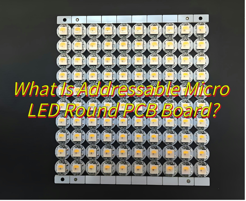
What Is Addressable Micro LED Round PCB Board?
An addressable micro LED round PCB board is a circular circuit platform integrating microscale light-emitting diodes (typically <100µm pitch) with individually controllable pixels, constructed on specialized substrates (aluminum/glass/ceramic). It combines radial copper trace patterns with active matrix driving circuits, enabling precise per-pixel luminosity adjustment through embedded CMOS controllers. The architecture employs hybrid interconnect methods including micro-solder bumps and anisotropic conductive adhesives to bond LED arrays, while maintaining signal integrity across curved geometries through impedance-matched annular routing. Thermal management integrates phase-change materials and micro-patterned heatsinks to counteract concentrated heat generation in rotational symmetric layouts. Manufacturing processes involve laser-guided pick-and-place systems for angular chip alignment and electroplated redundancy paths to ensure operational continuity. Primary applications span 360° wearable displays, automotive HUD rings, and endoscopic imaging systems where circular form factors and pixel-level programmability enable novel optical configurations. The design confronts challenges in maintaining uniform current density across radial power buses and compensating for thermal expansion mismatches in multi-material assemblies during high-frequency operation.
How to Select An Addressable Micro LED Round PCB Manufacturer?
How to select an addressable micro LED round PCB manufacturer:
- Assess Technical Expertise in Micro LED Integration: Verify the manufacturer’s experience in integrating addressable Micro LED chips onto circular PCB substrates. Look for specifics on their capability to handle pixel-level precision, thermal management, and uniform light distribution across curved or radial layouts. Request case studies or technical whitepapers demonstrating past projects with similar complexity.
- Evaluate PCB Design and Layout Proficiency: Circular PCBs require advanced design skills to optimize trace routing, minimize signal loss, and ensure mechanical stability. Assess whether the manufacturer uses specialized software tools (e.g., Altium, Eagle) for circular board design and can address challenges like annular ring placement, via positioning, and impedance control in non-rectangular geometries.
- Inquire About Driver IC and Control System Compatibility: Addressable LEDs demand precise synchronization between PCB hardware and control software. Confirm the manufacturer’s familiarity with industry-standard driver ICs (e.g., WS2812B, APA102) and their ability to customize firmware for seamless communication with microcontrollers or LED control systems. Request a demonstration of their debugging process for address mapping or signal integrity issues.
- Review Quality Control Processes: Micro LEDs are sensitive to defects like dead pixels or solder joint failures. Prioritize manufacturers with rigorous quality assurance protocols, including automated optical inspection (AOI), X-ray testing for solder joints, and burn-in tests under extreme temperatures. Ask about their defect rate metrics and rework procedures for non-conforming units.
- Examine Material Selection and Durability: Circular PCBs for LED applications often require substrates with high thermal conductivity (e.g., metal-core PCBs) or flexible materials (e.g., polyimide) for curved installations. Evaluate the manufacturer’s understanding of material properties, such as CTE (coefficient of thermal expansion) matching between LED chips and PCB substrates to prevent warping or delamination over time.
- Consider Scalability and Production Capacity: If your project requires volume manufacturing, assess the manufacturer’s production line capabilities. Inquire about their panelization strategies for circular boards (e.g., array layouts on rectangular panels to minimize material waste) and their ability to scale from prototype to mass production without compromising quality.
- Check for Industry Certifications and Compliance: Ensure the manufacturer adheres to relevant standards such as IPC-A-600 (PCB acceptance criteria), ISO 9001 (quality management), and RoHS/REACH compliance for environmental safety. For applications in harsh environments (e.g., outdoor lighting), confirm their expertise in conformal coating or IP-rated enclosure integration.
- Analyze Cost Structure and Value Engineering: Compare pricing models while considering hidden costs like tooling fees, setup charges, or per-unit pricing for low-volume vs. high-volume orders. Look for manufacturers willing to propose value engineering solutions, such as component substitution or design simplification, to reduce costs without sacrificing performance.
- Probe Post-Production Support and Iteration Speed: A reliable manufacturer should offer post-production support, including failure analysis, root cause diagnostics, and quick-turn prototyping for design iterations. Ask about their average lead times for revisions and their policy on handling obsolete components or supply chain disruptions.
- Leverage Third-Party Reviews and References: Request references from previous clients, particularly those with projects involving addressable LEDs or circular PCBs. Analyze independent reviews or industry benchmarks to gauge the manufacturer’s reputation for reliability, communication, and adherence to deadlines.
How Do We Test and Validate Addressable Micro LED Round PCB Performance?
How to test and validate addressable micro LED round PCB performance:
Electrical Functionality Verification
- Use a precision multimeter or automated test equipment (ATE) to measure voltage/current parameters across individual LED nodes. Confirm that power supply rails meet specified voltage tolerance (e.g., ±5%) under maximum load conditions.
- Validate addressability by sequentially activating LED segments using a microcontroller or signal generator. Check for cross-talk or unintended activation in adjacent channels.
- Test current uniformity with a programmable DC power supply, ensuring current deviation between LEDs does not exceed ±3% to maintain consistent brightness.
Thermal Management Assessment
- Apply continuous full-power operation for 48–72 hours while monitoring temperature distribution using an infrared thermal camera. Identify hotspots near high-density LED clusters or driver components.
- Validate heat dissipation efficiency by comparing junction temperature rise (ΔTj) against thermal simulation models. Ensure compliance with maximum operating temperature limits (e.g., ≤85°C for consumer-grade components).
Mechanical Durability Testing
- Conduct vibration testing per MIL-STD-202 standards using an electrodynamic shaker. Simulate transportation and operational vibrations (10–500 Hz, 2G amplitude) to detect solder joint fatigue or PCB delamination.
- Perform bend testing by clamping the PCB edges and applying controlled radial force to assess flexibility limits. Document deflection thresholds before structural failure occurs.
Optical Performance Evaluation
- Measure luminous flux and color consistency using an integrating sphere coupled with a spectroradiometer. Verify that color coordinates (CIE 1931) match specified bins (e.g., Δu’v’ ≤0.005) and luminance uniformity exceeds 90% across the circular array.
- Test angular emission characteristics with a goniophotometer. Confirm beam angle specifications (e.g., ±10° deviation from design targets) and detect optical coupling issues between adjacent LEDs.
Environmental Stress Screening
- Subject PCBs to temperature cycling (-40°C to +125°C, 100 cycles) and humidity exposure (85% RH, 85°C, 168 hours) in a climate chamber. Monitor electrical continuity and addressability post-exposure to identify moisture ingress or material degradation.
- Perform corrosion resistance testing using salt spray chambers (5% NaCl, 48 hours) for applications in marine or high-humidity environments.
Signal Integrity Analysis
- Validate data transmission reliability using a time-domain reflectometer (TDR). Measure impedance continuity (target ±10% of 50Ω) across PCB traces to minimize signal reflections.
- Test electromagnetic interference (EMI) compliance with a spectrum analyzer. Ensure radiated emissions stay below FCC Part 15 or equivalent limits through proper shielding and grounding.
Long-Term Reliability Assessment
- Accelerated life testing (ALT) under elevated temperature (e.g., 60°C ambient with 1.2× rated current) to extrapolate MTBF (mean time between failures) using Arrhenius equation models.
- Monitor LED lumen maintenance over 10,000+ hours using a photometer. Verify that output degradation remains below 30% per LM-80 standards for the intended application lifespan.
Assembly and Mounting Compatibility
- Validate mechanical attachment methods (e.g., screw holes, press-fit pins) through torque testing and pull-strength measurements. Ensure retention force exceeds 20N for secure installation.
- Test conformal coating adhesion using cross-hatch tape testing per ASTM D3359. Confirm no delamination occurs after 50 thermal cycles.
Power Efficiency Benchmarking
- Calculate overall system efficiency by measuring input power vs. total luminous flux output. Compare results against theoretical models to identify energy loss pathways (e.g., driver losses, thermal waste).
- Optimize PWM (pulse-width modulation) dimming ranges. Verify linearity and flicker-free operation down to 1% duty cycle using an oscilloscope with high-speed photodetector.
User Safety Compliance
- Confirm insulation resistance between conductive layers (>100 MΩ at 500V DC) using a hipot tester.
- Validate flame retardancy per UL 94 V-0 standards through vertical burning tests on PCB substrate samples.
Can Our LED Microcontroller PCB Integration Support Real-Time Addressable Control?
Yes, the integration of an LED microcontroller PCB can support real-time addressable control, provided specific technical requirements are met. Below is a detailed breakdown of the enabling factors and implementation considerations:
Microcontroller Performance Requirements
- Processing Speed: The microcontroller must have sufficient clock frequency (e.g., ≥72 MHz for ARM Cortex-M series) to handle LED data parsing, protocol decoding, and output refresh cycles within the required latency window (typically <10 ms for visual smoothness).
- Memory Capacity: Adequate RAM (e.g., ≥32 KB) is needed to buffer LED state data, especially for large arrays. Flash memory should accommodate the control algorithm and communication stack.
- Peripheral Interfaces: Hardware modules like SPI, I2C, or UART with DMA support are critical for parallel data transmission to LED drivers, minimizing CPU intervention.
Addressable LED Protocols
- Single-Wire Protocols: WS2812B/SK6812 LEDs use a timing-specific protocol requiring precise bit-banging (e.g., 800 kHz data rate). Microcontrollers with programmable I/O (e.g., STM32’s PWM timers) can achieve this.
- Multi-Wire Protocols: APA102/DotStar LEDs use a 2-wire SPI-like interface, which is more tolerant of timing variations and easier to implement with standard peripherals.
- Custom Protocols: For specialized applications, a microcontroller can implement proprietary addressing schemes via GPIO multiplexing or shift registers.
Real-Time Operating System (RTOS) Considerations
- Task Prioritization: An RTOS (e.g., FreeRTOS) ensures LED control tasks preempt lower-priority processes, maintaining deterministic latency.
- Interrupt Handling: Low-latency interrupts for communication peripherals (e.g., SPI completion interrupts) prevent data bottlenecks.
- Memory Management: Static allocation avoids fragmentation risks in time-critical applications.
Hardware Design Optimizations
- PCB Layout: Differential signaling or controlled impedance traces minimize EMI and signal degradation for high-speed data lines (e.g., >10 MHz for SPI).
- Power Distribution: Dedicated voltage regulators and decoupling capacitors prevent flicker from power supply noise.
- Level Shifting: 3.3V-to-5V logic converters ensure compatibility with LED drivers if the microcontroller operates at lower voltages.
Scalability and Refresh Rates
- Parallel Data Channels: Using multiple SPI/I2C ports or DMA chains allows simultaneous updates of LED segments, scaling to thousands of nodes.
- Frame Rate Calculation: For a 1,000-LED strip at 24-bit color depth, a 30 FPS refresh rate requires ~72 kbps throughput—achievable with SPI at 10+ MHz.
Error Mitigation Strategies
- CRC/Checksum: Implement data integrity checks for critical applications (e.g., stage lighting).
- Redundant Channels: Backup communication paths prevent single-point failures.
- Watchdog Timers: Automatic system resets prevent lockups from software glitches.
What Are Difference Between Micro LED PCB and Mini LED PCB?
Differences Between Micro LED PCB and Mini LED PCB
LED Chip Size and Density
- Micro LED PCB: Utilizes LED chips smaller than 100 micrometers (μm) in diameter, enabling extremely high pixel density (often exceeding 10,000 pixels per inch). This allows for ultra-fine image rendering and seamless integration in compact displays.
- Mini LED PCB: Employs LED chips ranging from 100 μm to 300 μm. While smaller than traditional LEDs, they are larger than Micro LEDs, resulting in lower pixel density but still superior to conventional LCD backlighting.
Display Performance
- Micro LED PCB: Achieves exceptional brightness (up to 10,000 nits or higher), infinite contrast ratio (due to self-emissive pixels), and true black levels. It supports wider color gamuts and faster response times, making it ideal for high-end professional displays and AR/VR devices.
- Mini LED PCB: Enhances LCD performance by using thousands of local dimming zones, improving contrast ratios (up to 1,000,000:1) and HDR capabilities. However, it still relies on a backlight system, limiting black levels compared to Micro LED.
Power Efficiency and Heat Dissipation
- Micro LED PCB: Highly energy-efficient due to direct pixel-level emission, reducing power consumption by up to 50% compared to Mini LED. Smaller chip size also minimizes heat generation, simplifying thermal management.
- Mini LED PCB: Requires more power for backlighting arrays, leading to higher operational heat. Advanced cooling solutions (e.g., graphite sheets, vapor chambers) are often necessary to maintain stability.
Manufacturing Complexity and Cost
- Micro LED PCB: Involves precision processes like mass transfer of tiny chips, which are technically challenging and expensive. Yield rates remain low, driving up production costs significantly.
- Mini LED PCB: Leverages mature LED packaging techniques, reducing manufacturing barriers. While still pricier than traditional LCDs, it is more cost-effective than Micro LED at scale.
Application Scenarios
- Micro LED PCB: Targets premium markets such as transparent displays, wearable devices, and automotive HUDs. Its modular design also suits large-format video walls and custom shapes.
- Mini LED PCB: Widely adopted in consumer electronics like high-end TVs, gaming monitors, and laptops. It bridges the gap between affordable LCDs and premium OLEDs.
Durability and Lifespan
- Micro LED PCB: Boasts a lifespan exceeding 100,000 hours, with no risk of burn-in due to inorganic materials. Resistant to environmental factors like humidity and temperature fluctuations.
- Mini LED PCB: Offers similar longevity to traditional LEDs (60,000–100,000 hours) but may face minor degradation in backlight uniformity over time.
Design Flexibility
- Micro LED PCB: Enables ultra-thin, flexible, and even stretchable displays due to chip-level miniaturization. Suitable for unconventional form factors like curved or foldable screens.
- Mini LED PCB: Limited to rigid or slightly curved designs, as backlight layers add thickness. Flexibility is constrained by PCB substrate materials.
Market Maturity
- Micro LED PCB: Still in early commercialization, with limited availability in niche products. Mass adoption hinges on cost reductions and yield improvements.
- Mini LED PCB: Rapidly gaining traction, with multiple brands launching Mini LED-backlit devices. Expected to dominate the premium display segment in the near term.
In conclusion, while both technologies represent advancements in display innovation, Micro LED PCB excels in performance and versatility but faces cost and scalability hurdles. Mini LED PCB offers a pragmatic balance between cost and performance, making it a transitional solution toward wider adoption of self-emissive displays.