What is chip on board? Chip-on-board packaging is a process that directly adheres the bare chip to the PCB, connects the electrical signal through wire bonding or flip chip, and finally encapsulates it with protective materials. It is commonly used in consumer electronics, automotive electronics, industrial control and other fields.
What is Chip-on-Board (COB)?
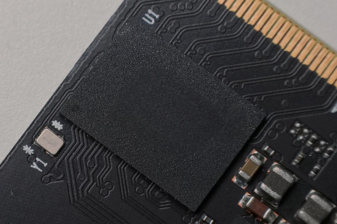
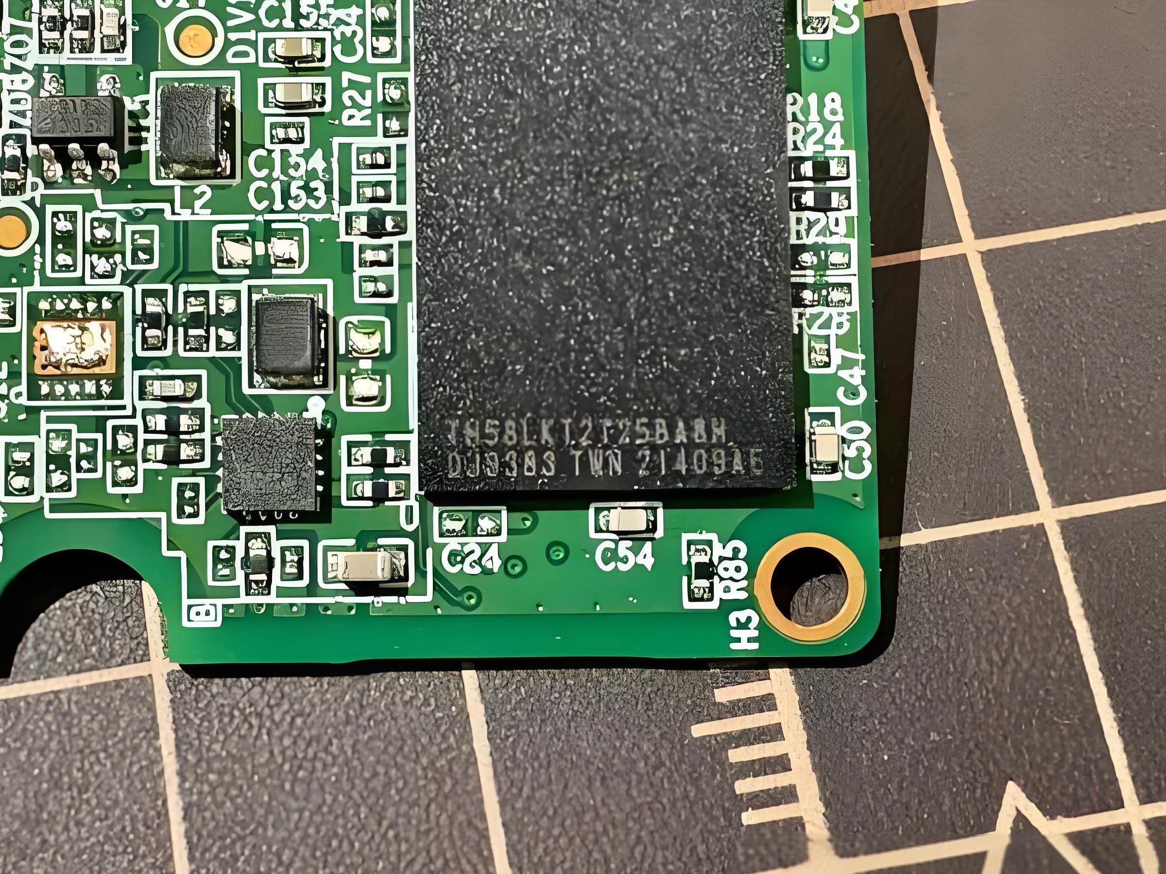
Chip-on-Board (COB) is an advanced packaging technology that directly mounts semiconductor chips onto a printed circuit board (PCB) or substrate. The chips are then covered with an epoxy glob-top to protect them from environmental damage.
COB technology enhances performance, reduces size, and improves thermal management, making it ideal for LEDs, sensors, and high-density electronic circuits. It is widely used in consumer electronics, industrial applications, and medical devices.
COB technology simplifies circuit design by eliminating traditional chip packaging, making electronic devices more compact and efficient. This method also allows for a higher density of chips on a single board, improving overall system performance.
Additionally, COB reduces signal interference, as the shorter wiring distances lead to faster signal transmission with minimal loss.
How to Make a Chip-on-Board?
The COB manufacturing process starts with substrate preparation. The substrate must be cleaned thoroughly to remove dust and contaminants before the die is attached.
Once the die is secured using conductive epoxy or eutectic bonding, precision wire bonding is performed using high-speed automated equipment.
The encapsulation process follows, where the chip is covered with an epoxy resin or silicone coating to protect it from moisture, dust, and mechanical damage.
After curing, functional tests ensure that the COB performs as expected before being integrated into devices.
What is the Process of Chip-on-Board Assembly?
COB assembly follows a structured procedure:
- Die Attachment – The semiconductor die is placed onto the PCB or ceramic substrate using epoxy or eutectic bonding.
- Wire Bonding – Tiny gold or aluminum wires connect the die pads to the board’s circuit.
- Encapsulation – A protective resin, covers the chip to prevent oxidation and mechanical damage.
- Testing & Inspection – Each COB unit undergoes electrical testing to ensure proper functionality.
This streamlined process enhances durability and performance while reducing space requirements. COB technology eliminates the need for bulky component packaging, making it ideal for high-density applications.
In high-volume production, automated optical inspection (AOI) and X-ray inspection methods are used to detect defects at an early stage. These techniques improve quality control and reduce failure rates.
The encapsulation step can vary based on the application, with some requiring clear resin for optical applications like LED modules, while others use opaque coatings for protection in industrial environments.
What is the Material of Chip-on-Board?
COB technology primarily uses:
- Substrate Materials: FR4, ceramic, or metal-core PCBs
- Die Attach Adhesives: Epoxy resins or solder materials
- Wire Bonding Materials: Gold (Au) or aluminum (Al) wires
- Encapsulation: Epoxy or silicone resin
Each material is chosen to optimize thermal conductivity, reliability, and performance. The choice of substrate depends on the specific application requirements.
Ceramic substrates, such as aluminum oxide (Al₂O₃) or aluminum nitride (AlN), are commonly used for high-power applications due to their superior thermal conductivity.
Metal-core PCBs (MCPCBs) are another option, particularly in LED applications, where efficient heat dissipation is critical.
The selection of wire bonding materials also plays a crucial role in the performance of COB assemblies, with gold wires offering excellent conductivity and oxidation resistance, while aluminum wires provide a cost-effective alternative.
What Does a Chip-on-Board Do?
COB improves circuit efficiency by integrating chips directly onto the board. This minimizes electrical resistance and enhances heat dissipation.
COB is widely used in LED applications, automotive electronics, medical devices, and consumer electronics. By eliminating traditional chip packaging, COB enhances performance while reducing costs.
COB technology is essential in miniaturized electronic devices, where space is a premium. It allows for higher functionality in a compact form factor, enabling the development of advanced applications such as wearable devices, biomedical implants, and high-speed communication systems.
The improved electrical performance of COB results in lower power consumption and higher reliability, making it suitable for mission-critical applications.
What Are the Advantages of Chip-on-Board?
COB offers several benefits:
- Compact Design: Reduces overall device size.
- Better Thermal Management: Direct chip-to-substrate contact improves heat dissipation.
- Enhanced Performance: Shorter electrical paths enhance speed and efficiency.
- Lower Production Costs: Eliminates the need for traditional packaging.
- Improved Reliability: Protective coating shields against dust, moisture, and impact.
- Higher Power Density: Ideal for high-performance applications requiring intense power output.
In addition to these advantages, COB also provides improved electromagnetic interference (EMI) performance.
Since the chip is mounted closer to the PCB, the overall signal path is shorter, reducing noise and improving signal integrity. This feature makes COB technology suitable for high-speed computing and RF communication applications.
Moreover, COB enables flexible and custom design options, allowing manufacturers to optimize layouts based on specific application needs.
How Does Chip-on-Chip Work?
Chip-on-Chip (CoC) is a stacking technology where multiple dies are placed on top of each other. This differs from COB, where chips are directly attached to the PCB.
CoC enhances computing power and is widely used in high-performance processors and memory modules.
CoC technology is often found in mobile devices, high-speed computing, and AI processors.
CoC is commonly used in multi-core processors, DRAM memory modules, and advanced image sensors. This technology enables efficient use of real estate on circuit boards, reducing latency and improving overall system performance.
Thermal management in CoC designs is critical, requiring advanced cooling solutions such as thermal vias and integrated heat spreaders.
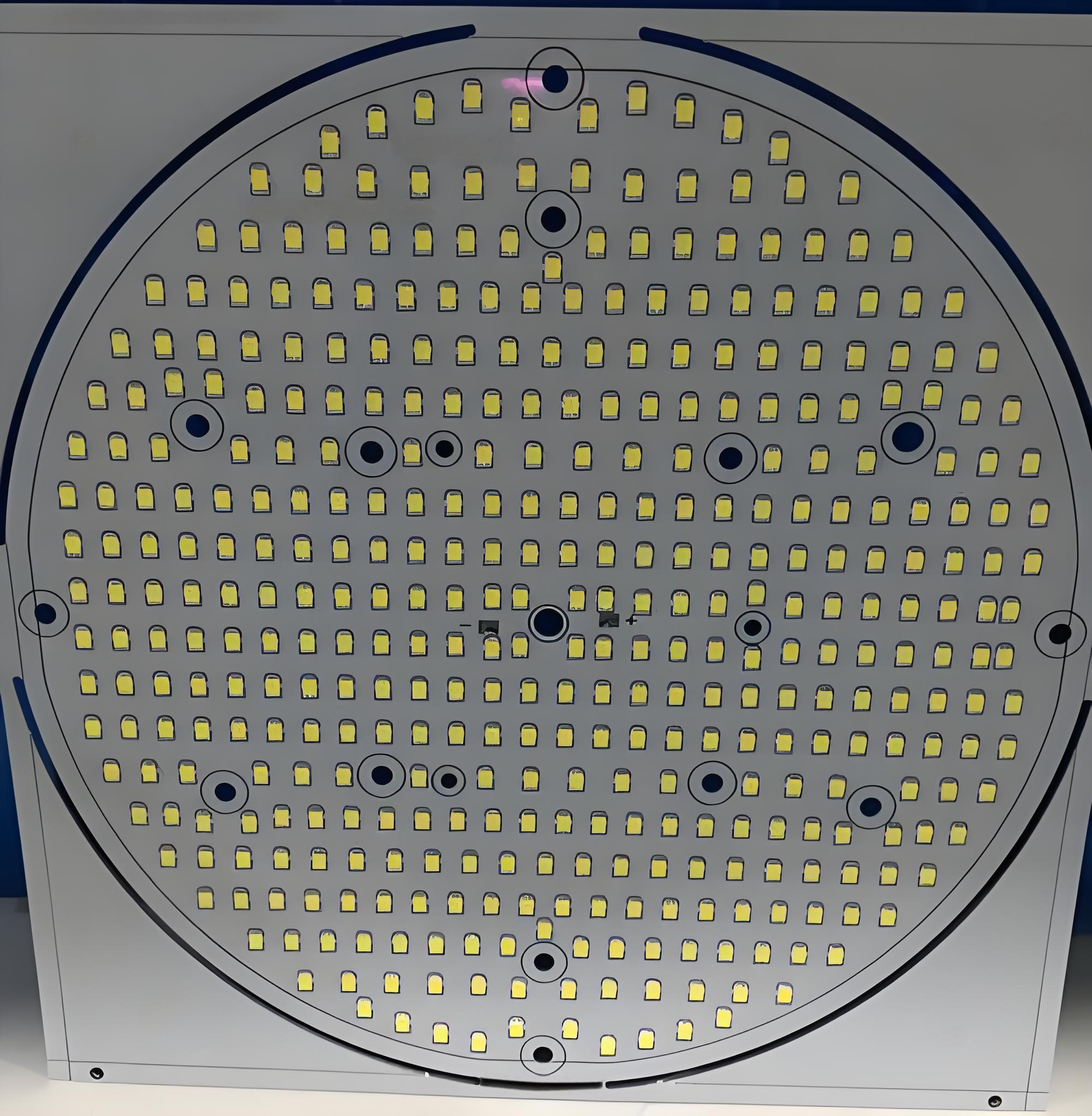
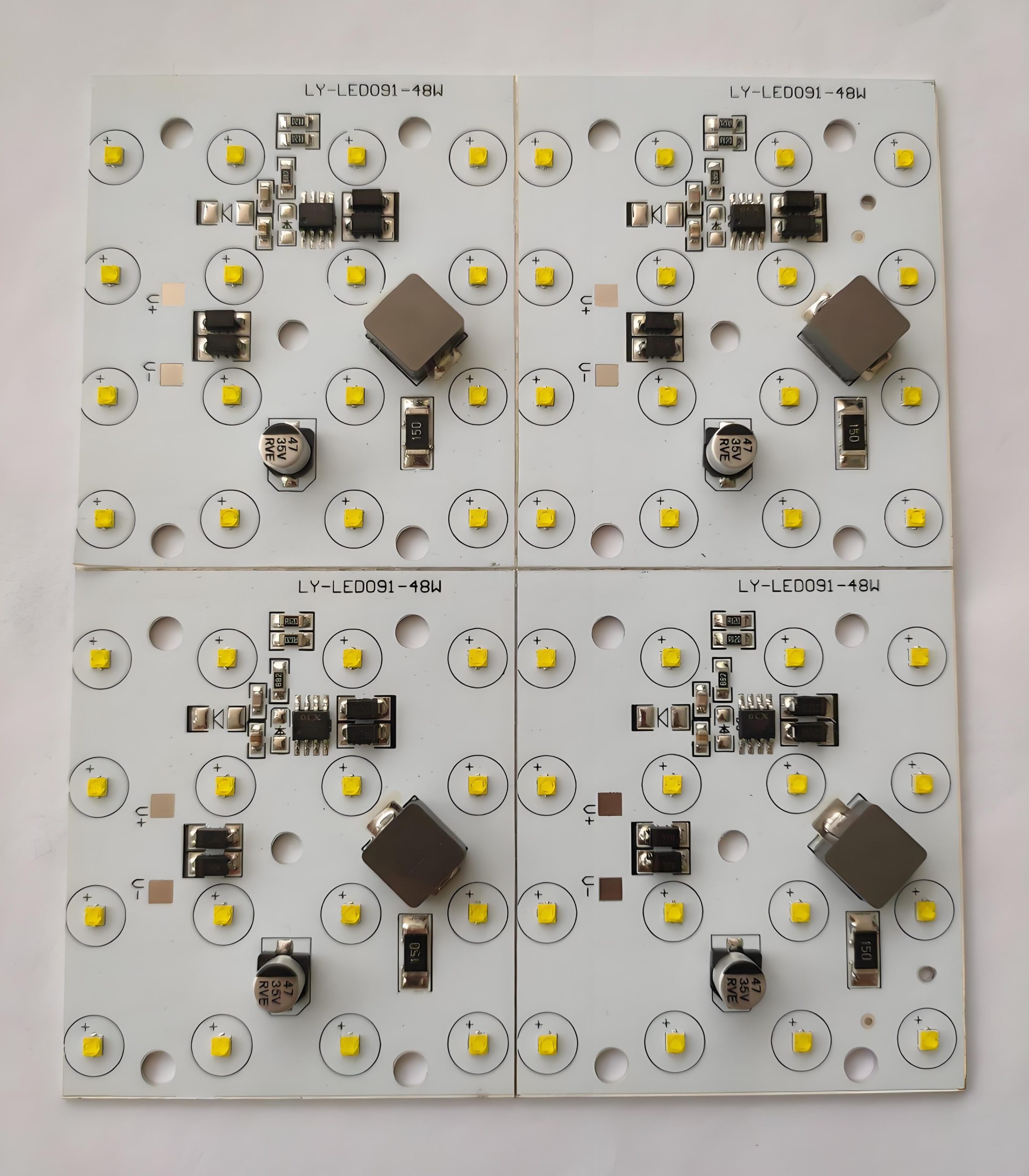
What is Chip-on-Board LED?
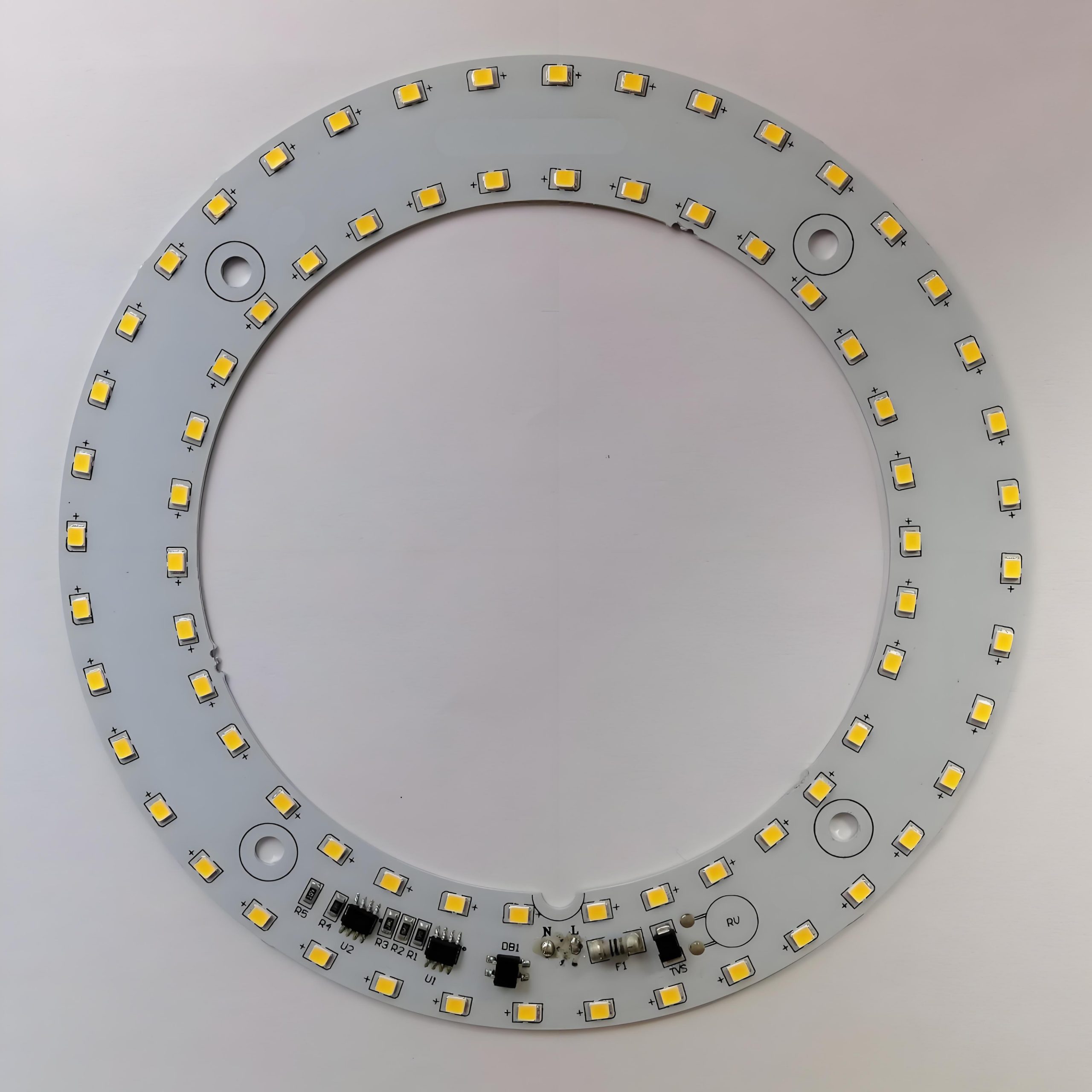
COB LED technology integrates multiple LED chips onto a single substrate. This creates a high-intensity light source with uniform illumination. COB LEDs are commonly used in:
- COB LED Strips: Flexible lighting solutions with consistent brightness.
- COB LED Grow Lights: Efficient plant-growing illumination.
- COB LED Panels: High-output lighting for commercial use.
COB LEDs outperform traditional LEDs in brightness and heat dissipation. They are ideal for industrial, automotive, and commercial lighting applications.
COB LEDs are designed for high-efficiency applications, offering better lumen output per watt compared to traditional surface-mount device (SMD) LEDs. Their broad beam angle provides uniform light distribution, making them ideal for downlights, floodlights, and stadium lighting.
The compact nature of COB LEDs also allows for innovative designs, such as ultra-thin panel lights and high-intensity projectors.
What is the Difference Between PCB and COB?
A PCB is the foundation for electronic circuits, providing mechanical support and electrical connections for components. It can house surface-mounted or through-hole components. Traditional PCBs require additional chip packaging, leading to larger designs.
In contrast, COB (Chip-on-Board) technology eliminates chip packaging by mounting the semiconductor die directly onto the PCB. This method offers a more compact, high-performance alternative with better thermal management.
COB technology is especially beneficial for LED applications, sensors, and advanced electronics where space and efficiency are critical.
While standard PCBs cater to general electronics, COB is ideal for high-density applications requiring superior power efficiency and miniaturization.
COB technology reduces electrical resistance, shortens signal paths, and improves heat dissipation, making it a preferred choice for industries demanding high reliability and performance.
Conclusion:
COB technology revolutionizes modern electronics by improving efficiency, reducing costs, and enhancing performance. EBest Circuit (Best Technology) ensures top-tier quality in every COB and PCB solution, for inquiries, contact us at sales@bestpcbs.com