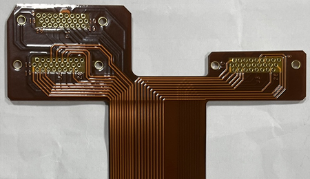
Recently, Best Technology faced a huge challenge in a 2oz copper rigid flex PCB manufacturing, this board appeared simple on the drawing but revealed multiple layers of engineering challenges once entering mass production. But finally, we finished this project very well and overcome this challenge, let’s see what are the challenges on this project and how does our team overcome them!
Project Introduction
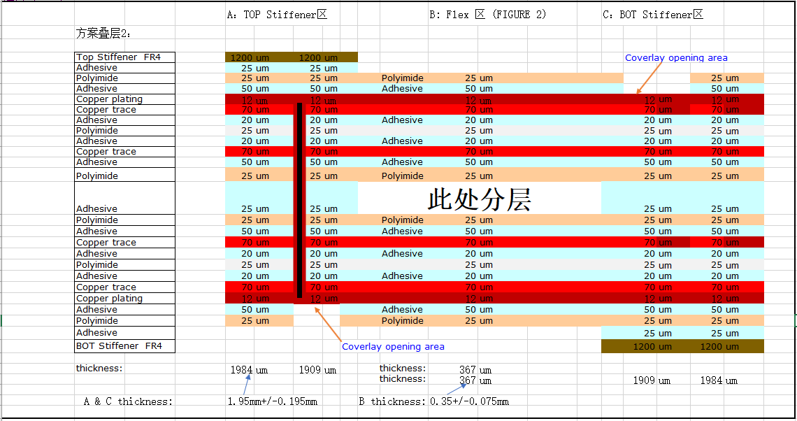
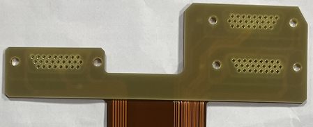
The board used a 70/25 double-sided adhesive ED flexible substrate with PI25/AD50 coverlay, coupled with a 2+2 layers dual access structure that required thick copper, small annular rings, narrow spacings, and FR4 stiffeners with extremely limited clearance. Each of these parameters independently creates difficulty, but combined, they demand precise collaboration between engineering, fabrication, and process control.
This article explains:
Why the design was inherently difficult
What manufacturing risks were present
How our engineering team solved each challenge
What PCB designers should avoid in similar projects
Flexible substrate: 70/25 double-sided adhesive ED copper
Coverlay: PI 25 µm + Adhesive 50 µm
Base copper: 2 oz copper
Layer count: Four-layer rigid-flex structure
Critical routing: 0.15 mm minimum trace/space
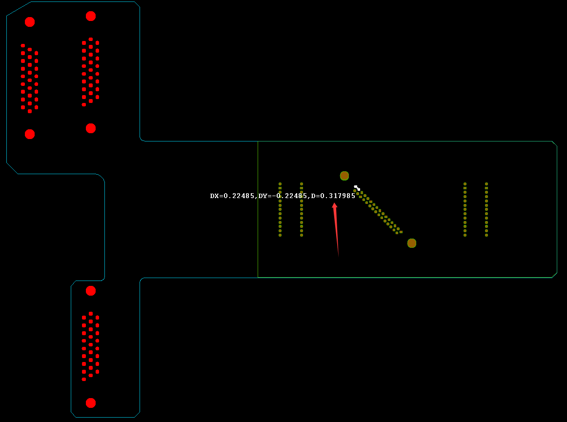
Plated hole: 0.66 mm with hole spacing of only 0.60 mm
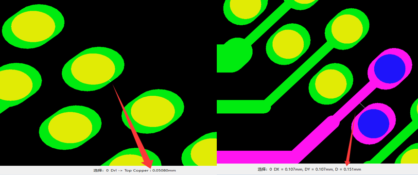
Annular ring: 0.05 mm on certain pads
Stiffener: FR4 stiffener with 0.95 mm stiffener hole and 0.31 mm ribs
This combination is common in advanced HDI rigid-flex PCB manufacturing, yet its manufacturability depends heavily on copper behavior, adhesive flow, and drilling tolerances.
Why This Rigid-Flex PCB Was Inherently Difficult?
1. Thick copper increases side-etching risk
With 2 oz copper, the etching rate is higher and lateral etch—often called side-etch—is harder to control. In this case, the side-etching amount reached: 0.0070 ± 0.003 mm. For ultra-fine traces in a rigid-flex PCB design, this will eat into the design margin.
2. Small annular rings compromise via reliability
Pads with 0.05 mm annular ring severely restrict drilling tolerance. In flex-rigid PCB fabrication, annular rings below 0.10 mm are classified as high-risk features.
3. Extremely tight stiffener clearance
The stiffener needed:
±0.20 mm placement tolerance
±0.05 mm drilling tolerance
But the designer only left 0.15 mm clearance, causing a mismatch between rigid-flex PCB stiffener alignment tolerance and actual manufacturing capability.
4. Thin FR4 stiffener ribs cause glue overflow
Ribs only 0.31 mm wide cannot allow adhesive to retreat during bonding, causing pure glue to overflow and block the stiffener holes.
Technical Challenge #1: Thick Copper Etching with Narrow Spacing
A 2 oz thick copper PCB combined with:
0.15 mm trace/space
0.05 mm annular ring
0.66 mm PTH
creates a situation where compensation is unavoidable.
However, after compensation (~0.007 mm), the remaining trace width would drop to:
0.08 mm (0.15 – 0.07 mm)
This is below the safe manufacturability range of most rigid-flex PCB suppliers.
Best Technology’s solution
Eliminated compensation on 0.15 mm traces
Implemented fine-tuned etching control
Maintained ~0.10 mm final copper width
Ensured full electrical reliability
This is a proven strategy in advanced rigid-flex PCB manufacturing for thick-copper builds.
Technical Challenge #2: Annular Ring Integrity in Plated Through Holes
Annular rings <0.10 mm are extremely vulnerable to:
Drill wander
Etching undershoot
Copper thinning
This is especially critical in high-reliability rigid-flex PCBs, where via integrity is essential.
Best Technology’s solution
Applied rigid-board-level PTH plating process
Improved copper thickness inside the via barrel
Adjusted drilling control to 0.65 ± 0.075 mm
Customer accepted partial ring breakage as long as electrical integrity remained intact
This ensured consistent via performance even in ultra-dense rigid-flex PCB layouts.
Technical Challenge #3: Stiffener Bonding, Alignment, and Adhesive Overflow
1. Why stiffener tolerance was problematic
In rigid-flex PCB assembly, stiffeners are critical for mechanical reinforcement. However:
Hole spacing was only 0.60 mm
Stiffener clearance only 0.15 mm per side
Combined tolerance ±0.25 mm
This inevitably leads to the stiffener covering the pads unless advanced alignment controls are used.
2. Why glue overflow occurs
Thin ribs (0.31 mm) cannot provide an escape path for adhesive. During lamination:
The glue squeezes into the holes
Holes become blocked
Boards fail inspection
3. Best Technology’s engineered solution
Pre-laminated pure adhesive onto FR4 stiffener
Re-drilled stiffener holes after bonding
Greatly reduced glue overflow
Added 100% AOI + manual inspection for hole clearing
Rejected defective boards, shipped only fully passing units
This is a common best practice in flex PCB stiffener processing when tolerances are tight.
DFM Guidelines for Rigid-Flex PCB Designers
Avoid annular rings under 0.15 mm, especially in 2 oz copper flex-rigid PCB design.
Avoid combining thick copper with fine lines, this will increase manufacturing risk.
Ensure stiffener clearance > total tolerance stack-up. If your clearance is smaller than the alignment tolerance, the stiffener will inevitably shift.
Keep stiffener ribs ≥0.5 mm
Send your design for DFM review before finalizing. A goodrigid-flex PCB manufacturer will help adjust the stack-up, drill size, and stiffener layout to avoid expensive redesigns.
This case demonstrates how a complex rigid-flex PCB—with 2 oz copper, ultra-fine traces, small annular rings, and extreme stiffener constraints—can be successfully manufactured through detailed engineering, advanced process control, and disciplined quality screening.
Best Technology combines strong fabrication capability with practical DFM insight, enabling customers to produce compact, reliable, and manufacturable rigid-flex PCB designs that perform consistently under demanding conditions.
If you need support with your next rigid-flex or flex PCB project, our engineering team is ready to assist with stack-up review, DFM checks, or trial builds.
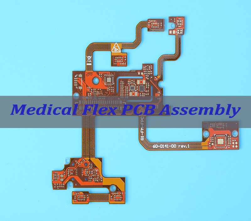
Flex PCB assembly represents a revolutionary approach to electronic circuitry that enables bending and folding to fit compact medical devices. This technology transforms how we design everything from implantable pacemakers to advanced imaging systems by replacing rigid boards and bulky wiring with flexible, reliable alternatives. This guide explores the complete landscape of medical flex PCB assembly, from fundamental concepts to specialized manufacturing considerations for life-critical applications.
Why do medical device manufacturers struggle with implementing reliable flex PCB solutions?
Key Pain Points:
Ensuring reliability in life-critical medical applications where failure is not an option
Achieving miniaturization for implantable and wearable devices without sacrificing performance
Navigating complex medical regulatory requirements and certification processes
Managing higher initial costs while maintaining uncompromised quality
Preventing failures in dynamic flexing applications through proper design
Targeted Solutions:
Implement rigorous testing protocols aligned with medical standards (IPC-6013, ISO 13485)
Utilize advanced materials like polyimide and adhesiveless laminates for compact, reliable designs
Partner with manufacturers experienced in medical certifications and documentation
Optimize designs for manufacturability to control costs without compromising quality
Apply design guidelines specifically for dynamic vs. static flexing applications
At BEST Technology, we specialize in addressing these challenges through nearly 2 decades of experience in medical flex PCB manufacturing. Our expertise ensures that your medical devices meet the highest reliability standards while navigating the complex landscape of medical electronics. We hold ISO 13485 certification, which governs our quality management system for medical device production. This means our processes—from design, FPC prototyping, and sourcing to manufacturing, assembly, and testing—are meticulously controlled to ensure the safety and reliability of medical PCBs.
And it is worth mentioning that we have implemented an MES to digitally transform our shop floor, enabling full traceability and data-driven decision-making. Pls feel free to contact our team at sales@bestpcbs.com to discuss your specific medical flex PCB or medical PCB assembly requirements.
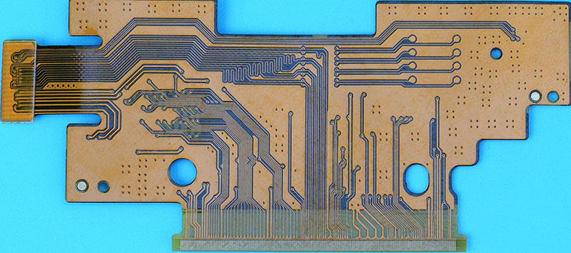
What Is Flex PCB Assembly?
Flex PCB assembly enables modern medical electronics to achieve levels of compactness, reliability, and functionality that rigid boards alone cannot support. Flexible circuits use polyimide substrates that bend, twist, or fold without breaking electrical continuity—making them ideal for devices implanted in the human body or worn close to the skin.
Flex PCB assembly requires specialized materials, equipment, and soldering control:
Components are mounted onto thin polyimide substrates rather than rigid FR4.
Circuits can fold into 3D structures to maximize internal space.
Carriers and stiffeners are used during assembly to prevent stretching and distortion.
Reflow soldering profiles are tuned for thin, heat-sensitive materials.
The design supports repeated flexing without cracking copper traces or weakening solder joints.
In medical applications, Flex PCB assembly enables ultra-lightweight designs for tools such as insulin pumps, pacemakers, imaging modules, hearing aids, surgical instruments, and continuous monitoring devices.
Flex PCB technology has become the backbone of miniaturized medical electronics, where every millimeter matters and long-term reliability is non-negotiable.
Table: Comparison of Flex PCB vs. Rigid PCB Characteristics
Characteristic
Flex PCB
Rigid PCB
Thickness
0.1-0.3 mm
1.6 mm+
Weight
Lightweight
Moderate to heavy
Bend Capability
100,000+ cycles
None
Space Efficiency
High
Moderate
Vibration Resistance
Excellent
Poor to moderate
Assembly Complexity
Integrated approach
Multi-step
How Does the Flex PCB Manufacturing Process Influence Final Assembly Quality?
The upstream fabrication process directly determines whether the final Flex assembly will survive medical use. Quality is affected by substrate chemistry, copper type, etching precision, and final surface finishing.
Key factors during manufacturing:
Material purity Medical-grade polyimide must withstand heat, chemical exposure, and repeated sterilization cycles without degrading.
Copper selection Rolled annealed (RA) copper is preferred because its grain structure resists cracking during dynamic bending better than electro-deposited (ED) copper.
Dimensional accuracy Tight etching control produces consistent trace width and thickness—critical for devices with high-frequency or low-noise requirements (ultrasound, ECG modules, imaging sensors).
Laser via formation Precision drilling ensures microvias maintain conductivity and structural strength throughout thousands of bending cycles.
Surface finish quality ENIG (Electroless Nickel Immersion Gold) or soft gold finishes provide stable solderability and better corrosion resistance under medical conditions.
Assembly quality is only as good as the fabrication process that precedes it. Any manufacturing defect is magnified when the device is used in a hospital, operating room, or implanted inside the human body.
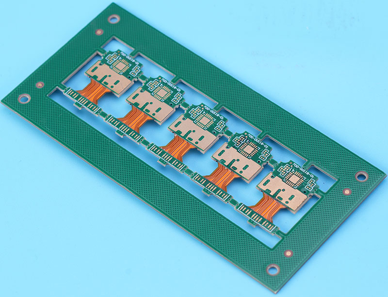
Why Do Engineers Choose Rigid Flex PCB Assembly for Medical Applications?
Rigid-flex PCBs integrate rigid sections for high-density component mounting with flexible interconnects that navigate compact medical housings. This hybrid architecture delivers exceptional electrical, mechanical, and spatial advantages.
Why engineers select rigid-flex for medical devices:
Eliminates connectors and cables Every connector removed equates to one less potential failure point—critical for life-supporting equipment.
Superior electrical performance Continuous copper paths ensure clean signals for medical imaging, sensing, and telemetry systems.
True 3D routing Allows electronics to wrap around curves or fit into cylindrical or irregular implants.
High durability Rigid-flex structures tolerate movement, vibration, and handling during surgery or patient activity.
Long service life Especially important when devices remain implanted for years.
Medical devices such as neurostimulators, pacemakers, endoscopes, robotic surgical tools, handheld scanners, and portable ultrasound systems rely heavily on rigid-flex PCBs for their unmatched combination of stability and flexibility.
Table: Medical Applications Benefiting from Rigid-Flex PCB Assembly
What Are the Key Steps in a Standard Flex PCB Assembly Process From Start to Finish?
Flex PCB assembly requires a tighter process window compared with rigid PCB assembly due to material thinness, dimensional sensitivity, and bend requirements.
A typical medical Flex PCB assembly sequence includes:
1. Pre-Bake and Moisture Removal
Polyimide absorbs moisture; if left untreated, it causes delamination during reflow.
Baking stabilizes the material and prevents blistering.
2. Solder Paste Application
Custom stencils and backing carriers ensure accurate printing.
Prevents deformation of the flexible substrate during paste deposition.
3. Component Placement
Pick-and-place machines are calibrated for extremely thin boards.
Carriers prevent bending under vacuum nozzles and mechanical pressure.
4. Reflow Soldering
Uses gentle thermal ramp-up to protect the flexible substrate.
Nitrogen atmosphere improves solder quality and reduces oxidation.
Multiple zones allow precise temperature control.
5. Inspection
AOI checks solder joints and placement accuracy.
X-ray identifies BGA voids and hidden solder issues.
What Factors Shape the Overall Flex PCB Assembly Price and How Are Quotes Calculated?
Medical Flex PCB pricing reflects the complexity and reliability demands of life-critical electronics.
Main Cost Drivers:
1. Material Selection
Polyimide grade
RA copper vs. ED copper
Conformal coatings and sterilization-resistant adhesives
2. Design Complexity
Layer count
Trace/space tolerance
Microvia density
Rigid-flex transition structure
3. Testing Requirements
AOI, X-ray, flying probe
Environmental stress tests
Biocompatibility documentation
4. Volume & NRE
Tooling, stencils, fixtures
Engineering development and validation cost
By understanding these cost drivers, medical companies can design smarter, reduce wasted expense, and maintain required levels of reliability.
Table: Cost Factors in Medical Flex PCB Assembly
Cost Factor
Impact Level
Optimization Strategy
Material Selection
High
Use suitable alternatives; avoid over-spec materials
Layer Count
High
Reduce layers; consider HDI to simplify stackups
Board Size
Medium
Improve panel utilization
Tolerances
High
Specify practical tolerances only
Surface Finish
Medium
Choose finish based on real reliability needs
Testing Requirements
Medium–High
Test critical areas; combine efficient inspection methods
Documentation
Medium
Keep documentation to essential requirements
Why Choose EBest Circuit (Best Technology) for Best Rigid-Flex PCB Assembly Services for Medical Devices?
BEST Technology provides medical OEMs with fully engineered Flex and rigid-flex PCB assembly solutions built for long-term, life-critical reliability.
What makes BEST Technology a strong partner:
Decades of expertise in Flex and rigid-flex manufacturing.
Medical-grade compliance, including ISO 13485-aligned processes.
Engineering support for stackup, bend radius, materials, and DFM/DFA optimization.
Advanced inspection using AOI, X-ray, flying probe, and reliability testing.
Stable production scalability from prototypes to large volumes.
Full traceability and detailed documentation for medical regulatory needs.
BEST Technology helps medical brands deliver safe, durable, and efficient devices built on precision-engineered Flex PCB and rigid-flex technology.
In a nutshell, flex PCB assembly enables the development of advanced medical devices through its unique combination of reliability, miniaturization, and dynamic functionality. As medical technology continues advancing toward less invasive procedures and more portable equipment, flex circuit technology will play an increasingly critical role in enabling these innovations. Understanding the principles outlined in this guide empowers medical device engineers to make informed decisions that balance performance, reliability, and manufacturability throughout the product development lifecycle .
At BEST Technology, we specialize in translating these principles into reliable, production-ready medical devices through our comprehensive rigid-flex PCB assembly services. Our medical industry expertise, combined with state-of-the-art manufacturing capabilities, ensures your devices meet the rigorous standards demanded by healthcare applications. Pls feel free to contact us at sales@bestpcbs.com to discuss how our flex PCB assembly solutions can enhance your medical device projects.