pcb
Home > Blog

Posts Tagged ‘MCPCB prototype’

MCPCB Design, MCPCB Prototype, MCPCB Supplier
Monday, July 28th, 2025

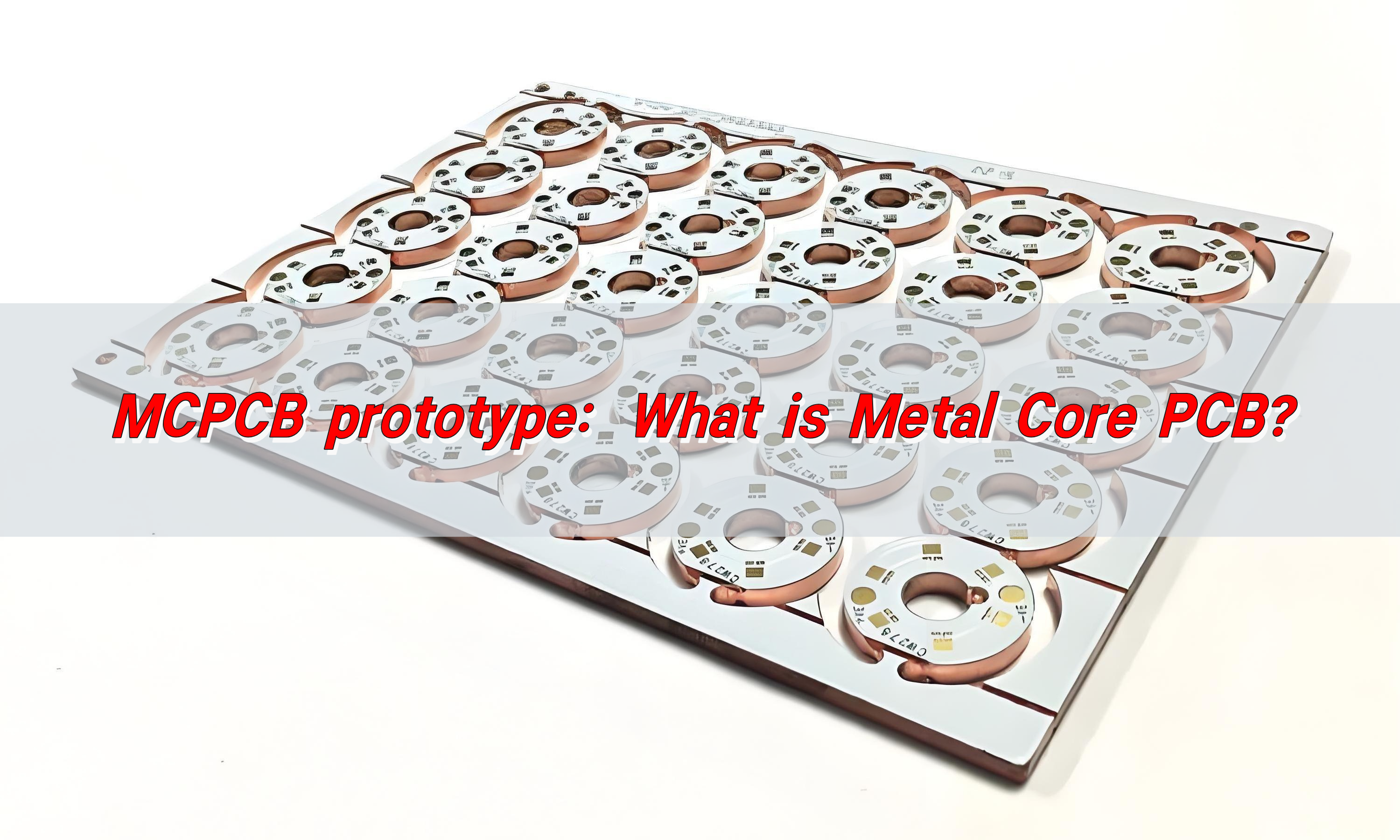
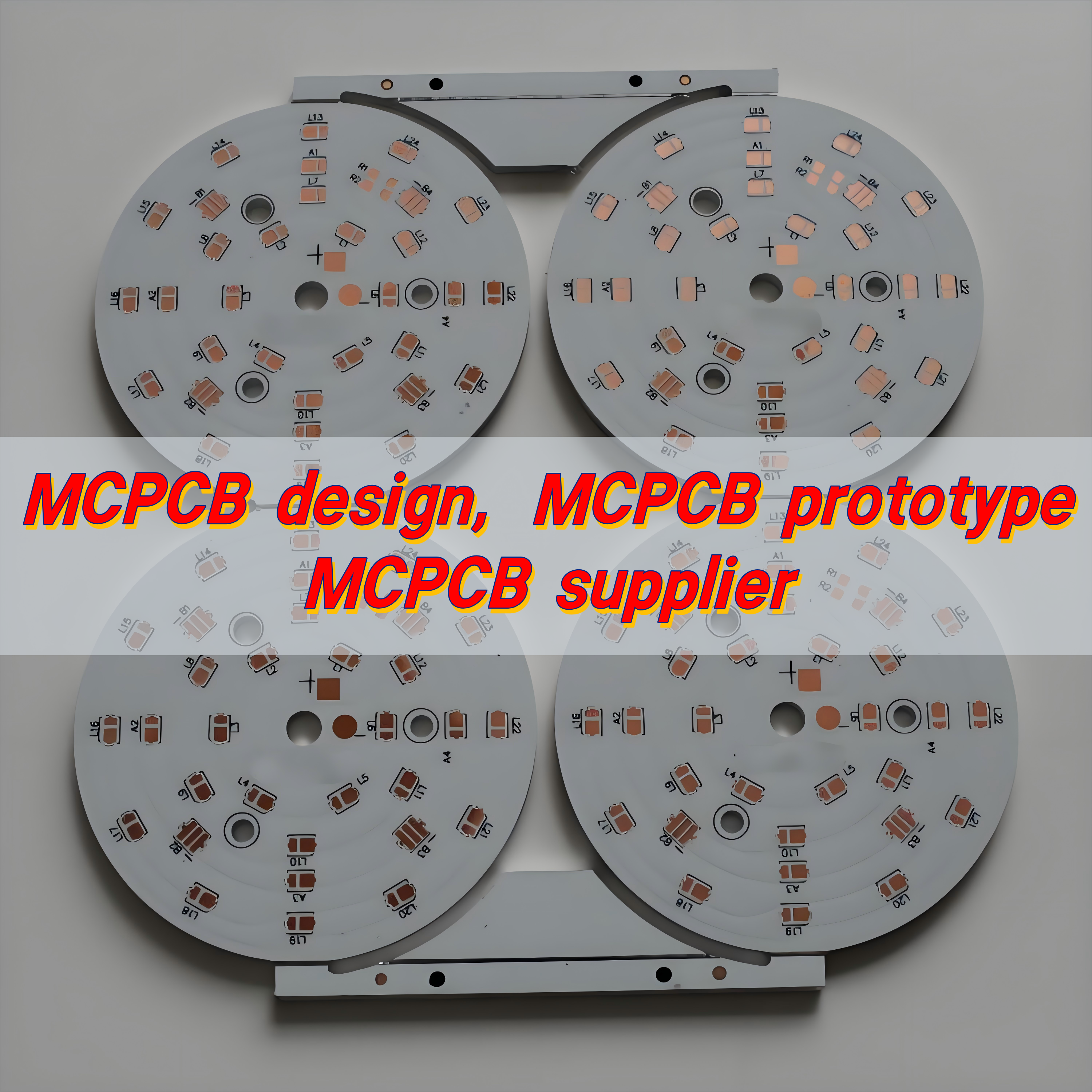
What is MCPCB design?

MCPCB stands for Metal Core Printed Circuit Board. Unlike regular PCBs made with fiberglass, MCPCBs use a metal base—usually aluminum or copper—as their core layer. This helps carry heat away from components. In MCPCB design, attention should be paid not only to the electrical layout but also to the thermal flow and mechanical strength.

MCPCB Design, MCPCB Prototype, MCPCB Supplier

MCPCBs are ideal for LED lights, power supplies, automotive electronics, and high-temperature environments. Their main job is to conduct heat away from sensitive components while maintaining solid electrical performance.

So, what is MCPCB design? It’s the process of creating a printed circuit board with a metal core that balances power, heat, and cost—all in one compact board.

What is the MCPCB definition?

By definition, an MCPCB is a circuit board that contains:

  • A copper circuit layer for electrical conductivity.
  • A dielectric layer for insulation.
  • A metal base for heat dissipation (aluminum or copper).

The “MC” in MCPCB represents the metal core, which is what sets it apart from standard PCBs. This unique core allows the board to perform better in thermal management, giving it a clear edge in high-power applications.

In simpler terms, MCPCB = Metal + Circuit + Insulation, all working together.

How does MCPCB design affect cost and performance?

When done right, MCPCB design helps reduce overheating, extends component life, and cuts maintenance costs. But if the thermal path isn’t optimized or trace routing isn’t clean, you might face issues like:

  • Poor heat dissipation
  • Solder joint failure
  • Component damage
  • Lower LED brightness

All of this can push your costs up. A smart design, on the other hand, balances performance and cost from the beginning. For example:

MCPCB Design, MCPCB Prototype, MCPCB Supplier
  • Using aluminum instead of copper reduces cost without hurting performance for most LED boards.
  • Selecting the right dielectric material keeps the board thin while ensuring heat is controlled.
  • Clear trace paths help maintain signal integrity and reduce EMI.

What’s the difference between MCPCB and standard PCBs?

Standard PCBs use FR4 (a fiberglass-reinforced epoxy) as the core. They work well in normal-temperature environments. But as power or current increases, they heat up quickly. And they don’t cool down fast.

MCPCBs, on the other hand, are built for heat. They use a metal core (usually aluminum) instead of FR4. This change gives them superior thermal conductivity, making them ideal for high-power devices.

Let’s put it in simple terms:

  • Standard PCB = Best for low-heat, general electronics.
  • MCPCB = Best for high-heat, high-performance applications.

This key difference changes how you approach layout, stack-up, and assembly. That’s why MCPCB design must be treated differently from standard boards.

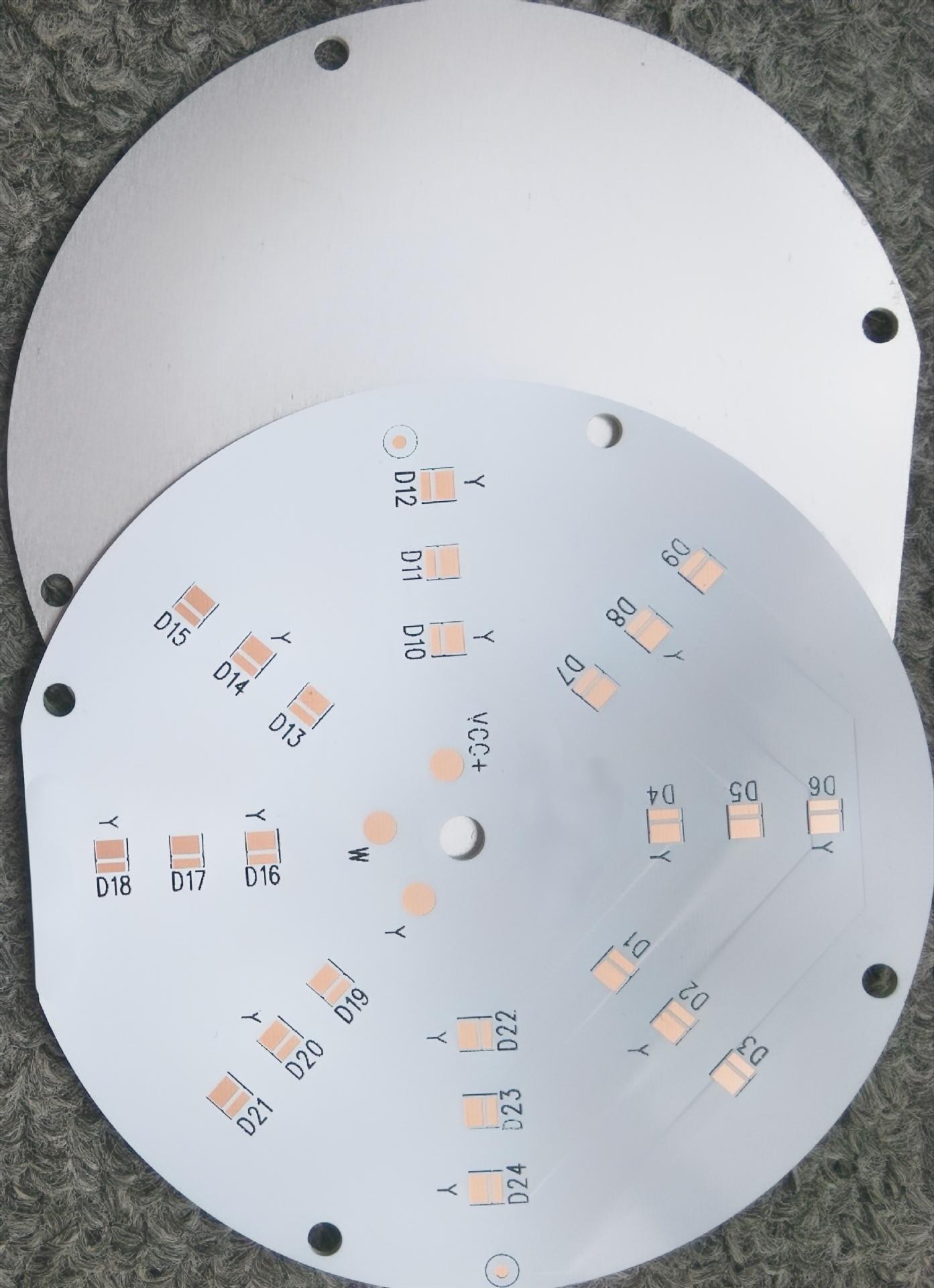
Why use MCPCB prototype for testing?

Testing MCPCB prototypes before committing to mass production can save you a ton of money and weeks of lost time.

A prototype helps you:

  • Test thermal behavior in real conditions
  • Check for design flaws or unexpected hot spots
  • Ensure your LED PCB maintains brightness under load
  • Evaluate material quality from your chosen MCPCB supplier

Also, prototyping speeds up development. You get real data fast. This keeps your timeline tight and your product launch on track.

What are key MCPCB design guidelines?

Designing a metal core PCB takes a different mindset. Follow these essential MCPCB design guidelines:

  • Know your heat source: Place hot components close to vias or thermal pads.
  • Use wide copper traces: Helps current flow without resistance.
  • Choose the right metal base: Aluminum for cost-efficiency; copper for higher thermal performance.
  • Mind your dielectric layer: Thin layers cool better, but must still insulate properly.
  • Leave room for expansion: Heat causes expansion. Mechanical stress can break solder joints.
MCPCB Design, MCPCB Prototype, MCPCB Supplier

The more you follow these core rules, the better your board will perform and the longer its actual service life will be.

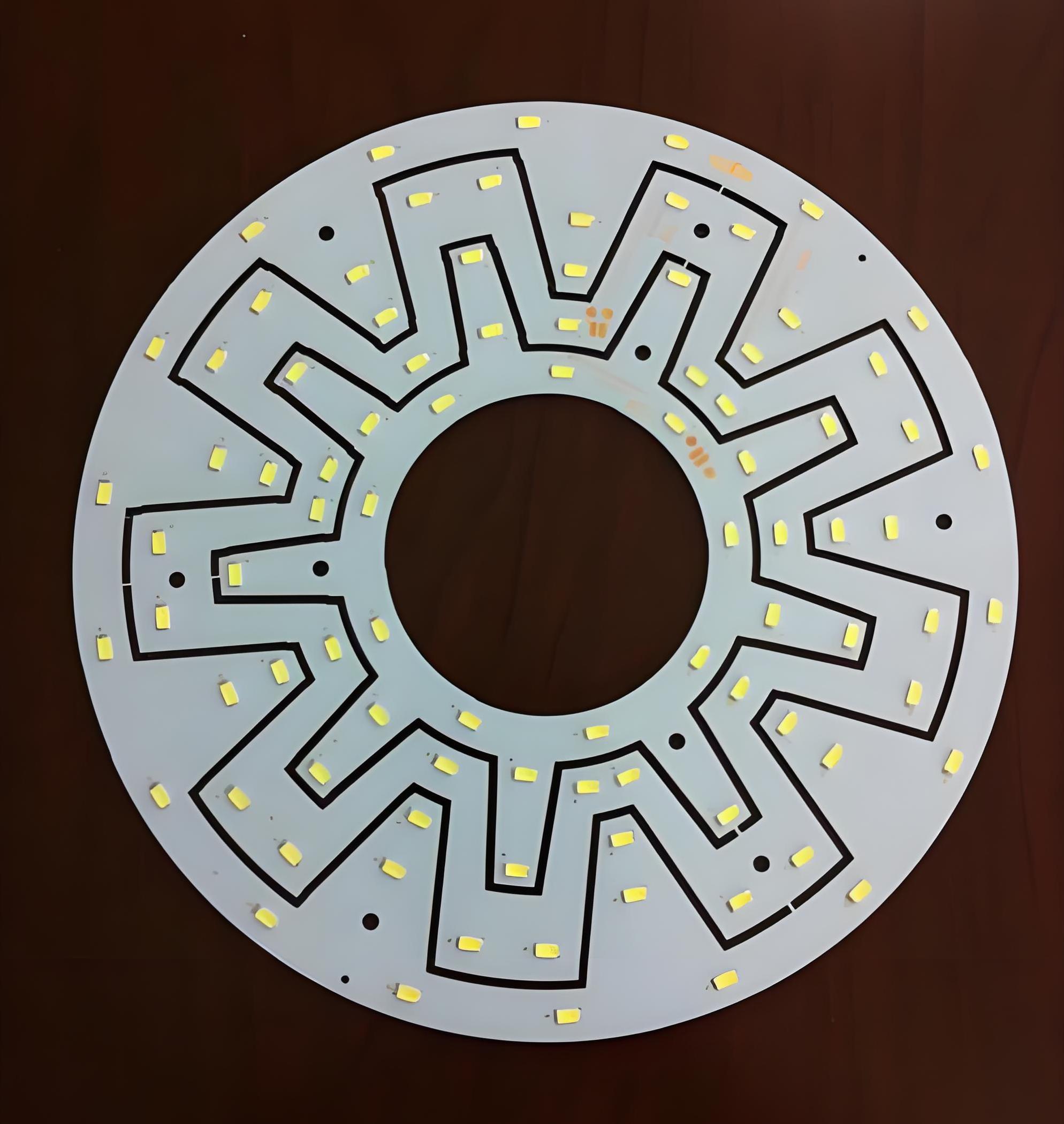
Why is MCPCB design critical for LED PCB?

LEDs are sensitive. As their temperature increases, their brightness drops. At high temps, their lifespan can also shrink dramatically. That’s why LED lighting depends on MCPCBs to manage heat efficiently.

With a properly designed LED PCB, you get:

  • Brighter output with less energy
  • Longer LED life
  • Stable color over time
  • No flicker or degradation

Poor thermal design can degrade LED performance, even if the rest of the circuit is very robust. MCPCB design can protect LED performance.

If you’re in automotive, medical, or commercial lighting, this can make or break product quality.

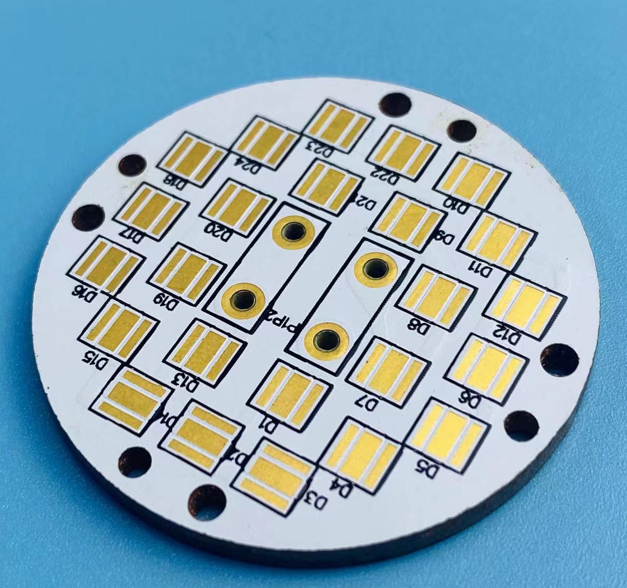
How is aluminum PCB better for LEDs?

When comparing aluminum PCBs to standard fiberglass ones for LEDs, aluminum wins by a landslide. Here’s why:

  • Aluminum conducts heat better: It draws heat away from the LED’s base.
  • It’s lightweight and strong: Perfect for compact fixtures.
  • It reduces component failure: Lower heat = longer life.
  • It’s cost-effective: Compared to copper, aluminum gives great performance without high cost.

Aluminum MCPCBs have become the gold standard for LED applications. They offer the right balance of thermal conductivity, cost, and mechanical strength.

How to choose the right MCPCB supplier?

With nearly two decades of experience, Best Technology offers consistent quality, fast delivery, and responsive support.

MCPCB Design, MCPCB Prototype, MCPCB Supplier

When choosing a supplier, look for these essentials:

  • In-house MCPCB design services: At Best Technology, our expert engineering team collaborates closely with you to streamline development and eliminate communication delays.
  • Material transparency: We use only verified raw materials, including high-purity aluminum and top-tier dielectric insulation, ensuring long-lasting performance.
  • Certifications and experience: Best Technology is ISO9001:2015 certified, RoHS/REACH compliant, and trusted by global customers across automotive, medical, industrial, and lighting sectors.
  • Quick technical support: Our 48-hour technical response commitment ensures that your questions are answered when you need them most.
  • Providing customized solutions: from unique thermal stack-ups to integrated LED designs

Conclusion:

MCPCB design plays a vital role in ensuring performance, reliability, and thermal control in modern electronics—especially in LED PCBs and high-power applications.

And selecting a trusted MCPCB supplier—like Best Technology—ensures expert support, fast prototyping, and consistent quality from concept to production.

Need help with MCPCB design, prototyping, or sourcing? Contact us at sales@bestpcbs.com to get started.

MCPCB prototype: What is Metal Core PCB?
Friday, February 21st, 2025

MCPCB prototype refers to Metal Core PCB. It consists of a metal substrate (such as aluminum or copper), an insulation layer, and a copper foil circuit layer. It has good heat dissipation performance and mechanical strength, and is suitable for high-power, high-heat dissipation demand application scenarios such as LED lighting, automotive electronics, and power management.

MCPCB prototype: What is Metal Core PCB?

What is mcpcb?

MCPCB stands for Metal Core Printed Circuit Board, a specialized type of PCB that includes a metal substrate instead of the traditional fiberglass (FR4) material. The purpose of the metal core is to improve heat transfer, ensuring that components operate within safe temperature limits.

In electronic devices that generate significant heat, such as high-power LEDs and automotive circuits, standard PCBs struggle with heat dissipation, leading to performance degradation and component failure. MCPCBs solve this issue by quickly transferring heat away from critical areas, maintaining optimal performance and extending product lifespan.

How to design mcpcb?

Designing an MCPCB requires careful consideration of heat dissipation, electrical performance, and mechanical stability.

Engineers begin by selecting the appropriate metal base, with aluminum being the most common due to its balance of cost, thermal conductivity, and lightweight properties. Copper offers even better conductivity but is more expensive, while steel provides mechanical strength but lower heat dissipation efficiency.

The layout design of an MCPCB involves optimizing the placement of components to ensure even heat distribution. High-power components, such as LEDs or power transistors, are positioned strategically to minimize thermal buildup. Thermal vias may be incorporated to enhance heat transfer through the board.

The dielectric layer, which sits between the metal core and the copper circuit layer, must have high thermal conductivity while maintaining electrical insulation. Surface finishes, such as ENIG (Electroless Nickel Immersion Gold) or HASL (Hot Air Solder Leveling), are applied to protect the circuit layer and ensure high solderability.

What are the materials in Mcpcb?

The construction of an MCPCB consists of multiple layers, each serving a specific function. The metal base is typically made from aluminum, copper, or steel, providing a solid foundation for heat dissipation.

MCPCB prototype: What is Metal Core PCB?

Above the metal base lies the dielectric layer, which is a thermally conductive but electrically insulating material that allows heat to pass through while preventing electrical shorts.

The topmost layer is the copper circuit layer, where electrical components are placed. The thickness of this copper layer varies depending on the current-carrying requirements of the circuit. A protective solder mask is applied over the copper traces to prevent oxidation and unintentional short circuits.

Additionally, a silkscreen layer may be added for labeling and component identification. The choice of these materials significantly impacts the board’s thermal conductivity, durability, and overall performance.

What is the thermal conductivity of Mcpcb?

Thermal conductivity is a key property of MCPCBs, as it determines how effectively the board can transfer heat away from components. The dielectric layer, in particular, plays a crucial role in thermal performance. Standard FR4 PCBs have a thermal conductivity of around 0.3–0.5 W/mĀ·K, whereas MCPCBs typically range from 1 to 8 W/mĀ·K, depending on the materials used.

Aluminum-based MCPCBs generally have a thermal conductivity between 1 and 3 W/mĀ·K, while copper-based MCPCBs can reach up to 8 W/mĀ·K, making them ideal for applications requiring maximum heat dissipation.

What is the function of Mcpcb?

MCPCBs serve a crucial function in thermal management and electrical performance. Their primary role is to dissipate heat efficiently, preventing hotspots and ensuring that components operate at safe temperatures. This thermal regulation improves the longevity and reliability of electronic devices, reducing the risk of overheating and failure.

In addition to heat dissipation, MCPCBs provide mechanical strength and stability, making them suitable for rugged environments where vibrations and mechanical stress are concerns.

MCPCB prototype: What is Metal Core PCB?

Their ability to handle high power levels makes them ideal for LED lighting, power amplifiers, industrial controls, and automotive electronics.

Unlike traditional PCBs, which struggle with heat-related performance issues, MCPCBs offer a practical solution for high-power applications.

What is the difference between FR4 and Mcpcb?

FR4 and MCPCB differ significantly in terms of thermal performance, material composition, and applications. FR4 PCBs are made from a fiberglass-reinforced epoxy laminate, which provides good electrical insulation but poor thermal conductivity.

However, in high-power electronics, FR4 PCBs struggle to dissipate heat efficiently, leading to performance issues and potential component damage.

MCPCBs, on the other hand, incorporate a metal base that dramatically improves thermal performance. The metal core acts as a heat sink, drawing heat away from components and distributing it across the board. This feature makes MCPCBs ideal for applications where thermal management is critical, such as LED lighting, automotive electronics, and power circuits.

While FR4 PCBs remain popular for general electronics, MCPCBs are the preferred choice for high-power, heat-sensitive applications.

What is the difference between PCB and Mcpcb?

The fundamental difference between standard PCBs and MCPCBs lies in their construction and heat dissipation capabilities. Traditional PCBs use an insulating fiberglass material as their core, whereas MCPCBs use a thermally conductive metal core.

MCPCB prototype: What is Metal Core PCB?

MCPCBs are especially beneficial for industries requiring robust thermal management solutions. In high-brightness LED applications, for example, excessive heat can degrade LED performance and lifespan. MCPCBs prevent this by dissipating heat quickly, ensuring consistent light output and prolonged durability.

Additionally, in power electronics, MCPCBs enable efficient energy conversion and prevent thermal stress, leading to improved performance and reduced failure rates.

What is a prototype circuit board?

A prototype circuit board is an early-stage version of a PCB used for testing and validation before full-scale production. This process helps reduce production costs and ensures that the final product meets performance requirements.

MCPCB prototypes are particularly valuable in industries that demand high power efficiency and superior thermal management. By testing a prototype, engineers can assess the board’s heat dissipation capabilities, optimize component placement, and make necessary modifications before large-scale manufacturing.

What are the different types of prototype boards?

Prototype boards come in various types, each tailored to specific applications.

Standard FR4 prototype boards are widely used for general circuit testing, offering flexibility and cost-effectiveness.

Flexible PCBs and rigid-flex PCBs are used in compact and wearable devices where space constraints and flexibility are critical.

High-frequency PCBs cater to communication systems requiring stable signal transmission.

MCPCB prototypes stand out for their ability to handle high-power applications with efficient heat dissipation. These prototypes are essential for industries such as automotive, aerospace, and industrial power systems, where thermal management is a top priority.

Conclusion:

MCPCBs provide a superior solution for electronic applications requiring effective heat dissipation and durability. Their metal core design enables efficient thermal management, making them the preferred choice for LED lighting, power electronics, and industrial control systems.

For high-quality MCPCB prototyping and manufacturing, Best Technology provides advanced solutions tailored to your specific requirements. Contact us at sales@bestpcbs.com for expert guidance and custom MCPCB solutions.