

Are you tired of EV inverter MCPCB issues like overheating, signal interference, and poor durability ruining your EV inverter performance? Our EV Inverter MCPCB delivers industry-leading thermal conductivity (up to 8.0 W/m.K), IATF 16949 & AEC-Q100 certification, and reliable performance in extreme automotive environments (-40°C to +150°C), solving these pain points and making it the top choice for high-performance electric vehicle applications.
Why Choose EBest for Your EV Inverter MCPCB Needs?
Choosing EBest for your EV inverter MCPCB means partnering with a provider that delivers data-backed value and solves your project pain points.
- Industry-Leading Quality: Our EV Inverter MCPCB has a 99.8% pass rate (vs. industry 95%), with 1000+ thermal cycles, zero delamination, and insulation resistance ≥100MΩ, ensuring safe, reliable EV inverter operation.
- Fast Turnaround: EV Inverter MCPCB prototypes in 3-5 days, mass production in 7-12 days, 30% faster than industry average, cutting launch time by up to 4 weeks.
- Cost-Efficiency: 15-20% lower production costs vs. competitors, with no compromise on EV Inverter MCPCB performance or quality, boosting your project profitability.
- 24/7 Expert Support: Our team reduces design errors by 25%, improves yield to 99.5%, and provides DFM guidance to optimize yourEV Inverter MCPCB design.
- Stable Supply Chain: 99.9% on-time delivery (vs. 17.5% industry supply gap), global material partners, and full traceability to avoid project delays.
- Premium Tailored Specs: Our EV Inverter MCPCB features 8.0 W/m.K thermal conductivity, 1.0-5.0mm copper core, 250A capacity, and AEC-Q100 compliance for extreme under-hood use.
What Certifications Do Our EV Inverter MCPCBs Have?
Our EV inverter MCPCB holds industry-leading certifications, each designed to guarantee performance, reliability, and compliance with automotive standards. Below are our key certifications:
- IATF 16949 Certification: Ensures full control of the production process, from material selection to final inspection, eliminating quality hazards and meeting global automotive manufacturing standards. It includes APQP, PPAP, and FMEA processes to prevent defects before production.
- UL Certification: Confirms electrical safety and fire resistance, ensuring our EV Inverter MCPCB operates safely in high-voltage EV systems without short circuits or thermal runaway.
- RoHS & REACH Certification: Ensures our EV Inverter MCPCB is free of harmful substances, complying with global environmental regulations for automotive electronics.
Common EV Inverter MCPCB Pain Points & How EBest Solve Them
Many users struggle with EV inverter MCPCB issues that disrupt performance, increase costs, and delay projects. We address these common pain points with targeted solutions, ensuring your inverter systems run smoothly.
Pain Point 1: Thermal Buildup in High-Current Operations
Solution: Our copper core EV Inverter MCPCB has a thermal conductivity of up to 8.0 W/m.K, 20x higher than traditional FR4 PCBs. It efficiently dissipates heat from IGBTs and power modules, preventing overheating and component failure.
Pain Point 2: Delamination and Poor Mechanical Strength
Solution: We use advanced vacuum lamination technology and high-quality dielectric materials to ensure strong bonding between layers. Our EV Inverter MCPCB withstands 1000+ thermal cycles and vibration testing (per ISO 16750-3) without delamination.
Pain Point 3: Signal Interference Affecting Inverter Efficiency
Solution: Our design optimizes power and signal zone separation, with thick copper traces (2-6oz) and grounded planes to minimize parasitic inductance and signal distortion, improving inverter efficiency by up to 5%.
Pain Point 4: Unreliable Supply and Long Lead Time
Solution: We maintain a stable supply chain with global material partners and flexible production capacity. Our fast turnaround ensures you get your EV Inverter MCPCB prototypes and mass orders on time, every time.
For all your EV Inverter MCPCB needs, EBest is your trusted partner, we solve your pain points so you can focus on building high-performance EV systems. Contact us today to discuss your project.
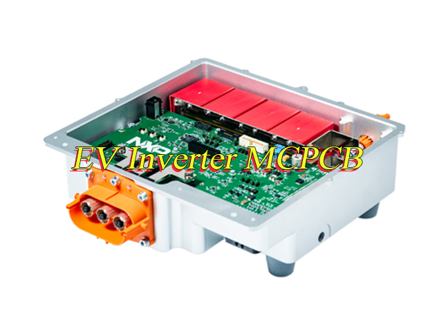
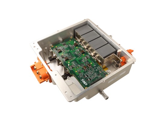
What Is an EV Inverter MCPCB & Why It’s Essential for EV Inverter Performance?
An EV inverter MCPCB (Electric Vehicle Inverter Metal Core Printed Circuit Board) is a specialized PCB with a copper or aluminum core, designed to handle high currents and dissipate heat in EV inverter systems. It is critical because EV inverters convert DC power from the battery to AC power for the motor, generating significant heat and requiring stable performance.
Without a high-quality EV Inverter MCPCB, inverters suffer from overheating, component failure, and reduced efficiency, leading to shorter EV range and higher maintenance costs. Our copper core solutions are engineered to address these challenges, making them essential for modern EVs.
How Does the Copper Core Improve EV Inverter MCPCBs Performance?
The copper core is the key to superior EV inverter MCPCB performance, offering three critical benefits that traditional PCBs cannot match.
First, copper has excellent thermal conductivity (up to 401 W/m.K), allowing the EV Inverter MCPCB to quickly dissipate heat from high-power components like IGBTs and SiC MOSFETs. This prevents overheating and extends component lifespan.
Second, copper core provides higher current-carrying capacity, our EV Inverter MCPCB handles up to 250A, supporting high-power EV inverters (100-400 kW) without voltage drops or line overheating.
Third, copper core enhances mechanical strength, making the EV Inverter MCPCB resistant to vibration and shock, critical for automotive under-hood environments.
What Are the Design Considerations for EV Inverter MCPCB?
Designing an EV inverter MCPCB requires careful attention to multiple key factors to ensure optimal performance, long-term reliability, and easy manufacturability. Below are the essential design considerations to follow.
- Thermal Design Optimization: Optimize the copper core thickness of your EV Inverter MCPCB between 1.0-5.0mm to enhance heat dissipation. Incorporate thermal vias and thermal pads to create efficient heat transfer paths. This effectively manages heat generated by high-current components like IGBTs and SiC MOSFETs. Large copper pours on the board also help distribute heat evenly and prevent hotspots.
- Current Capacity Planning: Use thick copper traces (2-6oz) to ensure your EV Inverter MCPCB can handle up to 250A of current without voltage drops or power loss. Shorten power loop paths as much as possible to reduce parasitic inductance. This inductance can cause voltage spikes and affect inverter efficiency.
- Signal Integrity Protection: Separate power and signal zones on the EV Inverter MCPCB by at least 10mm to avoid interference. Use grounded planes to shield sensitive circuits and minimize signal distortion. Keep sensitive signal traces short and away from high-current lines to maintain signal accuracy.
- Manufacturability Compliance: Follow DFM (Design for Manufacturability) guidelines to reduce production defects. Optimize line width, spacing, and hole size to improve production yield. Ensure the EV Inverter MCPCB design aligns with standard manufacturing tolerances to avoid assembly issues.
- High Voltage Clearance: Maintain adequate clearance and creepage distances per IPC-2221 and ISO 6469 standards to prevent arcing and insulation breakdown. This is critical for EV Inverter MCPCB operating in high-voltage EV systems. It is especially important between high-voltage and low-voltage regions to avoid safety risks and system failure.
- Stack-Up Design: Use a symmetric stack-up for your EV Inverter MCPCB to reduce warpage during reflow soldering. Incorporate inner planes as ground or thermal planes to enhance stability and heat dissipation. Choose high TG prepregs to withstand elevated operating temperatures in automotive environments.
- Component Placement: Place high-power components like IGBTs and MOSFETs near the board edge or heat sinks to improve heat dissipation. Position high-frequency ceramic capacitors close to switching transistor VCC/GND pins (less than 5mm) to suppress transient current noise. Keep current sampling resistors close to the components they monitor for accurate readings.
- Grounding Strategy: Implement separate power ground (PGND) and signal ground (SGND) on the EV Inverter MCPCB. Connect them at a single point near the input capacitor. Maintain a complete ground plane to ensure low impedance return paths and reduce noise.
- EMI Mitigation: Minimize electromagnetic interference by keeping drive signal traces short and straight (less than 30mm) and away from high-frequency nodes. Use copper foil shielding rings around sensitive components to reduce noise coupling. Optimize the layout of transformers and inductors to minimize magnetic leakage.
- Mechanical Stability: Ensure the EV Inverter MCPCB has sufficient mechanical strength to withstand automotive vibration and shock per ISO 16750-3 standards. Choose durable materials and avoid large unsupported areas that could lead to warping or damage.
How Does EV Inverter MCPCB Compare to Traditional FR4 PCBs?
Traditional FR4 PCBs are unsuitable for EV inverters due to poor thermal performance and low current capacity. Below is a detailed comparison with our EV Inverter MCPCB:
| Performance Factor | EV Inverter MCPCB (Copper Core) | Traditional FR4 PCB |
| Thermal Conductivity | Up to 8.0 W/m.K (dielectric layer); 401 W/m.K (copper core) | ~0.3 W/m.K |
| Current Capacity | Up to 250A | Max 50A (limited by heat buildup) |
| Operating Temperature Range | -40°C to +150°C (AEC-Q100 Grade 0) | -20°C to +105°C |
| Mechanical Strength | High (resistant to vibration and shock) | Low (prone to warping and damage) |
| Suitability for EV Inverters | Ideal (handles high current and heat) | Unsuitable (high failure rate) |
How to Test the Reliability of EV Inverter MCPCBs?
Reliability testing for EV inverter MCPCB ensures compliance with automotive standards and consistent performance in harsh under-hood environments. Below are six critical, actionable tests we use to validate every EV Inverter MCPCB, with specific parameters to help you assess quality.
- Thermal Cycle Testing: Run 1000 or more cycles between -40°C and +150°C to verify the EV Inverter MCPCB resists delamination and material degradation. This test simulates extreme temperature fluctuations in automotive operation to ensure long-term thermal reliability.
- High-Temperature Storage: Store the EV Inverter MCPCB at +150°C for 1000 hours to confirm material stability. This test prevents thermal degradation that could lead to component failure or reduced conductivity in high-heat inverter environments.
- Vibration Testing: Conduct testing per ISO 16750-3 standards, covering 10Hz to 2kHz, to simulate road vibration. This ensures the EV Inverter MCPCB maintains structural integrity and solder joint stability during vehicle operation.
- Insulation Resistance Testing: Verify electrical insulation between EV Inverter MCPCB layers to prevent short circuits in high-voltage EV systems. We use 500V DC testing to ensure insulation resistance of ≥100MΩ, meeting automotive safety standards.
- Thermal Shock Testing: Perform 100 cycles between -40°C and +125°C, with temperature transitions within 10 seconds as required by IATF 16949. This validates the EV Inverter MCPCB resists rapid temperature changes common in automotive use.
- AOI Inspection: Conduct 100% automated optical inspection to detect line defects, short circuits and component misalignment. This aligns with IPC-A-610 Class 3 standards for high-reliability electronics, ensuring zero manufacturing flaws in EV Inverter MCPCB.
What EV Inverter MCPCB Application Cases Do You Have?
We have successfully delivered EV inverter MCPCB solutions for multiple EV manufacturers, solving critical performance issues. Below is a real-world application case:
Case Study: 7.5kW SiC EV Inverter – A customer was struggling with overheating and low efficiency in their SiC-based EV inverter. Their existing PCB had thermal conductivity of 1.5 W/m.K, leading to IGBT temperatures exceeding 150°C and inverter efficiency of 92%.
We provided a copper core EV Inverter MCPCB with 8.0 W/m.K thermal conductivity and optimized power loop design. After implementation, IGBT temperatures dropped to 120°C, and inverter efficiency increased to 97.2%.
The customer also benefited from our fast prototype delivery (3 days) and mass production turnaround (10 days), allowing them to accelerate their product launch by 4 weeks.
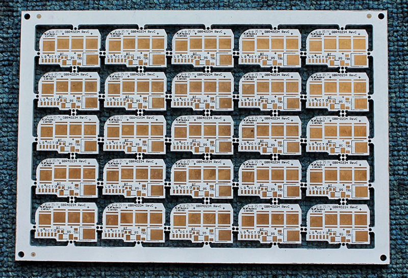
What Are the Common Sizes and Customization Options for EV Inverter MCPCBs?
Our EV inverter MCPCB is available in standard sizes and fully customizable to meet your specific inverter design requirements.
Standard Sizes: 100x100mm, 150x150mm, 200x200mm, 250x250mm (compatible with most small to medium EV inverters).
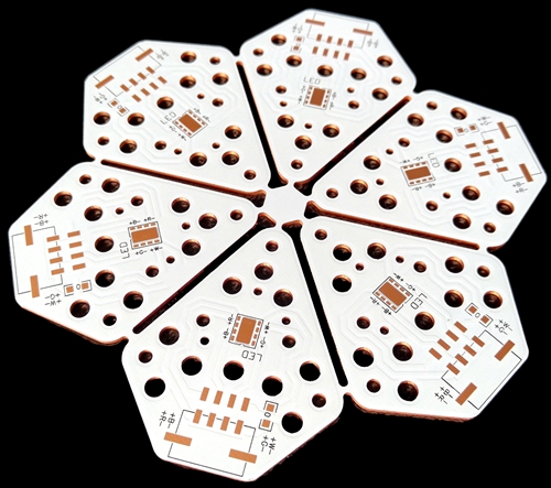
Customization Options: Copper core thickness (1.0-5.0mm), copper foil thickness (2-6oz), dielectric layer thickness (0.1-0.5mm), thermal conductivity (1.5-8.0 W/m.K), and custom shapes/sizes to fit your inverter enclosure.
We also offer custom surface finishes (ENIG, OSP, HASL) and thermal via designs to optimize heat dissipation and solderability for your specific components.
How to Select the Right EV Inverter MCPCB Manufacturer?
Selecting the right EV inverter MCPCB manufacturer is critical to ensuring product quality, on-time delivery, and technical support. Below are actionable, detailed factors to guide your selection, each focused on tangible value for your EV inverter projects.
- Verify Automotive-Grade Certifications: Prioritize manufacturers with IATF 16949 and AEC-Q100 certifications. These certifications ensure strict production process control, from material selection to final inspection, and validate that the EV Inverter MCPCB meets automotive reliability and safety standards. Certifications also include APQP, PPAP, and FMEA processes to prevent defects before production.
- Evaluate Technical Capabilities: Choose manufacturers with advanced production and testing equipment for EV Inverter MCPCB. Look for expertise in copper core lamination, precision CNC drilling, and thermal performance testing. Experience in automotive PCB production, especially for high-current, high-heat applications like EV inverters, is essential to avoid design and manufacturing flaws.
- Assess Delivery Speed and Flexibility: Prioritize manufacturers with fast turnaround times for both prototypes and mass production. Reliable EV Inverter MCPCB providers deliver prototypes in 3-5 days and mass orders in 7-12 days. Flexibility to accommodate design changes and rush orders also helps avoid project delays and keep your timeline on track.
- Check Support and DFM Capabilities: Select manufacturers that offer 24/7 technical support and DFM (Design for Manufacturability) guidance. Expert support helps optimize your EV Inverter MCPCB design, reduce errors, and improve production yield. Look for teams with experience in automotive PCB design to address thermal, signal integrity, and high-voltage challenges.
- Validate Supply Chain Stability: Ensure the manufacturer has a global network of trusted material partners for copper foil, dielectric materials, and other EV Inverter MCPCB components. Full production traceability (per IATF 16949) and a proven track record of 99%+ on-time delivery minimize supply chain risks and material shortages.
- Review Quality Control Processes: Look for manufacturers with strict quality control measures, including 100% AOI inspection, thermal cycle testing, and insulation resistance testing. A high pass rate (99.5%+) for EV Inverter MCPCB ensures consistent performance and reduces the risk of component failure in harsh automotive environments.
- Assess Customization Capabilities: Choose a manufacturer that offers tailored EV Inverter MCPCB solutions. Customization options should include copper core thickness (1.0-5.0mm), copper foil thickness (2-6oz), thermal conductivity, and custom shapes/sizes to fit your specific inverter design requirements.
- Check Customer Testimonials and Case Studies: Review real-world application cases and customer feedback to verify the manufacturer’s ability to deliver reliable EV Inverter MCPCB solutions. Look for case studies that demonstrate success in solving thermal, current, or reliability challenges similar to your project.
FAQs About EV Inverter Metal Core PCB
Q1: What is the maximum current an EV inverter metal core PCB can handle?
A1: Our EV Inverter MCPCB can handle up to 250A, making it suitable for high-power EV inverters (100-400 kW). The current capacity is determined by copper core thickness, trace width, and thermal design.
Q2: How long does it take to deliver EV Inverter MCPCB prototypes?
A2: We deliver EV Inverter MCPCB prototypes in 3-5 days, with mass production delivery in 7-12 days. This fast turnaround helps you accelerate your design validation and product launch.
Q3: Does EV Inverter MCPCBs require special manufacturing processes?
A3: Yes, EV Inverter MCPCB requires advanced vacuum lamination, precision CNC drilling, and strict SPC process control to ensure layer bonding and thermal performance. We have specialized equipment to handle these processes.
Q4: Can EV Inverter MCPCBs be used in extreme automotive environments?
A4: Yes, our EV Inverter MCPCB is AEC-Q100 Grade 0 certified, operating reliably in temperatures from -40°C to +150°C. It also withstands vibration, shock, and high humidity, making it ideal for under-hood EV applications.
Q5: How do I optimize my EV Inverter MCPCBs design for better thermal performance?
A5: To optimize thermal performance, increase copper core thickness (1.5-5.0mm), add thermal vias (Φ0.3mm array), and place high-power components near the board edge for better heat dissipation. Our DFM team can provide personalized guidance.