

Ethernet connector PCB plays a critical role in enabling reliable network communication between electronic devices, ensuring stable data transmission in industrial, medical, and automation systems. This blog explains the design principles, prototype considerations, assembly challenges, and practical engineering guidelines for developing high-reliability Ethernet connector PCBs.
EBest Circuit (Best Technology) is a professional manufacturer specializing in ethernet connector PCB fabrication and PCBA services. With 20 years of experience serving more than 10,000 engineers and 1,800 global customers, our team provides full-process technical support. We offer free DFM analysis, custom ethernet connector PCB design, connector ethernet PCB manufacturing, components sourcing, and PCBA assembly under one roof, supported by certified quality systems including ISO9001, ISO13485, IATF16949, and AS9100D. Our digital MES production system enables fast traceability and stable quality, while flexible production supports prototypes and small-to-medium volume orders. If you are looking for a reliable ethernet connector PCB manufacturer, feel free to contact EBest for engineering support and production inquiries at sales@bestpcbs.com.
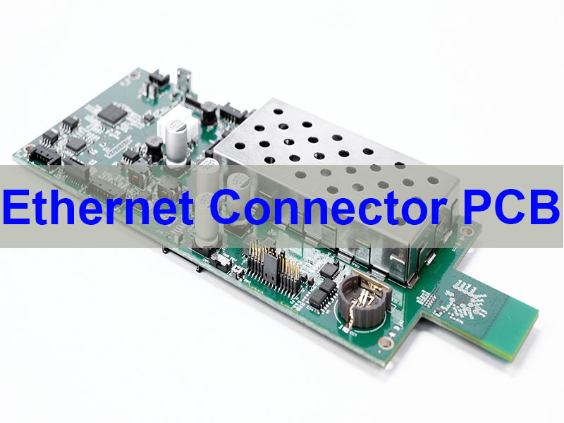
What Is an Ethernet Connector PCB?
An ethernet connector pcb is a printed circuit board that integrates Ethernet connectors directly onto the board to provide network communication interfaces.
These connectors enable devices to transmit data through Ethernet cables while maintaining electrical integrity and mechanical stability.
Common types include:
- RJ45 PCB connectors
- M12 Ethernet connectors
- Waterproof Ethernet connectors
- Industrial Ethernet connectors
Such PCBs are widely used in networking equipment and embedded systems.
What Are the Most Common Ethernet PCB Connectors?
Several connector types are commonly used in Ethernet PCB designs.
| Connector Type | Application | Protection Level |
|---|---|---|
| RJ45 PCB Connector | Standard networking equipment | Standard |
| M12 Ethernet Connector PCB | Industrial automation | IP67 |
| Waterproof Ethernet PCB Connector | Outdoor communication systems | IP67/IP68 |
| PCB Mount Ethernet Connector | Embedded devices | Standard |
Selecting the correct connector type depends on environmental requirements.
What Is the Difference Between RJ45 and M12 Ethernet PCB Connectors?
| Feature | RJ45 Connector | M12 Connector |
|---|---|---|
| Environment | Indoor networking | Industrial environments |
| Protection | Standard | IP67 waterproof |
| Locking mechanism | Clip lock | Threaded lock |
| Durability | Moderate | High vibration resistance |
| Typical applications | Routers, switches | Factory automation |
Industrial environments often prefer m12 ethernet pcb connector designs due to their durability.
What Are the Key Design Challenges for Ethernet Connector PCB?
Ethernet connector PCB design requires careful electrical and mechanical planning. High-speed data transmission demands controlled impedance routing, connector footprint accuracy, EMI shielding, and reliable mechanical mounting. Without proper design rules, Ethernet PCBs may suffer from signal loss, noise interference, or unstable communication.
Signal Integrity in High-Speed Ethernet PCB Routing
Ethernet communication relies on differential signaling. For standard Ethernet interfaces such as 100BASE-TX or Gigabit Ethernet, differential impedance typically needs to be controlled at 100Ω ±10%.
Important routing considerations include:
- Differential pair trace length matching
- Controlled impedance routing
- Proper ground reference planes
- Minimizing stubs and discontinuities
Incorrect routing often leads to packet loss or unstable network performance.
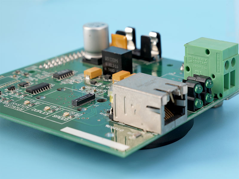
RJ45 PCB Connector Ethernet Layout Guidelines
RJ45 connectors are the most widely used Ethernet connectors in networking equipment. When designing a pcb mount ethernet connector, engineers must follow layout guidelines to ensure reliable performance.
Key layout recommendations include:
- Maintain short trace length between PHY and connector
- Avoid crossing split planes
- Place magnetics close to connector
- Ensure proper shielding grounding
These layout strategies significantly reduce EMI noise.
M12 Ethernet PCB Connector Mechanical Constraints
In industrial environments, m12 ethernet connector pcb designs are widely used due to their rugged construction and IP-rated protection.
M12 connectors are typically used in:
- Industrial automation
- Robotics communication
- Factory Ethernet networks
- Outdoor communication equipment
Their threaded locking design ensures vibration resistance and mechanical stability.
EMI Shielding Requirements in Ethernet PCB Connectors
Ethernet interfaces can act as antennas if shielding is poorly implemented. Effective EMI mitigation includes:
- Shielded connector housings
- Ground stitching vias around connectors
- Proper chassis grounding
- Isolation transformers
These techniques improve EMC compliance in industrial devices.
How EBest Solves Ethernet Connector PCB Design Challenges
EBest engineering teams assist customers in solving Ethernet PCB design problems through:
- Differential impedance calculation
- Connector footprint verification
- EMC design optimization
- Professional DFM analysis
Our engineers collaborate directly with customers to ensure ethernet connector pcb design reliability before manufacturing begins.
If you need professional ethernet connector pcb design support, EBest engineers are ready to assist.
Why Is Ethernet Connector PCB Prototyping Critical for Hardware Development?
Ethernet connector PCB prototyping allows engineers to verify electrical performance, connector compatibility, and mechanical stability before mass production. Rapid prototyping significantly reduces development risks and accelerates product validation.
Why Engineers Prototype Ethernet PCB Connectors
Prototype testing helps engineers confirm:
- Ethernet signal integrity
- Connector fit accuracy
- Mechanical mounting reliability
- EMI performance
Without proper prototype validation, small layout errors may cause costly redesign cycles.
Common Prototype Issues With PCB Mount Ethernet Connectors
During early hardware development, engineers frequently encounter:
- Connector pin alignment errors
- Incorrect footprint dimensions
- Signal integrity degradation
- Mechanical interference with enclosure design
These problems are common when working with complex connectors like ethernet connector female pcb components.
Industrial Ethernet Prototype Requirements
Industrial Ethernet applications often require more rigorous validation.
Typical test items include:
- Environmental stress testing
- Vibration reliability
- Signal transmission verification
- Connector durability testing
These tests ensure the device performs reliably in harsh industrial environments.
How EBest Accelerates Ethernet Connector PCB Prototyping
EBest supports rapid hardware development with:
- Fast PCB prototyping
- Engineering review before production
- Electrical testing verification
- Mechanical connector validation
Our rapid manufacturing workflow helps engineers validate ethernet connector pcb prototypes quickly and reliably.
If you are developing a networking device and require ethernet connector pcb prototype services, EBest can provide fast engineering support.
What Are the Challenges in Ethernet Connector PCB Assembly?
Ethernet connector PCB assembly requires precise soldering, connector alignment, and electrical testing. Because connectors are mechanical components subjected to insertion forces, assembly reliability is extremely important.
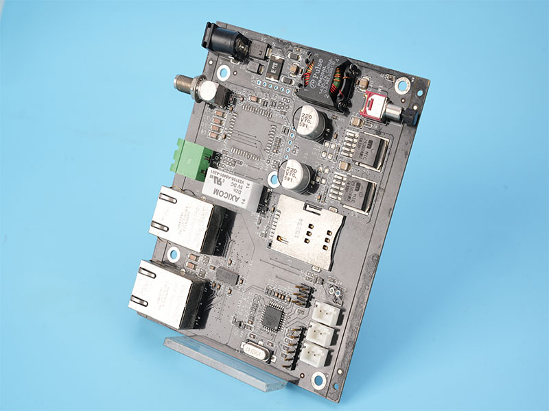
RJ45 PCB Connector Assembly Issues
RJ45 connectors are usually through-hole components. Common assembly challenges include:
- Poor solder wetting
- Incomplete hole fill
- Connector misalignment
These issues may lead to unstable Ethernet connections.
M12 Ethernet Connector PCB Mount Assembly Challenges
M12 connectors require robust mechanical fixation. During assembly, engineers must consider:
- Connector torque resistance
- Mechanical reinforcement
- Waterproof sealing requirements
These connectors are commonly used in ip67 ethernet connector pcb mount applications.
Through-Hole vs SMT Ethernet Connector Assembly
| Assembly Type | Advantages | Typical Applications |
|---|---|---|
| Through-Hole Connector | Strong mechanical reliability | Industrial devices |
| SMT Ethernet Connector | Compact layout | Consumer electronics |
| Hybrid Connector | Combined electrical + mechanical benefits | Industrial networking |
Selecting the correct assembly method improves product durability.
How EBest Ensures Reliable Ethernet PCB Connector Assembly
EBest implements strict quality control during connector assembly.
Key processes include:
- Automated optical inspection (AOI)
- X-ray inspection for solder joints
- Functional Ethernet testing
- Connector pull strength testing
These measures guarantee high reliability in ethernet connector pcb assembly projects.
Why Choose EBest for Ethernet Connector PCB Manufacturing?
Ethernet connector PCB technology plays a critical role in modern electronic communication systems. These PCBs integrate Ethernet connectors directly onto the board to enable reliable data transmission between devices, industrial equipment, and networking infrastructure. This article explains how Ethernet connector PCBs are designed, prototyped, assembled, and optimized for high-reliability applications.
In today’s hardware development environment, engineers frequently face challenges such as connector footprint mismatches, signal integrity problems, mechanical stress, and EMI interference. Solving these issues requires experienced engineering support and manufacturing expertise.
EBest specializes in ethernet connector pcb manufacturing, prototype services, and assembly solutions. Our engineering team supports industrial networking projects with fast delivery, robust design verification, and reliable PCB assembly processes.
Our advantages include:
1+3 engineering service model
One customer engineer works with three internal specialists to ensure full technical support.
Free DFM review and BOM optimization
Our engineers identify potential manufacturing issues early.
One-stop PCB and PCBA manufacturing
Services include PCB fabrication, component sourcing, assembly, and testing.
Fast PCBA delivery
Most orders are completed within 1.5 weeks.
Digital manufacturing system
Our MES system enables 5-second traceability for each production process.
Certified manufacturing quality
- ISO9001
- ISO13485
- IATF16949
- AS9100D
These certifications ensure reliable manufacturing for industrial and high-reliability electronics.
How Do You Route Differential Pairs for Ethernet Connector PCB?
Correct differential pair routing is essential for Ethernet performance.
Design rules include:
- Maintain 100Ω differential impedance
- Match trace lengths
- Avoid sharp corners
- Maintain consistent reference planes
These guidelines help maintain signal quality across the Ethernet interface.
What Is the Pinout of an Ethernet PCB Connector?
Typical ethernet pcb connector pinout follows the standard Ethernet wiring scheme.
For example, in RJ45 connectors:
| Pin | Signal |
|---|---|
| 1 | TX+ |
| 2 | TX- |
| 3 | RX+ |
| 6 | RX- |
Other pins are used for additional Ethernet functions depending on the interface standard.
What Are Industrial Applications for Ethernet Connector PCB?
Ethernet connector PCBs are widely used across multiple industries.
Medical Equipment
Medical diagnostic devices rely on Ethernet connectivity for secure data transfer between instruments and hospital systems.
Aerospace Systems
Aircraft communication modules often use rugged Ethernet connectors for reliable networking.
Industrial Automation
Factory equipment such as PLC controllers and robotic systems depend on industrial Ethernet networks.
Robotics Systems
Autonomous robots rely on Ethernet communication for high-speed data exchange.
EBest provides ethernet connector pcb manufacturing, prototype development, and assembly services for industrial networking applications. If you are looking for a professional ethernet connector pcb manufacturer, our engineering team is ready to support your project. Please contact us for technical assistance or order inquiries via sales@bestpcbs.com.
FAQs About Ethernet Connector PCB
What is the difference between ethernet pcb connector and RJ45 connector?
RJ45 is a specific connector type used in Ethernet systems, while ethernet pcb connector refers to any connector mounted on a PCB to provide Ethernet connectivity.
What is the typical ethernet pcb connector pinout?
Most Ethernet connectors follow the standard twisted-pair Ethernet pin assignments defined in networking standards.
Can M12 ethernet connector pcb support industrial environments?
Yes. M12 connectors are designed for industrial applications and provide high vibration resistance and waterproof protection.
What is the difference between pcb mount ethernet connector and cable connector?
A PCB mount connector is soldered directly onto the circuit board, while cable connectors terminate Ethernet cables externally.
How to design ethernet connector pcb routing correctly?
Proper design requires controlled impedance routing, differential pair matching, and EMI shielding techniques.