Drone PCB is the central nervous system of any Unmanned Aerial Vehicle (UAV), integrating flight controllers, sensors, and power systems onto a compact board. This article provides a comprehensive guide to drone PCB technology, covering design principles, assembly challenges, and how professional end-to-end services ensure optimal performance, reliability, and cost-effectiveness for your UAV projects.
Even experienced UAV teams encounter recurring PCB-level issues that directly limit flight stability, reliability, and scalability.
- Signal interference: Noise and crosstalk disrupt communication between flight controllers, ESCs, and receivers.
- Miniaturization limits: Compact mini drone PCB or ESP32 layouts force compromises in thermal and RF performance.
- Vibration failures: Standard drone PCB assembly cracks solder joints under sustained high-frequency vibration.
- Rising costs: Drone PCB price escalates from prototype to production due to redesigns and poor DFM.
- Fragmented sourcing: Separate PCB design, manufacturing, and assembly create delays and quality risks.
The most reliable path forward is an end-to-end drone PCB partner that controls design, fabrication, and assembly as a single system.
- Signal-integrity-driven design: Controlled impedance, optimized stack-ups, and EMI mitigation reduce noise at the source.
- HDI integration: Advanced HDI enables higher density without sacrificing electrical or thermal stability.
- Ruggedized assembly: Reinforced soldering, underfill, and conformal coating improve vibration and environmental resistance.
- Cost-engineered manufacturing: DFM-focused layouts stabilize pricing from PCB prototype to volume production.
- Single-source delivery: Unified design, fabrication, sourcing, and assembly shorten lead time and ensure consistency.
EBest Circuit (Best Technology) is a professional and reliable partner specializing in end-to-end drone PCB solutions. It is worth noting that our factory holds ISO 13485 and AS9100D certifications. We combine deep expertise in UAV-specific design challenges with advanced manufacturing capabilities to deliver high-performance, reliable circuit boards. From initial custom drone PCB concepts to volume production and assembly, we ensure your project soars on a foundation of quality and innovation. For inquiries, please contact us at sales@bestpcbs.com.
What Is a Drone PCB and Why Is It Central to UAV Electronics?
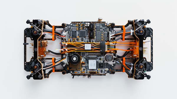
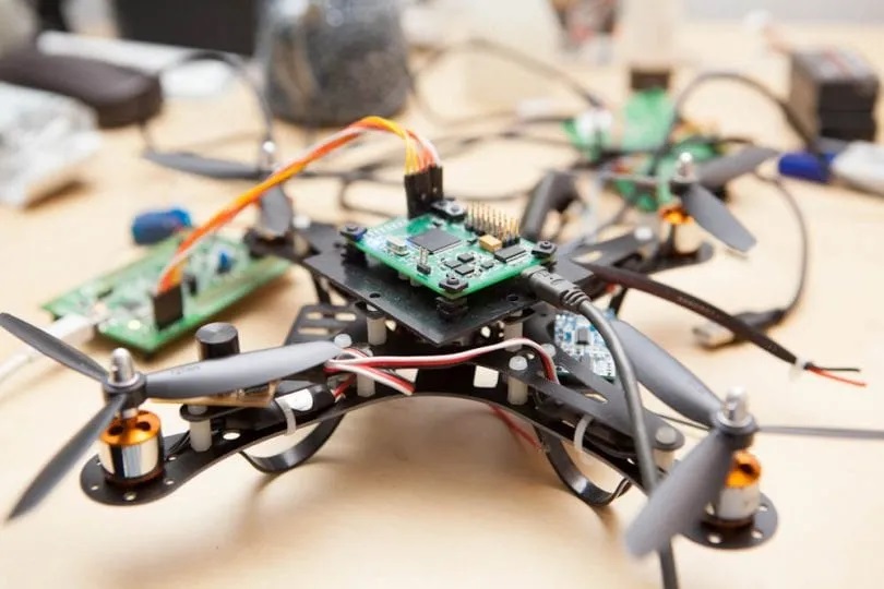
A Drone PCB (Printed Circuit Board) is the foundational platform that mechanically supports and electrically connects all critical electronic components of an unmanned aerial vehicle. It is far more than just a board; it’s the integrated system housing the flight controller, Electronic Speed Controllers (ESCs), power distribution network, sensors, and communication modules. Its centrality cannot be overstated—the drone PCB design dictates the weight, size, reliability, and ultimately the flight performance of the entire system.
- Integration Hub: It consolidates disparate systems (power, control, sensing) into a single, compact unit, which is crucial for mini drone PCB applications.
- Signal Highway: Provides controlled pathways for power and high-speed data signals between the processor, sensors, and motors.
- Structural Element: In many designs, especially PCB drone frame or integrated PCB drone concepts, the PCB itself acts as a structural part of the drone’s chassis.
- Thermal Management Base: Dissipates heat from powerful components like the processor and voltage regulators.
In essence, the quality and design of the drone PCB board directly determine a UAV’s intelligence, stability, and endurance. A poorly designed board can lead to catastrophic failure, while an optimized one enables advanced features and reliable operation.
How Does Drone PCB Design Impact Flight Stability and Signal Reliability?
Drone PCB design directly determines how stable a UAV flies and how reliably its control and sensor signals behave under real-world conditions.
At a high level, key layout decisions affect both mechanical balance and electrical integrity, as summarized below.
Key Drone PCB Design Factors and Their Effects
| Design Factor | Impact on Flight Stability | Impact on Signal Reliability |
|---|---|---|
| Component Placement | Affects center of gravity balance | Controls sensor trace length |
| Power Distribution Network (PDN) | Prevents voltage drops under load | Reduces power-related noise |
| Grounding Scheme | Stabilizes sensor reference levels | Ensures clean return paths |
| RF & EMI Shielding | Protects compass accuracy | Prevents signal dropouts |
Beyond these high-level effects, each factor introduces physical consequences that must be addressed during schematic and layout development.
- Component placement influences both mechanical balance and electrical path length, directly affecting sensor accuracy and response time.
- PDN design determines whether the processor and sensors remain stable during rapid throttle changes and high-current motor operation.
- Grounding strategy defines signal reference quality and plays a decisive role in EMI suppression and crosstalk control.
- RF and EMI shielding isolates sensitive navigation and communication circuits from high-noise power and motor domains.
The objective of a professional drone PCB schematic and layout is to minimize electrical noise, maintain clean power delivery, and allow high-speed digital, RF, and analog circuits to coexist without interference. This level of integration and foresight is typically beyond what generic low-cost drone PCB design services can provide.
What Does a Drone PCB Schematic Typically Include in Modern UAV Systems?
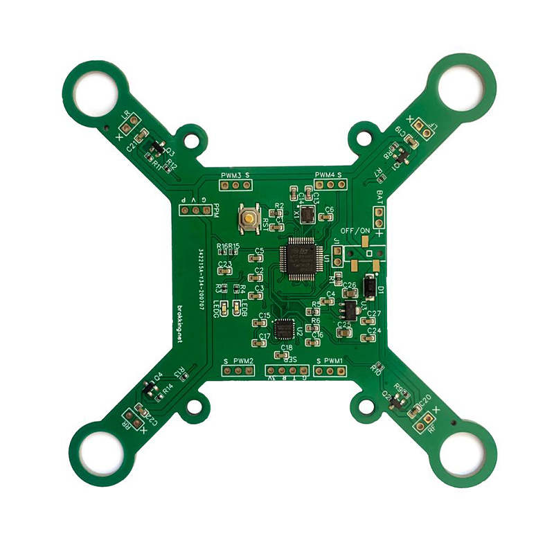
A modern drone PCB schematic is a detailed electrical blueprint that defines every connection and component in the system. It serves as the contract between the designer and the drone PCB manufacturer. For a typical flight controller-centric board, it includes several key subsystems:
- Flight Controller (FC) Core: The main microprocessor (often an STM32 or similar ARM Cortex-M) with its associated crystal oscillators, decoupling capacitors, and boot configuration circuits.
- Sensor Suite: Dedicated circuits for the Inertial Measurement Unit (IMU—gyroscope & accelerometer), barometer, and sometimes a magnetometer, with careful attention to I2C/SPI bus routing and noise isolation.
- Power Management Unit (PMU): This includes voltage regulators (e.g., converting LiPo 12V to 5V and 3.3V), VCC in PCB board drone distribution networks, and often battery monitoring circuits.
- Motor Control Interfaces: Connectors and driver circuits linked to the Electronic Speed Controllers (ESCs). For integrated PCB motor drone designs, the ESCs may be directly on the board.
- Communication Modules: Circuits for the radio control receiver (e.g., PWM, SBUS, CRSF), telemetry (e.g., ESP8266 for WiFi), and sometimes FPV video transmitters.
- Peripheral Interfaces: Headers for GPS modules, camera PCB module drone control (like for a camera PCB module drone 2302a), LED strips, and serial ports (UARTs) for expansion.
- USB Connectivity: A circuit for connecting to a ground station for configuration and firmware updates.
A comprehensive schematic is the first and most crucial step in a successful end-to-end drone PCB service, ensuring all functional requirements are captured before layout begins.
What Challenges Exist in Mini Drone PCB Layout and Component Integration?
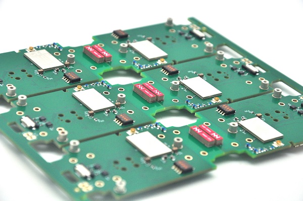
Designing a mini drone PCB for compact UAVs presents a unique set of challenges where every square millimeter counts. The primary struggle is balancing extreme miniaturization with uncompromised electrical and thermal performance.
- Extreme Density: Fitting an entire flight controller, radio, and sometimes ESCs onto a PCB for small drone requires using the smallest package components (01005, QFN, BGA), demanding high-precision manufacturing.
- Thermal Management in Confined Space: High-performance components generate heat in a very small area with limited airflow, risking thermal throttling or failure. Strategic placement and thermal vias are critical.
- Signal Integrity at High Density: With traces running extremely close together, the risk of crosstalk and EMI increases dramatically. Careful drone PCB layout, controlled impedance, and proper grounding are non-negotiable.
- Power Delivery Network (PDN) Design: Thin traces have higher resistance, leading to unwanted voltage drops during high-current events (like motor spikes). The PDN must be carefully modeled and designed with wide traces or power planes.
- Manufacturability and Reliability: A highly dense PCB board prototype may be functional, but ensuring it can be reliably assembled in volume and withstand real-world vibration (PCB drone motor forces) requires expert drone PCB assembly knowledge.
Overcoming these challenges often necessitates the use of HDI (High-Density Interconnect) technology, which is why partnering with experienced high density PCB suppliers for uav and drone systems is a strategic advantage for miniaturized drones.
How Does Drone PCB Assembly Affect Reliability in High-Vibration Environments?
Drone PCB assembly is the process where design meets reality, and it is the decisive factor for reliability in the harsh, high-vibration environment of a UAV. Even a perfect design can fail if assembled incorrectly.
- Solder Joint Integrity: Standard solder joints can fatigue and crack under constant vibration. Techniques like using higher-grade solder paste, precise reflow profiles, and applying underfill to large Ball Grid Array (BGA) components are essential.
- Component Securing: Larger components (connectors, capacitors) should be mechanically secured with adhesive in addition to solder. This is critical for any drone flight controller PCB.
- Conformal Coating: Applying a thin polymeric waterproof coating for PCB drones protects against moisture, dust, and chemical contaminants. It also provides minor mechanical stabilization to small components.
- Rigorous Inspection and Testing: Post-assembly, boards must undergo Automated Optical Inspection (AOI) and X-ray inspection (for BGAs) to find hidden faults. Functional testing under simulated vibration is ideal.
- Material Selection: Using boards with higher TG (Glass Transition Temperature) materials and choosing components rated for automotive or industrial temperature/vibration ranges enhances longevity.
A professional assembly service understands that a drone PCB for sale must be built to survive the real world, not just pass bench tests. This focus on ruggedization is what separates a hobbyist board from a professional-grade product.
What Determines Drone PCB Price From Prototype to Mass Production?
Drone PCB price is shaped by different cost drivers at each production stage, and understanding these shifts is essential for accurate budgeting and long-term cost control.
At a high level, the main cost dynamics across prototype, pilot, and mass production phases can be summarized below.
Drone PCB Cost Drivers by Production Phase
| Phase | Key Cost Drivers | Cost Optimization Focus |
|---|---|---|
| Prototype | Setup fees, complexity, small-batch components | Standard materials, no rush |
| Low-Volume Pilot | Panel inefficiency, manual assembly, testing | Panel alignment, assembly simplification |
| Mass Production | Material scale, automation, sourcing efficiency | DFM, component standardization |
Beyond these summaries, the dominant cost factor throughout all stages is design complexity.
- Early prototypes are sensitive to layer count, special materials, and expedited schedules.
- Pilot runs reveal whether panelization and assembly choices scale efficiently.
- Mass production rewards designs that align with automated processes and standardized components.
A simple 2-layer DIY drone PCB costs a fraction of a high-layer HDI or rigid-flex design, not because of volume alone, but because complexity compounds at every manufacturing step. Engaging a drone PCB manufacturer early for Design for Manufacturability (DFM) review remains the most effective way to control costs while preserving performance and reliability.
Why Do OEMs Choose High Density PCB Suppliers for UAV and Drone Systems?
Original Equipment Manufacturers (OEMs) developing advanced UAVs increasingly turn to specialized high density PCB suppliers for uav and drone systems for one overarching reason: enabling innovation within strict physical constraints. HDI technology is not just an option; it’s a necessity for next-gen drones.
- Miniaturization: HDI allows for more components in less space via microvias and finer traces/spacing, enabling smaller, lighter drones.
- Enhanced Performance: Shorter signal paths from HDI routing improve signal integrity for high-speed processors and clean sensor data, which is crucial for autonomy and stability.
- Increased Reliability: The dense interconnect structure and advanced materials often used in HDI boards can lead to a more robust and reliable drone PCB board.
- Functional Integration: HDI facilitates the creation of integrated PCB drone frames and systems-on-a-board, reducing the need for multiple interconnected PCBs and connectors—potential points of failure.
- Long-Term Partnership: These suppliers possess specific expertise in thermal management, impedance control, and RF design essential for UAVs, becoming valuable technical partners rather than just board fabricators.
For OEMs looking to build competitive, feature-rich, and reliable drones, partnering with a capable HDI supplier is a strategic investment in the product’s core technology.
In summary, the Drone PCB is the unsung hero of UAV technology, a sophisticated platform where electrical engineering, mechanical design, and software converge to create flight. From the initial drone PCB schematic to the final drone PCB assembly, every step in its creation profoundly impacts the drone’s performance, reliability, and success.
Navigating the complexities of drone PCB design, miniaturization, vibration resistance, and cost-effective production requires a partner with specialized expertise. EBest Circuit (Best Technology) provides precisely this—true end-to-end drone PCB services. We combine expert design consultation with advanced manufacturing and rigorous assembly to transform your concept into a robust, high-flying reality. Pls feel free to contact us anytime for your drone PCB project via sales@bestpcbs.com.
FAQs
How to read signal of drone PCB?
Reading signals on a drone PCB requires electronic test equipment. A digital multimeter can check for continuity and measure static voltages (like VCC in PCB board drone). To analyze dynamic communication signals (like PWM from a receiver or data on an SPI bus), an oscilloscope is essential. It visually displays the voltage of a signal over time, allowing you to verify its shape, timing, and integrity. For decoding specific digital protocols (SBUS, I2C), a logic analyzer is the appropriate tool.
What is VCC in PCB board drone?
VCC in a PCB board drone is a standard electronics label denoting the main positive supply voltage rail for integrated circuits. It stands for “Voltage at the Common Collector,” tracing back to transistor terminology. On a drone board, you might find multiple VCC rails, such as “5V_VCC” for peripherals and “3.3V_VCC” for the microcontroller and sensors. It is the primary power source that “drives” the active components on the board.