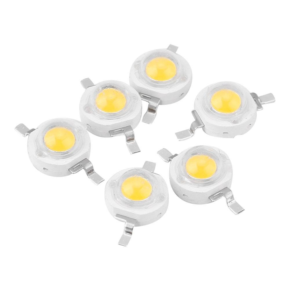
What is Chip On Board COB MCPCB?
COB MCPCB, known as “Chip-On-Board” Metal Core PCB, is a type of MCPCB used in thermoelectric separation application. By using COB MCPCB, the micro-chip (also known as “die”) directly touch the metal core where the heat dissipate, and electrically interconnect the trace of circuit board (wire-bonding) so that power supply can be provided.
In normal MCPCB, there’s a dielectric layer between trace copper and metal core, and the thermal conductivity is limited by that dielectric layers, so value can only be 1~3 W/m.K. But using COB MCPCB, there’s no such dielectric layer because chip (die) direct touch the metal core, so thermal conductivity value of COB MCPCB will be almost the same one of metal core material itself. The normal material of metal core is aluminum, so thermal conduviity of COB MCPCB is more than 200W/m.K.
COB MCPCB (Chip on Board)
What are the COB Wire Bonding Processes?
COB process consists of three main categories to perform when manufacturing the Chip-on-Board:
1st: die mount or die attach;
2nd: wire bonding;
3rd: the encapsulation of die wires.
By using wire bonding & epoxy packaging then directly embedded on MCPCB, this practice can extend the lifespan of LED and unified light emission.
According to process and material, COB MCPCB applications can be categorized into two types: Mirror Aluminum and silver or gold platting aluminum, or silver plating mirror aluminum PCB.
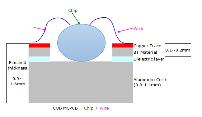
Structure of COB MCPCB
Advantage of utilizing COB MCPCB
- Excellent heat dissipation
- High thermal conductivity: 137W/m.K
- Higher reliability with better heat dispatch and small number of solder joint.
- Provide enhanced reliability and lifespan of LED
- Easy assembly for high powers LEDs
- High quality material and production process allows easy assembly and substantial reduce the error percentage in assembly process
- Substantially reduced space and cost
- With better security protection (difficult to hack using reverse engineering)
- Shorter time to the market
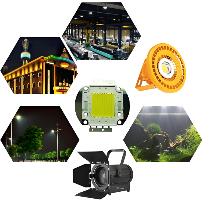
Application of COB MCPCB
- High Power LED (up to 200W)
- LED Backlight for LED TV
- LED Front Light for E-Book
- Agriculture & Horticulture Lighting
- Street & Parking Lot Lighting
- Automotive
- Power Supply
- ustomer Electronics Lighting
- Other products that require thermal solutions
FAQs about COB MCPCBs
1. What is the difference between a standard MCPCB and a COB MCPCB?
A standard MCPCB (Metal Core PCB) usually has SMT (Surface Mount Technology) components soldered onto a dielectric layer. In contrast, a COB (Chip-on-Board) MCPCB allows the LED semiconductor chip to be mounted directly onto the metal core or into a recessed “well.” This removes the thermal resistance of the LED package itself, allowing for much higher power density.
2. Why is thermal conductivity so important for COB MCPCBs?
Since COB LEDs pack many light-emitting diodes into a very small area, they generate intense localized heat. If this heat isn’t dissipated, the LED’s lifespan and brightness (luminous flux) drop rapidly. COB MCPCBs use materials like Aluminum or Copper to pull heat away from the chips at rates significantly higher than standard FR4 boards.
3. What are the common base materials used in COB MCPCBs?
- Aluminum: The most common and cost-effective choice for general lighting.
- Copper: Offers superior thermal conductivity but is heavier and more expensive; used for extreme high-power applications.
- Stainless Steel: Occasionally used for high-strength requirements, though it has poorer thermal properties than Aluminum.
4. What is a “Mirror Aluminum” COB MCPCB?
A Mirror Aluminum COB MCPCB features a highly reflective, polished surface. This design ensures that light emitted from the sides of the LED chips is reflected forward, increasing the overall light output efficiency (Lumen/Watt) by reducing light absorption by the board itself.
5. Can COB MCPCBs be used with high-voltage applications?
Yes, but they require a specialized dielectric layer. This layer must be thin enough to allow heat to pass through to the metal core, but thick enough to provide electrical insulation (dielectric breakdown voltage) to prevent short circuits, especially in AC-driven LED modules.
6. What are the main applications for COB MCPCB technology?
Because they offer high brightness in a compact footprint, they are the industry standard for:
- Automotive lighting (Headlights).
- Industrial high-bay lighting.
- Street lights and architectural floodlights.
- Commercial downlights and track lighting.