

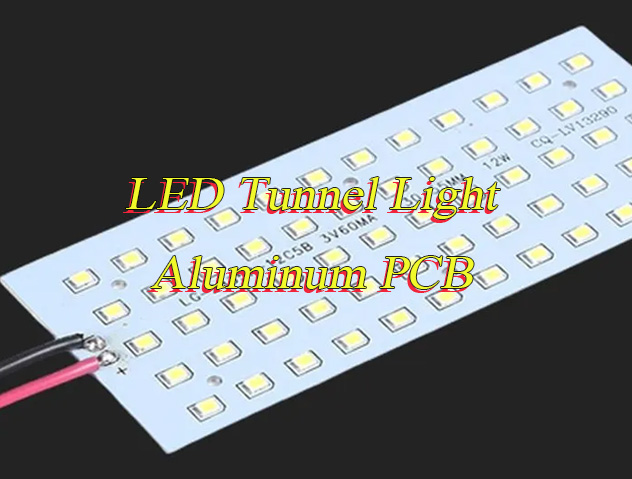
Why Is LED tunnel light aluminum PCB the key to solving thermal issues in tunnel lighting? If you’re a tunnel lighting engineer struggling with overheating LED fixtures and shortened lifespans, you know how critical a reliable LED tunnel light aluminum PCB is. For top-quality, on-time, cost-effective LED tunnel light aluminum PCB solutions, choose EBest, we offer superior quality control, fast lead times, optimized costs, professional service, and a stable supply chain. This blog breaks down everything you need to know about LED tunnel light aluminum PCBs, from thermal performance to design rules, material selection, and common pitfalls.
How Does Aluminum PCB Enhance Thermal Performance for LED Tunnel Lights?
Aluminum PCBs boost the thermal performance of LED tunnel lights mainly through their unique three-layer “sandwich” structure, which solves the heat buildup problem that troubles traditional PCBs in high-temperature tunnel settings. This structure includes a circuit layer, a dielectric layer, and a metal base layer, with each layer working together to enable efficient heat transfer.
The circuit layer, made of electrolytic copper foil with high thermal conductivity (398 W/(m·K)), quickly spreads heat horizontally from LED chips to avoid localized hotspots, critical for tunnel lights that run continuously. The middle dielectric layer, often made of ceramic-filled epoxy (1.0-3.0 W/(m·K) thermal conductivity), acts as a bridge, balancing electrical insulation and vertical heat transfer to the aluminum base without short circuits.
The aluminum alloy base layer, with a thermal conductivity of 180-200 W/(m·K), serves as an integrated heat sink to rapidly absorb and diffuse heat into the tunnel air. By minimizing thermal resistance and ensuring direct heat paths, this layered synergy keeps LED junction temperatures low even in 40-60℃ tunnels, maintaining stable performance and extending the service life of LED tunnel lights.
What Are the Key Design Rules for Aluminum PCBs in High-Temp Tunnel Environments?
High-temp tunnel environments (often 40-60℃) require strict design rules to ensure aluminum PCB reliability. Follow these guidelines:
- Optimize thermal path design: Ensure direct contact between LED chips and the aluminum base, and connect LED pads to large copper areas using thermal reliefs to balance soldering ease and heat transfer, minimizing thermal resistance effectively.
- Avoid overcrowding components: Space LED chips and other heat-generating parts (such as drivers) evenly, and keep LEDs away from PCB edges where heat dissipation is reduced, preventing localized hotspots that damage components.
- Use high-temperature-resistant materials: Select dielectric layers and solders rated for at least 105℃; for tunnels above 60℃, choose polyimide dielectric materials and specialized aluminum-compatible solders to withstand prolonged high temperatures.
- Incorporate thermal vias: Place 0.8-1.2mm diameter thermal vias near LED chips, space them 5-10mm apart, and fill them with solder to bypass the dielectric layer and speed up heat transfer to the aluminum base.
- Optimize copper foil design: Use 2oz (70μm) copper foil for most high-power tunnel LEDs (30-100W) to reduce line resistance and heat generation; for ultra-high-power setups (>100W), upgrade to 3oz (105μm) copper.
- Ensure proper insulation spacing: Maintain a minimum spacing of 2.5mm for high-voltage sections (such as AC drivers) to prevent creepage and short circuits, and ensure the dielectric layer thickness is at least 75μm in high-voltage areas.
- Design for mechanical stability: Choose 1.5-3.0mm thick aluminum substrates for high-power or dense LED layouts, reserve a 1mm copper-free area at the board edge to avoid copper layer warping during cutting, and use non-metallized holes for all PCB drilling.
- Account for thermal expansion: Match the thermal expansion coefficient of components (LEDs, drivers) with the aluminum PCB to reduce mechanical stress caused by temperature changes in tunnels, preventing solder joint cracking.
- Integrate dust and moisture protection: Design PCB layouts that accommodate conformal coatings (silicone or acrylic) and IP65+ enclosures, avoiding component placement in areas that are hard to coat or clean.
- Simplify maintenance access: Arrange components and thermal vias in easily accessible positions, avoiding dense layouts that block dust removal or inspection, ensuring routine maintenance can be performed efficiently.
How to Choose the Right Aluminum Substrate for LED Tunnel Light PCBs?
Selecting the right aluminum substrate ensures optimal performance and durability. Follow these steps:
- Select the right aluminum alloy: Choose 6061 alloy for most tunnel scenarios, as it balances excellent thermal conductivity (180-200 W/(m·K)) and mechanical strength; opt for 5052 alloy for humid tunnels to leverage its superior corrosion resistance against moisture damage.
- Match substrate thickness to LED power: Use 1.0-1.5mm for low-to-medium power (≤50W) tunnel lights, and 1.5-2.0mm for high-power (50-100W) setups to balance heat dissipation and structural stability.
- Prioritize thermal conductivity rating: Select substrates with a minimum thermal conductivity of 1.5 W/(m·K) for high-power LEDs; upgrade to 2.0 W/(m·K) or higher for tunnels with ambient temperatures above 50℃ to ensure efficient heat transfer.
- Verify compliance with industry standards: Ensure the substrate is RoHS-compliant to meet international environmental requirements for tunnel infrastructure, and confirm it meets IPC-2221 standards for PCB reliability in industrial settings.
- Consider surface treatment: Choose thermal oxidation or anodizing for the aluminum base to enhance heat dissipation efficiency and prevent corrosion, which is critical for tunnels with dust and moisture.
- Match thermal expansion coefficient (TEC): Select substrates with a TEC close to LED chips and drivers (8-10 ppm/℃) to reduce mechanical stress from tunnel temperature fluctuations, avoiding solder joint cracking.
What Dielectric Material Works Best for Aluminum PCBs in Tunnel Lighting?
The dielectric layer is critical for insulation and heat transfer, choose materials that balance thermal conductivity and reliability:
- Ceramic-filled epoxy: The most versatile and widely used dielectric material for LED tunnel light aluminum PCBs. It offers a balanced thermal conductivity (1.0-3.0 W/(m·K)) and excellent electrical insulation, making it ideal for most high-power tunnel LED setups (30-100W) and standard tunnel temperatures (40-60℃).
- Polyimide: The top choice for extreme high-temperature tunnels (above 60℃). It boasts superior heat resistance (withstands up to 200℃) and good mechanical flexibility, though its thermal conductivity (0.8-1.5 W/(m·K)) is slightly lower than ceramic-filled epoxy.
- BT resin: Perfect for humid or moisture-prone tunnels (e.g., underwater or coastal tunnels). It provides strong moisture resistance and stable thermal performance (1.0-1.8 W/(m·K)), suitable for medium-power LED setups that require long-term reliability in damp environments.
- Silicone-based dielectric: Ideal for tunnels with frequent temperature fluctuations. It has excellent thermal shock resistance, can withstand -60℃ to 180℃, and offers moderate thermal conductivity (0.6-1.2 W/(m·K)), preventing dielectric layer cracking from thermal stress.
- Alumina ceramic: Designed for ultra-high-power LED tunnel lights (>100W). It delivers exceptional thermal conductivity (3.0-5.0 W/(m·K)) and high insulation strength, though it is more rigid and requires specialized manufacturing to avoid brittleness.
- Epoxy-silicone hybrid: A cost-effective middle ground for tunnels with moderate heat and moisture. It combines the thermal conductivity of epoxy (1.2-2.0 W/(m·K)) with the moisture resistance of silicone, ensuring durability without excessive cost.
How Do Thermal Vias Improve Heat Dissipation in LED Tunnel Aluminum PCBs?
Thermal vias are tiny holes filled with conductive material, designed to conduct heat from the circuit layer to the aluminum substrate. Their advantages include:
- Shortened Thermal Conduction Path: Thermal vias bypass the dielectric layer, establishing a direct vertical thermal conduction channel between the circuit layer—where the LED chips are mountedand the aluminum substrate. This accelerates heat transfer to a rate three times faster than that achieved through traditional horizontal conduction alone.
- Reduction of Local Hotspots: By positioning thermal vias within a 3 to 5 mm radius of the LED chips, concentrated heat can be uniformly dispersed across the entire PCB board. This effectively prevents LED performance degradation and shortened lifespan caused by overheating, a critical factor for tunnel lighting equipment requiring continuous, long-duration operation.
- Enhanced Heat Dissipation for High-Power Devices: For LED tunnel lights with power ratings exceeding 50 watts, properly designed thermal vias can lower the LED junction temperature by 20 to 25°C, thereby ensuring stable operation even within tunnel environments where ambient temperatures range from 40 to 60°C.
- Optimized Via Specifications: It is recommended to utilize vias with a diameter of 0.8 to 1.2 mm and a pitch of 5 to 10 mm, filling them with solder to maximize thermal conductivity. If the vias remain unfilled, their thermal conduction efficiency can drop by as much as 40%, while simultaneously increasing the likelihood of voids forming within the solder joints.
- Synergistic Heat Dissipation with Aluminum Substrate: Thermal vias complement the inherent high thermal conductivity of the aluminum substrate (180–200 W/(m·K)), accelerating the diffusion of heat from the PCB surface into the surrounding tunnel air.
- Prevention of Thermal Stress Damage: By uniformly dispersing heat, thermal vias effectively mitigate mechanical stress caused by temperature differentials across the PCB surface. This prevents common issues such as solder joint cracking and PCB warping—problems frequently encountered during ambient temperature fluctuations within tunnel environments.
- Enhanced Long-Term Reliability: Well-positioned and properly filled thermal vias effectively slow down the thermal aging of the dielectric material, ensuring the sustained stability of insulation properties and, consequently, extending the overall service life of the aluminum-based PCB within the demanding conditions of a tunnel environment.
What Copper Thickness Is Ideal for High-Power LED Tunnel Light Aluminum PCB?
Copper thickness directly impacts current carrying capacity, heat dissipation, and long-term reliability of high-power LED tunnel light aluminum PCB, choose based on LED power, tunnel temperature, and current load for optimal performance:
- 1oz (35μm): Suitable for low-power LED tunnel lights (≤30W), such as small auxiliary tunnel sections. It balances cost and basic performance, but is not recommended for high-power setups as it risks overheating from insufficient current carrying capacity.
- 2oz (70μm): The ideal choice for most high-power LED tunnel lights (30-100W), the most common setup in highway and railway tunnels. It reduces line resistance, minimizes heat generation, improves heat conduction to the aluminum base, and avoids voltage drop issues common with thinner copper.
- 3oz (105μm): For ultra-high-power LED tunnel lights (>100W) or tunnels with ambient temperatures above 55℃. It handles high current loads (>5A) more effectively, further enhances thermal dissipation, and reduces long-term degradation, though it requires specialized manufacturing processes.
- 4oz (140μm): A specialized option for extreme scenarios, such as ultra-high-power tunnel lights (>150W) or industrial tunnels with continuous high-temperature operation. It maximizes current carrying capacity and heat transfer but increases manufacturing complexity and cost.
How to Prevent Overheating and Extend Lifespan of LED Tunnel Light Aluminum PCB?
Overheating is the primary cause of shortened lifespan and performance degradation in LED tunnel light aluminum PCBs, especially in high-temperature, continuous-operation tunnel environments. LED junction temperature directly affects lifespan, each 10°C increase can shorten LED life by 30-50%. The following practical, targeted steps prevent overheating, protect PCB components, and extend service life without unnecessary complexity.
- Optimize LED layout: Space LEDs evenly to avoid heat concentration, and keep them away from PCB edges (where heat dissipation is weaker) to prevent localized hotspots that damage components.
- Pair with heat sinks: Attach a finned heat sink to the aluminum base to increase heat dissipation area by 2-3x, accelerating heat transfer from the PCB to the tunnel air.
- Maintain regular cleaning: Dust buildup on the PCB surface can reduce heat dissipation by up to 50%, so clean debris every 6 months during routine maintenance.
- Select high-temperature components: Use LEDs, capacitors, and solders rated for at least 105℃ to avoid premature failure under prolonged tunnel heat.
- Ensure thermal via effectiveness: Keep thermal vias clear of dust and debris, and verify they are properly filled with solder to maintain efficient vertical heat transfer.
- Control current load: Avoid overloading the PCB beyond its rated current, as excessive current increases heat generation and degrades copper layers and dielectric materials.
- Apply conformal coating: A thin silicone or acrylic coating not only repels dust and moisture but also helps dissipate heat evenly across the PCB surface.
What Are Common Mistakes in Aluminum PCB Design for Tunnel Lighting?
Avoid these costly design mistakes to ensure PCB reliability in tunnel environments:
- Ignoring thermal via specifications: Placing thermal vias too far from LED chips (over 5mm) or using unfilled/undersized vias renders them ineffective, leading to localized hotspots and shortened LED lifespan.
- Using low-grade dielectric materials: Opting for cheap, low-temperature dielectric layers (instead of ceramic-filled epoxy or polyimide) causes rapid degradation in 40-60℃ tunnel environments, leading to insulation failure.
- Underestimating copper thickness: Using 1oz (35μm) copper for high-power LED tunnel lights (30W+) increases line resistance and heat generation, resulting in overheating and PCB damage.
- Neglecting environmental protection: Skipping conformal coating or using low-IP-rated enclosures exposes PCBs to tunnel dust and moisture, causing corrosion and electrical malfunctions.
- Mismatching aluminum alloy and tunnel conditions: Using 6061 alloy in humid tunnels (instead of corrosion-resistant 5052) leads to base layer rust and reduced heat dissipation efficiency.
- Overlooking insulation spacing: Failing to maintain 2.5mm minimum spacing for high-voltage sections increases the risk of creepage and short circuits in tunnel lighting systems.
- Disregarding thermal expansion matching: Choosing aluminum PCBs with a thermal expansion coefficient (TEC) far from LED chips causes solder joint cracking due to tunnel temperature fluctuations.
- Overcrowding components: Packing LED chips and drivers too closely blocks heat dissipation, creating hotspots that degrade PCB components over time.
How Does Aluminum PCB Compare to FR-4 for LED Tunnel Light Applications?
| Comparison Factor | Aluminum PCB | FR-4 PCB |
| Thermal Conductivity | 1.5-3.0 W/(m·K), excellent heat dissipation | 0.2 W/(m·K), poor heat dissipation |
| High-Temp Resistance | Withstands 105-150℃, ideal for tunnel environments | Withstands 85-100℃, prone to degradation in hot tunnels |
| LED Lifespan Impact | Extends LED lifespan by 30-50% via effective heat management | Shortens LED lifespan by 20-30% due to overheating |
| Mechanical Strength | High strength, resistant to vibration (critical for tunnels) | Low strength, prone to cracking from tunnel vibrations |
| Moisture Resistance | Good, when sealed properly | Poor, prone to water damage in humid tunnels |
How to Ensure Dust Resistance and Reliability in LED Tunnel Light Aluminum PCB?
Tunnels are typically dusty, high-vibration, and sometimes humid environments, which can cause dust accumulation, corrosion, and electrical malfunctions in LED tunnel light aluminum PCBs, directly affecting reliability and service life. The following targeted measures effectively enhance dust resistance and overall reliability, ensuring stable long-term operation of PCBs in harsh tunnel conditions.
- Apply conformal coating: Use silicone or acrylic conformal coating to form a thin, uniform protective layer on the PCB surface, effectively repelling dust, moisture, and contaminants without affecting heat dissipation.
- Adopt IP65+ rated enclosures: Choose high-seal enclosures with IP65 or higher protection rating to prevent dust particles from entering and accumulating on PCB components, which is critical for mining and highway tunnels.
- Select dust-resistant components: Optimize for LEDs, connectors, and capacitors with sealed designs to avoid dust buildup on contact points, preventing poor contact and electrical failures.
- Optimize PCB layout for cleaning: Avoid dense component placement in hard-to-reach areas, reserve reasonable gaps between components, and design smooth surfaces to facilitate routine dust removal during maintenance.
- Strengthen aluminum base protection: Use anodized or thermally oxidized surface treatment on the aluminum base to enhance corrosion and dust resistance, extending the substrate’s service life in dusty environments.
- Regular maintenance and inspection: Inspect PCBs every 6 months to clean surface dust, check for conformal coating damage, and ensure enclosure seals are intact, preventing dust from penetrating over time.
What Thermal Interface Materials (TIM) Complement Aluminum PCBs in Tunnels?
Thermal Interface Materials (TIMs) play a crucial role in bridging gaps between aluminum PCBs and heat sinks, eliminating air pockets that hinder heat transfer. Choosing the right TIM based on tunnel temperature, humidity, and vibration conditions ensures optimal thermal efficiency and long-term reliability of LED tunnel lighting systems.
- Thermal Grease: Ideal for standard tunnel environments with ambient temperatures of 40-60℃. It fills micro-gaps between the PCB and heat sink, improving thermal conductivity by 20-30%, and is cost-effective for most highway and railway tunnel lighting setups.
- Thermal Pads: Suitable for humid or moisture-prone tunnels (e.g., underwater or coastal tunnels). Non-conductive, moisture-resistant, and easy to install, they prevent electrical short circuits while maintaining stable heat transfer, even in damp conditions.
- Phase-Change Materials (PCMs): Best for tunnels with frequent temperature fluctuations. They absorb excess heat during peak operating hours and release it when temperatures drop, keeping LED junction temperatures stable and reducing thermal stress on PCBs.
- Thermal Adhesive: Designed for vibration-prone tunnels (e.g., railway or mining tunnels). It securely bonds the aluminum PCB to the heat sink, preventing gaps caused by vibration and ensuring consistent heat transfer, which is critical for continuous operation.
- High-Temp Thermal Silicone: Suitable for extreme high-temperature tunnels (above 60℃). It withstands -40℃ to 180℃ temperature ranges, maintains stable thermal conductivity, and adheres well to aluminum substrates without primer, ideal for harsh tunnel conditions.
- Ceramic TIMs: For ultra-high-power LED tunnel lights (>100W). They offer high thermal conductivity (2-5 W/(m·K)), excellent heat resistance, and non-flammability, ensuring efficient heat transfer for high-load tunnel lighting systems like those used in large-scale tunnel projects.
FAQ About LED Tunnel Light Aluminum PCB
Q1: How long does an LED tunnel light aluminum PCB last in a high-temp tunnel?
A1: With proper design and maintenance, EBest’s LED tunnel light aluminum PCBs last 8-10 years in high-temp tunnels (40-60℃), 2-3x longer than FR-4 PCBs.
Q2: Can aluminum PCBs be used in underwater tunnel lighting?
A2: Yes, when sealed with IP68 enclosures and conformal coating, aluminum PCBs are fully waterproof and suitable for underwater tunnel environments.
Q3: What’s the maximum LED power an aluminum PCB can handle for tunnel lights?
A3: EBest’s aluminum PCBs can handle up to 200W per board, making them suitable for high-power tunnel lighting systems.
Q4: How often should I inspect LED tunnel light aluminum PCBs?
A4: Inspect PCBs every 6 months for dust buildup, conformal coating damage, and thermal via blockages to ensure optimal performance.
Q5: Do aluminum PCBs require special manufacturing for tunnel lighting?
A5: Yes, tunnel-specific aluminum PCBs need high-temperature dielectric materials, optimized thermal via design, and dust-resistant coatings, all of which EBest specializes in.