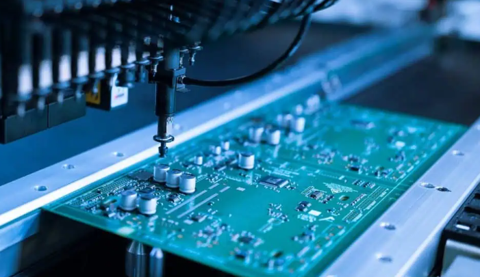
Medical Device PCB represents the fundamental backbone of modern healthcare technology, serving as the critical nervous system that enables precise signal processing, data management, and control functions in medical equipment. These specialized printed circuit boards transform electronic concepts into life-saving realities, from portable diagnostic devices to sophisticated surgical robotics. This comprehensive guide explores how custom medical device PCB solutions combined with rapid prototyping capabilities are revolutionizing healthcare technology development.
What struggles do medical device manufacturers typically face when developing PCB solutions?
- Prototyping Delays: Traditional PCB fabrication cycles often require 4-6 weeks, significantly slowing innovation cycles and product validation processes.
- Regulatory Complexity: Navigating ISO 13485, FDA regulations, and other medical standards requires specialized knowledge that many PCB manufacturers lack.
- Technical Specialization: Medical devices demand capabilities like HDI technology, impedance control, and biocompatible materials that exceed standard PCB requirements.
- Supply Chain Reliability: Component sourcing challenges and quality consistency issues can derail production timelines and impact device reliability.
- Cost Management: Balancing advanced technical requirements with budget constraints, especially for complex devices requiring rigid-flex designs or specialized materials.
How can these challenges be effectively addressed?
- Rapid Prototyping Services: Leverage manufacturers offering 48-hour to 7-day quick-turn PCB prototypes to accelerate development cycles without compromising quality.
- Regulatory Expertise: Partner with ISO 13485-certified manufacturers with proven experience navigating medical device compliance requirements across different markets.
- Technical Specialization: Select manufacturers with specific capabilities in HDI, rigid-flex, and RF PCBs tailored to medical applications.
- Supply Chain Integration: Choose partners offering turnkey solutions with component sourcing, assembly, and testing services to ensure end-to-end quality control.
- Cost-Optimized Strategies: Implement design-for-manufacturability approaches that balance performance requirements with production efficiency.
At EBest Circuit (Best Technology), we understand these challenges intimately. With over two decades of specialized experience in medical device PCB manufacturing, we’ve developed a comprehensive approach that combines technical excellence, regulatory expertise, and accelerated prototyping capabilities to help our healthcare technology partners bring innovative devices to market faster without compromising safety or performance. Our ISO 13485-certified facilities and dedicated medical PCB team ensure that your projects meet the most stringent quality standards while benefiting from rapid turnaround times that can compress development cycles by up to 70%. A warm welcome to contact our medical PCB specialists at sales@bestpcbs.com to discuss how our custom solutions and quick prototype services can accelerate your medical device development.
What Is a Medical Device PCB?
A Medical Device Printed Circuit Board (PCB) serves as the fundamental platform that hosts and connects electronic components in medical equipment, enabling everything from basic monitoring to complex surgical procedures. In healthcare applications, PCBs transcend their conventional role to become critical components where reliability directly impacts patient safety and treatment outcomes. These specialized circuit boards form the electronic backbone of modern medical technology, transforming conceptual healthcare solutions into practical, life-saving devices.
The distinction of medical device PCBs lies in their exceptional requirements for precision, reliability, and safety. Unlike consumer electronics where occasional failures may cause inconvenience, medical PCB failures can have grave consequences. This fundamental difference drives the entire approach to medical PCB design, manufacturing, and validation. Medical PCBs must operate flawlessly in diverse environments—from controlled hospital settings to emergency field use—while maintaining consistent performance under potentially stressful conditions.
Key Characteristics of Medical-Grade PCBs
- Stringent Quality Standards: Medical PCBs adhere to rigorous quality management systems like ISO 13485 and specific FDA regulations that far exceed standard industrial requirements.
- Biocompatibility Compliance: Boards intended for implantable devices or those contacting patients must meet ISO 10993 biocompatibility standards to ensure they won’t harm human tissues.
- Enhanced Reliability Measures: Medical PCBs incorporate redundant circuits, higher-grade components, and robust designs to achieve failure rates measured in parts per million rather than percentages.
- Advanced Material Selection: Medical applications often require specialized substrates like polyimide for flexible circuits, ceramic-filled laminates for thermal management, or low-loss materials for high-frequency applications.
- Comprehensive Testing Protocols: Each medical PCB undergoes extensive testing including environmental stress screening, burn-in testing, and functional validation to ensure flawless operation in critical healthcare scenarios.
Medical PCB Applications Across Healthcare Settings
Table: Medical PCB Applications by Healthcare Setting
| Healthcare Setting | PCB Applications | Key Requirements |
|---|---|---|
| Hospitals & Clinics | Patient monitors, imaging systems, diagnostic equipment | High reliability, EMI control, long life |
| Portable/Home Use | Wearable monitors, portable diagnostic devices, medication dispensers | Small size, low power, robust |
| Surgical Environments | Surgical robots, endoscopic systems, laser treatment devices | Accurate timing, clean signals, fast response |
| Implantable Devices | Pacemakers, neurostimulators, drug delivery systems | Ultra-small, biocompatible, long-life |
| Laboratory Settings | Blood analyzers, PCR systems, laboratory automation | High accuracy, thermal stability, clean operation |
The evolution of medical device PCBs continues to accelerate with trends toward miniaturization, interconnectivity, and intelligent functionality. Modern medical PCBs increasingly incorporate wireless communication modules, AI chips for predictive analytics, and sophisticated sensors that enable new healthcare paradigms like remote patient monitoring and personalized treatment approaches. This technological progression makes expert PCB partnership increasingly critical for medical device innovators seeking to translate cutting-edge healthcare concepts into practical, reliable clinical solutions.

What Factors Define High-Quality Medical Device PCB Design for Clinical Use?
High-quality medical device PCB design transcends conventional circuit board layout by incorporating clinical usability, patient safety, and regulatory compliance as fundamental design parameters. These factors distinguish medical-grade PCB designs from standard commercial designs, creating a foundation for reliable healthcare technology that meets the rigorous demands of clinical environments. The design phase represents the most critical opportunity to implement features that ensure medical device safety, performance, and manufacturability.
Critical Design Considerations for Medical PCBs
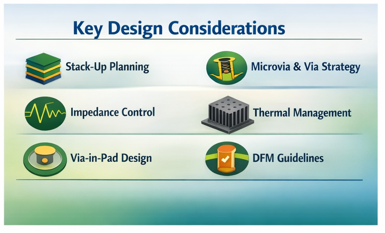
- Signal Integrity Management: Medical devices frequently process low-amplitude signals from sensors or electrodes, requiring careful impedance control, proper grounding schemes, and separation of analog and digital circuits to prevent signal degradation. High-quality medical PCB designs incorporate techniques like ground planes, matched trace lengths, and differential signaling to maintain signal fidelity.
- Power Distribution Integrity: Medical devices often incorporate multiple voltage domains and sensitive analog circuits, necessitating robust power distribution networks with adequate decoupling, voltage regulation, and protection against power-related disturbances. Proper power integrity design prevents malfunctions in critical care equipment.
- Thermal Management Considerations: Effective heat dissipation through thermal vias, appropriate copper weighting, and sometimes metal cores ensures reliable operation particularly in compact portable devices where component density creates thermal challenges.
- Manufacturing-Driven Design (DFM): Designing for manufacturability involves selecting standard components, maintaining appropriate clearances, and considering assembly processes to ensure reliable manufacturing while controlling costs. DFM principles become especially critical in medical devices where quality consistency is paramount.
- Testability Integration (DFT): Incorporating test points, boundary scan capabilities, and built-in self-test features facilitates verification during manufacturing and throughout the device lifecycle, supporting maintenance and troubleshooting in clinical settings.
Regulatory and Safety Considerations
Table: Key Medical PCB Design Standards and Their Implications
| Standard/Regulation | Scope | Design Implications |
|---|---|---|
| ISO 13485 | QMS for medical devices | Documentation, design control, traceability |
| IEC 60601-1 | Safety for medical electrical equipment | Creepage/clearance, isolation, protective earth |
| ISO 14971 | Risk management for medical devices | Risk analysis, risk control, residual risk review |
| FDA 21 CFR Part 820 | US medical quality system regulation | Design validation, change control, DHF records |
| IEC 61010-1 | Safety for measurement and lab equipment | Added safety for lab and diagnostic devices |
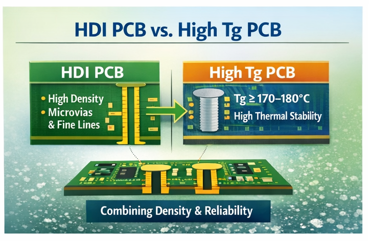
Advanced medical PCB design often relies on HDI structures for miniaturization, rigid-flex architectures for space-constrained layouts, and embedded components to enhance performance and save board area. As devices grow more complex, strong EMC design—including proper filtering, shielding, and controlled layout—becomes essential to ensure stable operation in noisy clinical environments. These advanced techniques help medical PCBs achieve the reliability, compliance, and long-term stability required for clinical use.
Why Do Compact Medical Products Rely on Reliable HDI PCB Fabricators for Compact Medical Devices?
Compact medical products rely on HDI PCBs because they enable extreme miniaturization, tighter layouts, and higher functionality in limited space. HDI technology offers finer traces, smaller microvias, and dense interconnects that standard PCBs cannot support, making it ideal for wearables, implantables, and portable diagnostic devices.
Specialized HDI fabricators are essential because medical-grade miniaturization requires strict process control, high precision, and cleanroom environments. Their capability to achieve 3-mil lines and <0.15 mm microvias allows complex circuitry to fit into ultra-small devices used in minimally invasive tools and continuous monitoring systems.
Advantages of HDI Technology in Medical Devices
- Enhanced Signal Integrity: Shorter routing and dense interconnects reduce delays and interference, improving performance in high-speed imaging and monitoring systems.
- Improved Thermal Management: Thermal vias and optimized copper help dissipate heat in compact layouts, extending device life—especially for implantables.
- Higher Reliability: Microvias eliminate stress points found in through-hole vias, providing better durability for wearable and motion-exposed devices.
- Design Flexibility: HDI supports mixed-signal integration (analog + digital + RF) on compact boards, enabling multifunctional medical device designs.
HDI Implementation Considerations for Medical Applications
| Capability Level | Typical Specifications | Medical Device Applications |
| Standard HDI | 4 mil lines/spaces, 0.2 mm microvias | Patient monitors, portable diagnostics |
| Advanced HDI | 3 mil lines/spaces, 0.15 mm microvias | Surgical robotics, imaging, wearables |
| Ultra HDI | <2 mil lines/spaces, 0.1 mm microvias | Implantables, micro-invasive tools |
As medical devices move toward smaller, smarter, and more reliable designs, HDI PCB fabrication has become a foundational technology—making experienced HDI medical-grade manufacturers indispensable.

When Should Engineers Choose the Best Rigid-Flex PCB Assembly Services for Medical Devices?
Engineers should choose rigid-flex PCB assembly when medical devices require high reliability in tight spaces, especially where repeated bending, motion, or 3D packaging is unavoidable. The technology combines rigid-board stability with flexible circuitry, reducing connectors and cables, lowering failure risks, and enabling smaller, lighter medical products.
Rigid-flex PCBs are ideal for devices that undergo constant movement, must fit into compact structures, or demand higher durability than conventional rigid boards can provide. Although initial manufacturing costs may be higher, the gains in reliability, size reduction, and long-term stability often justify the investment in medical applications.
Medical Applications Best Served by Rigid-Flex PCB Technology
- Surgical Robotics and Instruments: Supports complex mechanical layouts, maintains clean signals, and eliminates connector-related failures in critical surgical equipment.
- Portable and Wearable Medical Devices: Handles daily flexing and improves comfort and durability in patches, glucose monitors, and inhalation devices.
- Miniaturized Implantable Devices: Enables ultra-compact, long-life designs for neurostimulators, pacemakers, and drug delivery implants.
- Medical Imaging Systems: Ensures stable high-frequency signal paths and withstands repeated motion and sterilization in ultrasound and endoscopic probes.
Key Considerations in Rigid-Flex PCB Selection
| Decision Factor | Considerations | Impact on Medical Device Design |
|---|---|---|
| Mechanical Requirements | Flex cycles, bend radius, tight space | Determines materials, stackup, reinforcement |
| Signal Integrity Needs | High-speed digital, sensitive analog, RF | Affects layer order, shielding, impedance control |
| Environmental Factors | Sterilization, temperature, humidity | Influences materials, coatings, and testing |
| Regulatory Compliance | Biocompatibility, certifications | Drives material approval, documentation, validation |
| Manufacturing Considerations | Volume, yield, cost targets | Impacts design rules, panelization, and inspection strategy |
Successful rigid-flex medical PCB development requires early collaboration with experienced manufacturers to optimize materials, stackups, and flex regions. Designs must undergo mechanical reliability testing beyond normal use conditions, ensuring resilience during bending and repeated sterilization cycles. Considering sterilization compatibility—such as autoclave, gamma, or chemical methods—is essential to ensure long-term stability in clinical environments.
As medical devices move toward smaller, more integrated, and more mobile formats, rigid-flex PCBs provide the durability and compactness needed to support next-generation healthcare innovations. Selecting partners with proven medical expertise ensures performance, safety, and manufacturability.
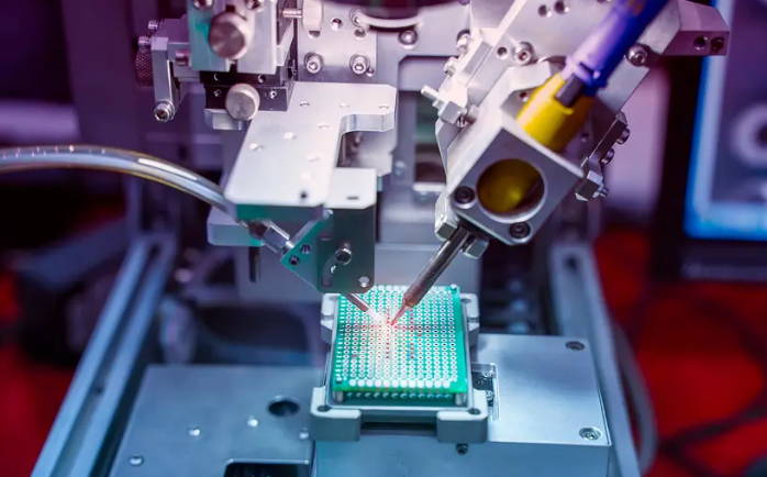
How Does Medical Device PCB Manufacturing Maintain Cleanliness and Compliance?
Medical device PCB manufacturing ensures cleanliness and compliance by combining controlled environments, strict process control, and complete documentation. ISO-rated cleanrooms, validated workflows, and rigorous quality systems ensure PCBs meet the reliability and safety levels required for clinical use. These measures prevent contamination, maintain traceability, and ensure every production step aligns with medical regulatory standards.
Clean manufacturing begins with ISO Class 7 (or better) cleanrooms that control airborne particles and prevent defects such as solder issues or electrical leakage. This controlled environment supports consistent performance in life-critical medical applications.
Key Elements of Medical PCB Manufacturing Compliance
- Material Traceability Systems: Full material-to-process tracking ensures quick investigation and recall capability when quality issues arise.
- Process Validation Protocols: All key processes—etching, drilling, solder mask, finishing—are validated to maintain stable, repeatable results.
- Comprehensive Documentation Practices: Detailed records of design, manufacturing steps, inspections, and non-conformances support audits and regulatory submissions.
- Sterilization Compatibility: Materials and finishes must tolerate autoclave, gamma, EO, or chemical sterilization without degradation.
- Biocompatibility Assurance: ISO 10993-approved materials ensure no harmful substances migrate from the PCB during device use.
Cleanroom Manufacturing Protocols for Medical PCBs
| Cleanroom Class | Max Particles / m³ (≥0.5μm) | Typical Medical PCB Applications |
|---|---|---|
| ISO Class 8 | 3,520,000 | Large equipment, non-critical monitors |
| ISO Class 7 | 352,000 | Implantables, surgical tools, diagnostics |
| ISO Class 6 | 35,200 | High-reliability implantables, surgical robotics |
| ISO Class 5 | 3,520 | Nanoscale devices, advanced biosensors |
Compliance relies on ISO 13485-certified quality systems governing documentation, training, calibration, CAPA, and management oversight. Leading manufacturers stay aligned with global regulations such as FDA, MDR/IVDR, and regional standards to ensure market readiness.
As medical electronics become more advanced, processes must evolve—HDI structures, embedded components, and new materials require ongoing validation and higher cleanliness standards. With robust controls and continuous improvement, medical PCB manufacturers deliver the reliability essential for devices where patient safety depends on consistent performance.
Why Do Imaging and Wireless Systems Need Top RF Microwave PCB Board Fabricators for Medical Devices?
Imaging and wireless medical systems require top RF microwave PCB fabricators because high-frequency signals demand far tighter control than standard PCBs can provide. At GHz-level operation, signal loss, impedance drift, and material inconsistencies directly affect diagnostic accuracy and wireless reliability. Specialized RF fabricators offer the materials expertise, manufacturing precision, and transmission-line control needed to maintain stable performance in demanding clinical environments.
In RF medical PCBs, signals behave like electromagnetic waves rather than simple currents. This requires precise impedance matching, stable dielectric properties, and low-loss routing to ensure clean signals for MRI, wireless monitors, therapeutic microwave systems, and implantable communications.
Key RF PCB Considerations for Medical Applications
- Controlled Dielectric Properties: Use materials with stable Dk/Df (e.g., Rogers, PTFE) to maintain predictable high-frequency performance.
- Precise Impedance Control: Tight impedance tolerance (±5% or better) prevents signal reflections that degrade diagnostic measurements.
- Signal Loss Minimization: Low-loss substrates, smooth copper, and proper finishing reduce attenuation in antennas and sensitive receivers.
- Electromagnetic Compatibility: Shielding, filtering, and careful layout prevent RF interference, ensuring device safety and regulatory compliance.
Medical Applications of RF Microwave PCBs
| Medical Application | Frequency Range | Key PCB Requirements |
|---|---|---|
| Wireless Patient Monitoring | 2.4 / 5 GHz | Impedance control, low power, antenna integration |
| Medical Imaging Systems | 10 MHz – several GHz | Low noise, high stability, clean signal paths |
| Therapeutic Microwave | 900 MHz – 2.45 GHz | Power handling, heat control, high reliability |
| RF Ablation Systems | 200 – 500 kHz | High current, thermal management, precise control |
| Wireless Implantables | 402 – 405 MHz (MICS band) | Miniaturization, biocompatibility, power efficiency |
As medical devices adopt more wireless and high-frequency functions—Bluetooth, Wi-Fi, cellular, and implantable RF links—RF PCB expertise becomes essential. Reliable performance requires precise etching, material selection, antenna tuning, and strong EMC design.
Choosing experienced RF microwave PCB fabricators ensures proper substrate selection, tighter manufacturing tolerances, and stable performance across varying clinical environments. These partners understand both high-frequency design challenges and the reliability expectations of medical applications, enabling safer and more connected healthcare technologies.
What Drives Medical Device PCB Price From Prototype to Volume Production?
Medical device PCB pricing changes significantly from prototype to mass production because each stage requires different materials, process controls, and regulatory commitments. Early prototypes cost more due to setup fees, engineering time, and low volumes. As production scales, per-unit costs drop, but additional medical-grade testing and regulatory requirements continue to influence overall pricing.
Medical PCBs face unique cost pressures because they must meet strict reliability, traceability, and compliance standards. These demands elevate material selection, process control, and quality assurance expectations beyond those of commercial electronics, shaping the full cost structure throughout the product lifecycle.
Key Cost Drivers in Medical PCB Pricing
- Regulatory Compliance Costs: Medical-grade documentation, testing, and quality system maintenance add fixed costs that remain throughout production.
- Material Selection Impact: Premium materials for RF, thermal stability, or biocompatibility cost 20–300% more than standard FR-4.
- Testing and Quality Assurance: Extensive electrical, environmental, and burn-in tests increase costs, especially as volumes grow.
- Yield Considerations: Near-zero defect requirements necessitate tighter process control, slower production speeds, and more advanced equipment.
Medical PCB Cost Progression Factors
| Cost Factor | Prototype Phase | Pilot Production | Volume Manufacturing |
|---|---|---|---|
| Setup/NRE Costs | High (20–40% of total) | Moderate (10–20%) | Low (5–10%) |
| Material Costs | High (premium materials) | Balanced for cost/performance | Reduced with volume pricing |
| Labor Content | High (engineering-heavy) | Moderate (process refinement) | Low (automation) |
| Testing Costs | High (full validation) | High (process validation) | Moderate (sampling-based) |
| Regulatory Costs | High (initial compliance) | Moderate (documentation growth) | Moderate (ongoing compliance) |
Cost efficiency improves when companies apply DFM early, select components strategically, and partner with manufacturers who support engineering collaboration. As production moves from prototype to volume, secure supply chains and value engineering help reduce long-term costs without affecting performance or regulatory compliance.
Understanding these cost drivers helps medical device teams plan budgets accurately and balance innovation with manufacturability, ensuring financially sustainable development across the full product lifecycle.
How to Select Medical Device PCB Manufacturers That Meet Medical-Grade Standards?
Selecting medical-grade PCB manufacturers requires evaluating their technical capabilities, quality systems, and medical industry experience. Because PCB reliability affects patient safety and regulatory approval, manufacturers must demonstrate proven compliance, strong process control, and medical-focused engineering support. The goal is to find partners who can meet immediate technical needs while supporting long-term product lifecycle requirements.
The selection process begins with confirming medical-relevant certifications. ISO 13485 is essential, proving adherence to medical device quality systems. Complementary certifications such as ISO 9001, ISO 14001, and experience with IEC 60601-1 further validate a manufacturer’s ability to support healthcare applications.
Key Selection Criteria for Medical PCB Manufacturers
- Medical Industry Experience: Manufacturers with medical experience understand regulatory expectations, documentation flow, and reliability requirements, reducing development risks and improving approval outcomes.
- Technical Capabilities Alignment: Layer count, density, HDI, rigid-flex, RF capability, and material expertise must match device requirements to ensure performance and manufacturability.
- Quality System Robustness: Strong systems for SPC, traceability, testing, and change control ensure consistent quality across prototype and mass production stages.
- Supply Chain Stability: Reliable material sourcing, component continuity, and obsolescence strategies are essential for long-life medical devices.
Medical PCB Manufacturer Evaluation Framework
| Assessment Category | Key Evaluation Factors | Medical-Specific Considerations |
|---|---|---|
| Quality & Compliance | ISO 13485, FDA audit history, documentation discipline | Strong change control, regulatory-ready documentation |
| Technical Capabilities | Layer count, HDI, rigid-flex, RF, materials expertise | Experience with similar devices; DFM for medical reliability |
| Manufacturing Capacity | Equipment, cleanliness, volume capability | Cleanroom controls, contamination prevention, medical volume handling |
| Supply Chain Management | Component sourcing, traceability, obsolescence planning | Medical-grade materials, biocompatibility considerations |
| Business Factors | Financial stability, communication, cooperation style | Long-term partnership potential, rapid issue response |
Facility audits and customer references help verify real manufacturing capability rather than claimed experience. Beyond certifications, effective communication and engineering collaboration are essential because medical devices require iterative refinement and strict documentation. Manufacturers with long-term stability and commitment to the medical market provide better lifecycle support, from prototypes to large-scale production.
By using a structured evaluation approach combining technical, quality, and partnership factors, medical device companies can select PCB manufacturers capable of delivering reliable, compliant, and long-term medical-grade performance.
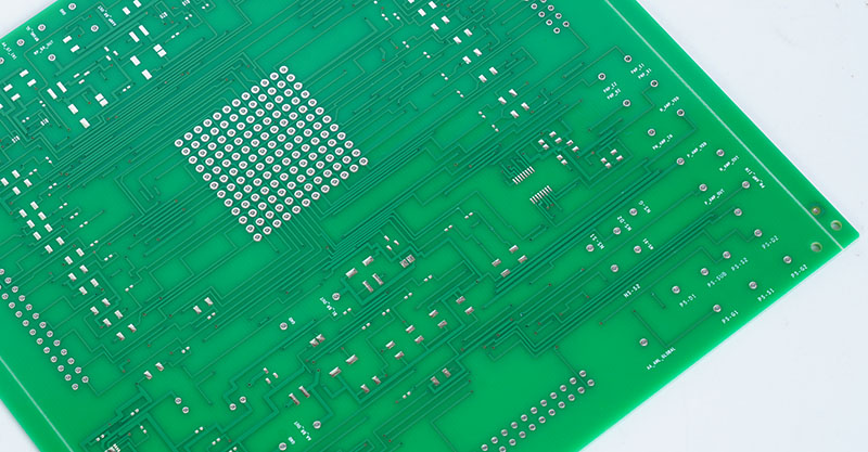
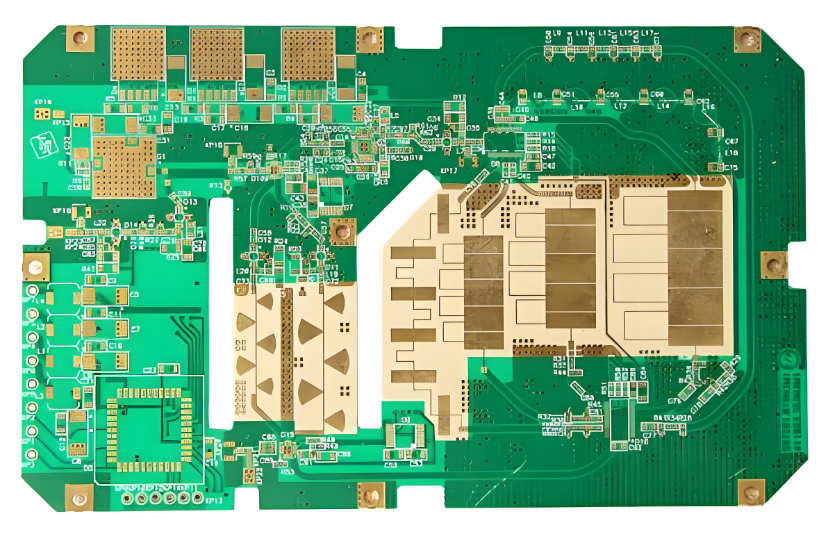
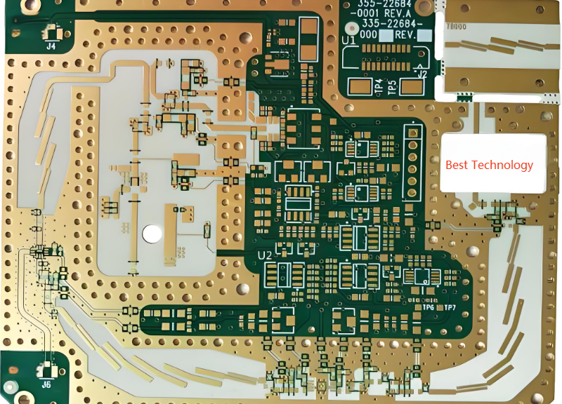
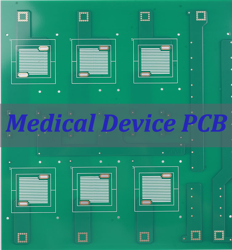
Case of Medical PCB Board Fabrication by EBest Circuit (Best Technology)
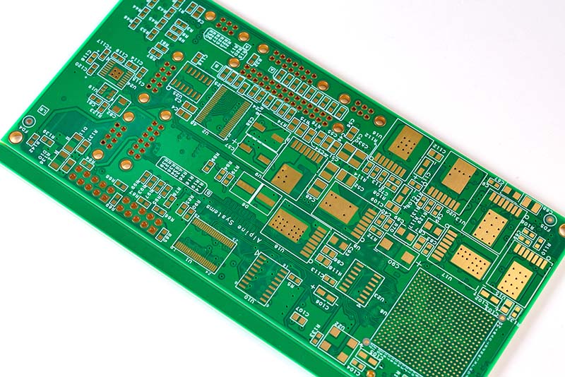
This PCB’s combination of robust construction, controlled impedance, and moderate layer count makes it well-suited for a variety of non-implantable but critical medical devices where reliability and signal integrity are paramount.
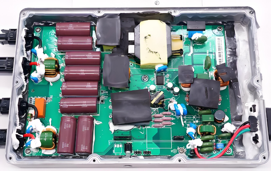
- Portable Patient Monitor: This PCB could serve as the main control board in a compact vital signs monitor used in ambulances, clinics, or for in-home care. It would be responsible for processing signals from sensors measuring parameters like blood pressure, blood oxygen saturation (SpO₂), and electrocardiogram (ECG). The controlled impedance on layers 1, 3, and 6 is critical for ensuring the accurate transmission of these analog sensor signals without degradation, minimizing noise for a clear reading. The board’s 1.6mm thickness and FR4 TG150 material provide the necessary durability for portable use.
- Laboratory Diagnostic Equipment: In automated lab analyzers used for processing blood or fluid samples, this board could act as an interface and control module. It would manage motor controllers for moving samples, read data from precision optical sensors, and handle communication with a central computer. The six layers allow for a clear separation of power and signal planes, reducing the risk of electrical noise interfering with sensitive measurements. The ENIG (Electroless Nickel Immersion Gold) surface finish ensures a flat, reliable surface for the soldering of fine-pitch components, which is essential for the long-term operational reliability of equipment that runs frequent tests.
- Advanced Therapeutic Device Control System: This PCB is ideal for the main logic board in devices like smart infusion pumps or non-invasive nerve stimulators. In an infusion pump, it would precisely control the stepper motor responsible for drug delivery while managing user interface commands and safety alarms. The Tg150 glass transition temperature indicates a good resistance to thermal stress, which is important for devices that may operate continuously. The specified impedance control helps maintain signal timing for the digital circuits that execute treatment protocols accurately.
PCB Board Parameters
Here is a concise summary of the board’s key specifications in the requested format.
- Number of Layers: 6
- Base Material: FR4 TG150
- Copper Weight (Finished): 1oz
- Board Thickness: 1.6mm
- Solder Mask Color: Green
- Silkscreen Color: White
- Surface Finish: ENIG (Electroless Nickel Immersion Gold), 1U” (approx. 0.025 – 0.03µm Gold)
- Bow and Twist: < 0.75%
- Controlled Impedance: 100ohm Differential on Layers 1, 3, and 6
- Fabrication Standard: IPC CLASS 2
This PCB’s parameters indicate a design focused on signal integrity (controlled impedance), good mechanical stability (Tg150, bow and twist specification), and solderability (ENIG finish), making it a solid choice for the demanding healthcare environment.
Why Choose EBest Circuit (Best Technology) as Your Reliable Medical Devices PCB Assembly Factory?
Selecting EBest Circuit (Best Technology) as your medical devices PCB assembly partner provides access to comprehensive expertise specifically tailored to the unique requirements of healthcare technology manufacturing. Our established track record spanning over two decades in medical PCB assembly demonstrates consistent commitment to quality, innovation, and customer success in the demanding medical device market.
EBest Circuit (Best Technology)’s Medical PCB Assembly Advantages
- Comprehensive Medical Experience: With over 19 years specializing in medical device PCB assembly, we have developed deep understanding of healthcare technology requirements including regulatory pathways, clinical use environments, and reliability expectations. This experience enables more effective design guidance, smoother regulatory submissions, and fewer manufacturing issues.
- Advanced Technical Capabilities: Our manufacturing facilities incorporate state-of-the-art equipment for high-density interconnect (HDI) PCBs, rigid-flex assemblies, and RF/microwave boards appropriate for advanced medical devices. These capabilities include precision component placement, controlled impedance machining, and automated optical inspection systems that ensure manufacturing consistency.
- Accelerated Prototyping Services: We offer rapid prototyping services with turnaround times as quick as 48 hours for initial prototypes, significantly compressing medical device development cycles without compromising quality or compliance. This accelerated prototyping capability enables iterative design refinement that enhances final product performance and manufacturability.
- Supply Chain Integration: Our established relationships with component manufacturers and distributors provide reliable access to medical-grade components, including management of obsolescence and supply disruptions that can impact medical device production. This supply chain stability ensures consistent production for medical devices with potentially multi-year lifecycles.
- Quality Control Assurance: We maintain a medical-grade quality system that includes full IQ, DQ, and PQ validation, giving customers traceable documentation for equipment installation, design conformity, and performance qualification. Each medical PCB is verified through AOI, X-ray, ICT/FCT, and reliability checks, with complete material and process traceability to support ISO 13485, FDA, and MDR/IVDR compliance. This consolidated quality framework ensures stable yields, consistent performance, and audit-ready records for medical device manufacturers.
We assign dedicated engineering teams to medical device projects, ensuring continuity and deep understanding of each device’s specific requirements and challenges. Our comprehensive service model provides single-point responsibility from design support through component sourcing, PCB fabrication, assembly, testing, and logistics. Our combination of technical expertise, quality systems, regulatory knowledge, and partnership approach provides the foundation for reliable, compliant medical devices that deliver consistent performance in clinical applications. Pls feel free to contact us at sales@bestpcbs.com to discuss how our medical PCB assembly capabilities can support your healthcare technology initiatives with the quality, reliability, and expertise demanded by medical applications.

In summary, medical Device PCBs represent the critical foundation enabling modern healthcare technology, serving as the sophisticated electronic backbone that transforms clinical concepts into reliable medical devices that improve patient outcomes. Technical specialization in areas like HDI technology, rigid-flex designs, and RF microwave capabilities enables the advanced functionality required by modern medical devices.
At EBest Circuit (Best Technology), we have built our medical PCB capabilities around these fundamental principles, combining technical excellence with medical-specific expertise and accelerated prototyping services that support innovation throughout the medical device lifecycle. Our comprehensive approach to medical PCB solutions encompasses design support, manufacturing excellence, quality systems, and regulatory expertise tailored specifically to healthcare technology requirements.