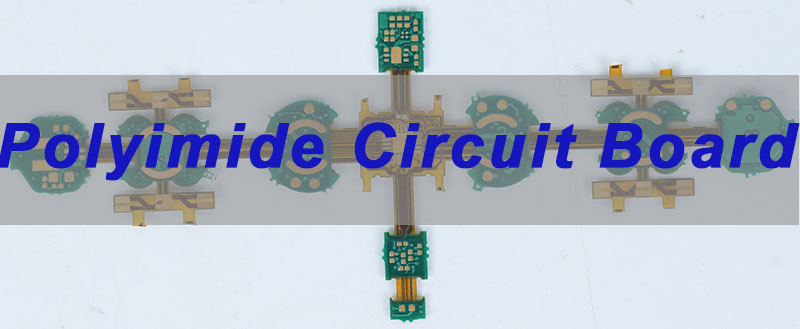
Polyimide Circuit Board materials represent the pinnacle of performance for electronics that must endure extreme environments and demanding mechanical stress. This article explores the unique properties, applications, and selection criteria for polyimide PCBs, providing engineers with the insights needed to leverage their full potential for reliable, next-generation devices.
Developing cutting-edge electronics for aerospace, medical, or advanced automotive applications often hits a wall when conventional materials like FR4 reach their limits. Where do these pain points typically emerge?
- High material and processing costs strain project budgets, making it difficult to justify the switch to high-performance substrates without clear ROI.
- Inadequate thermal management leads to premature device failure, delamination, or performance drift in high-temperature applications.
- Mechanical stress and fatigue cause cracks in conductors or the substrate itself, especially in dynamic flexing or vibration-prone environments.
- Complex assembly and soldering issues arise due to polyimide’s different thermal expansion and surface properties, affecting manufacturing yield.
- Long lead times and slow prototyping delay critical validation phases, slowing down time-to-market for innovative products.
The solution lies in expert engineering support and controlled processes that transform the inherent properties of polyimide circuit board material into reliable, producible hardware.
- Cost-Effective Design Optimization: Our engineering team optimizes panel utilization, layer stack-ups, and material selection to control costs without compromising the core polyimide circuit board material properties needed for your application.
- Proven Thermal Management Strategies: We employ precise thermal simulation and process controls to ensure the thermal stability of your polyimide board, preventing delamination and ensuring long-term reliability.
- Mechanical Reliability Engineering: By optimizing bend radii, stiffener placement, and conductor design, we mitigate mechanical stress to prevent cracking and extend the lifecycle of your polyimide flex PCB.
- Assembly-Ready Process Controls: Our stringent process controls for surface finish, soldermask, and lamination ensure high yield during assembly, addressing common polyimide circuit board problems related to soldering.
- Rapid Prototyping Pipeline: We maintain dedicated capacity and material inventory for quick-turn polyimide circuit board prototypes, accelerating your design iteration and testing phases dramatically.
At EBest Circuit (Best Technology), we provide reliable polyimide circuit board solutions backed by 19 years of PCB manufacturing experience, serving medical, IoT, and industrial control customers. With aerospace AS9100D and medical ISO 13485 certifications, advanced fabrication capability, and MES-driven production lines, we combine material science expertise with strict process control to deliver high-performance and production-ready polyimide flex PCB designs. For your next polyimide flex PCB project, pls feel free to contact us at sales@bestpcbs.com.
What Is a Polyimide Circuit Board Material?
A polyimide circuit board material is a high-performance polymer laminate used as the insulating substrate in printed circuit boards. Renowned for its exceptional thermal, chemical, and mechanical stability, polyimide material serves as the backbone for electronics operating in extreme conditions where common materials like FR4 PCB board would fail. Unlike standard epoxy-based laminates, polyimide maintains its integrity across a vast temperature range.
The core value of this material lies in its molecular structure, which provides a unique set of properties essential for advanced applications.
- Exceptional Thermal Endurance: It has a high glass transition temperature (Tg), often exceeding 250°C, and can withstand continuous operating temperatures up to 260°C without degrading.
- Superior Mechanical Strength: Even in thin gauges, polyimide films offer high tensile strength and modulus, making them ideal for flexible PCB material.
- Excellent Chemical Resistance: It is highly resistant to solvents, acids, and oils, which is crucial for harsh environments like automotive under-the-hood applications.
- Inherent Flame Retardancy: Most polyimide materials are naturally flame-retardant (UL94 V-0) without requiring halogenated additives.
- Stable Dielectric Properties: Its electrical insulation properties remain consistent across a wide frequency and temperature range.
In summary, what is polyimide material in the context of electronics? It is the engineered answer for reliability under stress, forming the critical foundation for circuits that must be as durable as they are functional.
What Are the Unique Advantages of a Polyimide Circuit Board for High-Reliability Applications?
Polyimide circuit boards are not just an alternative to standard PCBs; they are a necessity for applications where failure is not an option. Their advantages directly address the stringent requirements of mission-critical systems in aerospace, military, medical implants, and downhole drilling equipment.
The primary benefits stem from the material’s ability to perform consistently under extreme duress.
- Unmatched Thermal Stability: Devices experience minimal expansion, contraction, or warping during thermal cycling, preventing solder joint failure and maintaining signal integrity. This is a key differentiator in the polyimide vs FR4 PCB debate.
- Outstanding Durability & Flex Life: For dynamic flexing applications, polyimide flex PCB constructions can endure millions of bend cycles without failure, which is essential for moving parts in robotics or foldable electronics.
- High Radiation and Chemical Resistance: Polyimide withstands exposure to gamma radiation, UV light, and corrosive chemicals much better than most materials circuit boards are made of, ensuring longevity in space or industrial settings.
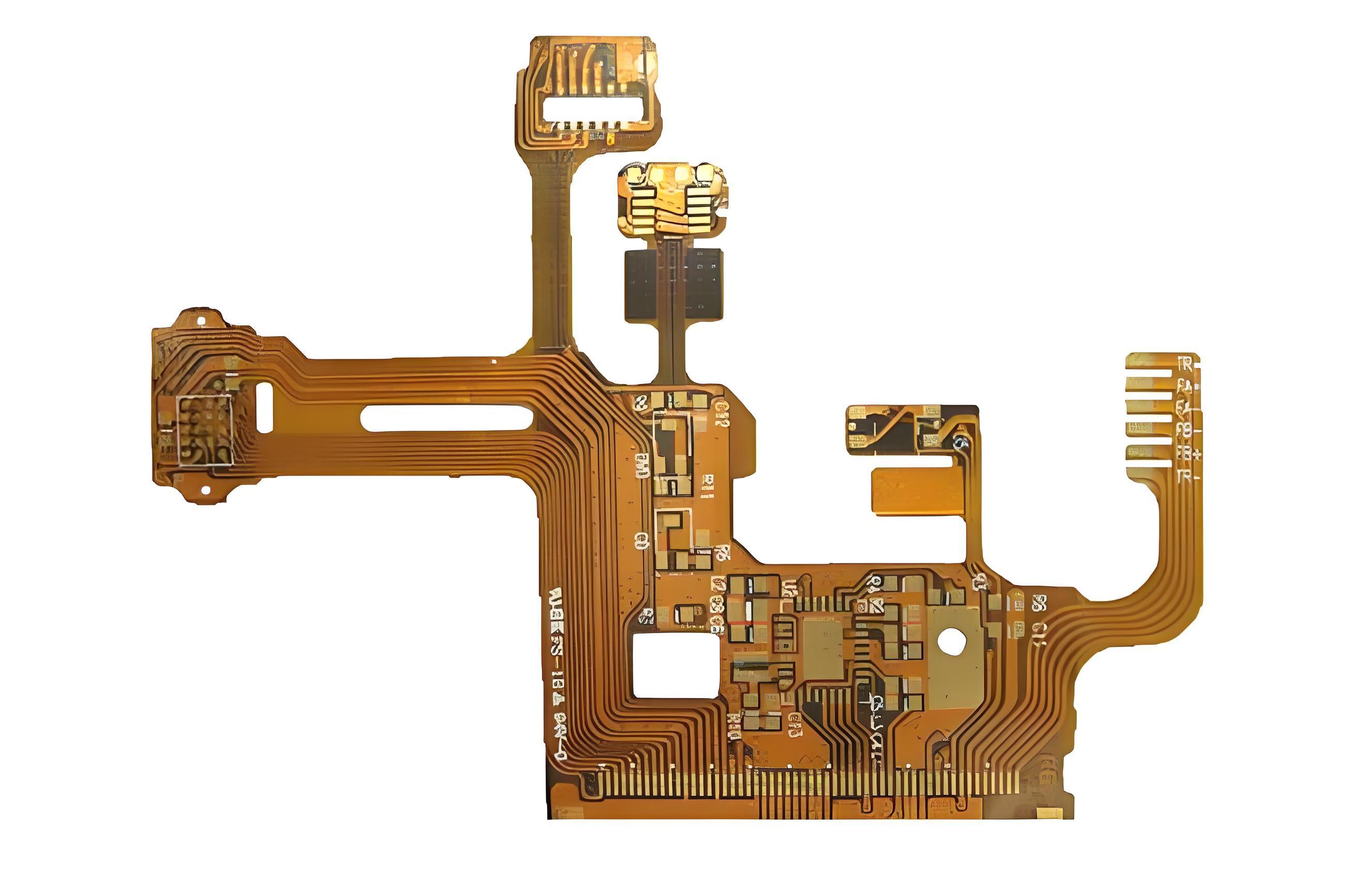
- Miniaturization Enabler: Its strength at thin profiles allows for dense, lightweight, and compact packaging of complex circuitry.
- Reliable Performance in Vacuum: It has low outgassing properties, making it safe for use in vacuum environments like satellites and scientific instruments.
Ultimately, the unique advantages of a polyimide printed circuit board translate into unparalleled reliability. They enable engineers to push the boundaries of technology, designing electronics that are more powerful, compact, and resilient than ever before.
Understanding Polyimide Circuit Board Material and How It Differs From Conventional Laminates
To choose the right substrate, it’s crucial to understand how polyimide circuit board material fundamentally differs from conventional laminates like FR4. While both serve as insulating layers, their composition, performance boundaries, and ideal use cases are worlds apart. The choice often boils down to the operational envelope of the final product.
The differences are most apparent when comparing key characteristics side-by-side.
| Feature | Polyimide Laminate | Conventional FR4 Laminate |
|---|---|---|
| Base Resin | Polyimide polymer | Epoxy (typically brominated for FR) |
| Glass Transition Temp (Tg) | Very High (>250°C) | Mid-Range (130°C – 180°C) |
| Max Continuous Operating Temp | ~260°C | ~130°C – 150°C |
| Flexural Endurance | Excellent (for flex grades) | Poor (rigid, brittle) |
| Chemical Resistance | Excellent | Good |
| Moisture Absorption | Low | Moderate to High |
| Cost | Higher | Lower |
This comparison clarifies the polyimide vs FR4 decision. FR4 PCB is the economical, high-volume workhorse for standard commercial electronics. In contrast, polyimide PCB is the specialized, high-performance solution for extreme thermal, mechanical, or environmental challenges. Other high-end materials like PTFE PCB (excellent for RF) may compete in specific niches, but polyimide remains the champion for combined thermal-mechanical performance.
How Polyimide Circuit Board Material Properties Influence Thermal Stability and Mechanical Durability?
The legendary thermal stability and mechanical durability of polyimide PCBs are not accidental; they are the direct result of specific, engineered polyimide circuit board material properties. These properties are intrinsically linked at the molecular level, creating a synergistic effect that defines the material’s performance ceiling.
The key properties driving this performance can be broken down as follows:
- High Glass Transition Temperature (Tg): This is the temperature at which the polymer transitions from a hard, glassy state to a soft, rubbery one. Polyimide’s exceptionally high Tg (>250°C) means it retains its rigidity and dimensional stability at soldering temperatures and in high-heat operating environments, preventing warping and delamination.
- Low Coefficient of Thermal Expansion (CTE): Polyimide’s CTE is closely matched to copper. This minimizes stress at the copper-substrate interface during temperature swings, dramatically reducing the risk of plated through-hole (PTH) barrel cracking and conductor delamination—a common polyimide circuit board problem if not properly managed.
- Aromatic Heterocyclic Structure: The rigid, ring-based molecular chains create a high modulus (stiffness) and tensile strength, even in thin-film form. This provides the mechanical backbone for polyimide flex PCB applications, allowing repeated bending without permanent deformation or cracking.
- Strong Molecular Bonds: The covalent bonds within the polyimide chain are highly resistant to thermal and chemical breakdown, contributing to its long-term stability under stress and its excellent dielectric strength.
In essence, the polyimide PCB material properties form a virtuous cycle: thermal stability prevents mechanical stress from temperature changes, while mechanical strength maintains structural integrity under thermal load. Understanding this interplay is essential for designing reliable hardware that leverages the full potential of this advanced material.
Comparing Polyimide vs FR4 to Determine the Right Material for Demanding Electronics
The decision between polyimide vs FR4 is a fundamental one in PCB design, impacting cost, performance, and manufacturability. There is no universally “better” material; the right choice depends entirely on the demands of the specific application. A clear comparison illuminates the trade-offs.
The selection criteria hinge on several environmental and operational factors, as summarized below:
| Decision Factor | Choose Polyimide PCB When… | Choose FR4 PCB Board When… |
|---|---|---|
| Operating Temperature | Exceeds 150°C or involves intense thermal cycling. | Remains below 130°C-150°C consistently. |
| Mechanical Environment | Dynamic flexing, vibration, or space/weight constraints are critical. | The board is static within a rigid enclosure. |
| Chemical/Radiation Exposure | The environment is harsh (oils, fuels, solvents, radiation). | The environment is benign (standard indoor use). |
| Electrical Performance | Stable dielectric constant (Dk) over a wide temp/frequency range is needed. | Standard electrical properties at room temperature are sufficient. |
| Project Budget | Performance and reliability justify a higher unit cost. | Cost minimization for high-volume production is the priority. |
For instance, a polyimide vs FR4 PCB analysis for an automotive engine control unit (ECU) would heavily favor polyimide due to under-the-hood temperatures. Conversely, a consumer television’s mainboard would optimally use cost-effective FR4 PCB. Understanding this polyimide vs FR4 matrix allows engineers to make data-driven material selections that align technical requirements with business objectives.
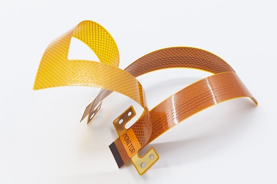
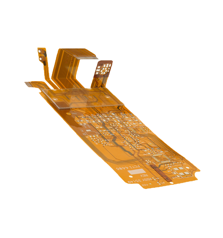
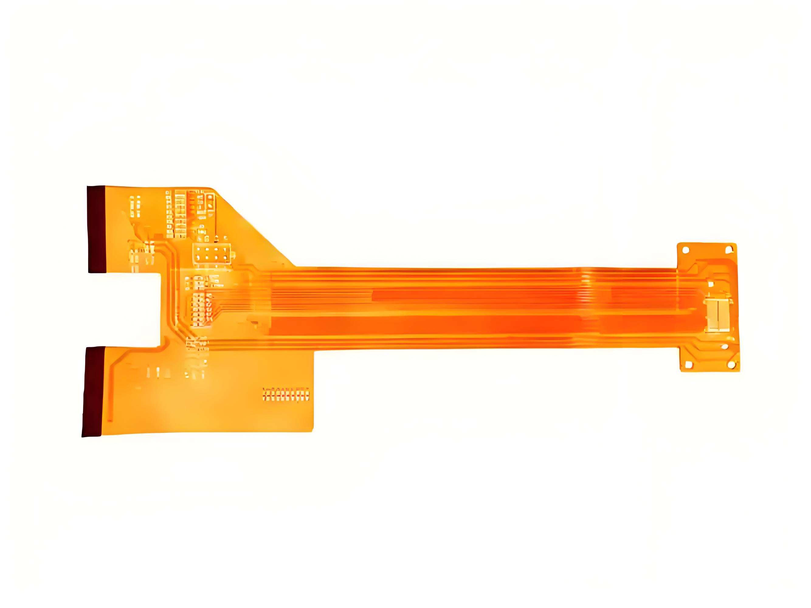
Why Polyimide Flex PCB Designs Are Essential for Wearables, Aerospace, and Miniaturized Devices?
Polyimide flex PCB designs are not merely convenient; they are enabling technologies that make modern miniaturized and robust electronics possible. Their unique combination of thinness, flexibility, and reliability solves geometric and environmental challenges that rigid boards cannot address.
The essential nature of these designs is evident across several cutting-edge industries:
- Wearable Medical Devices & Consumer Tech: They conform comfortably to the human body, endure constant movement, and enable ultra-lightweight designs for hearing aids, fitness monitors, and smart clothing.
- Aerospace & Avionics: In satellites and aircraft, polyimide flex PCBs save crucial weight and space. Their reliability under extreme thermal cycling (from -55°C to +125°C+), vacuum, and vibration is unmatched by other flexible PCB material options.
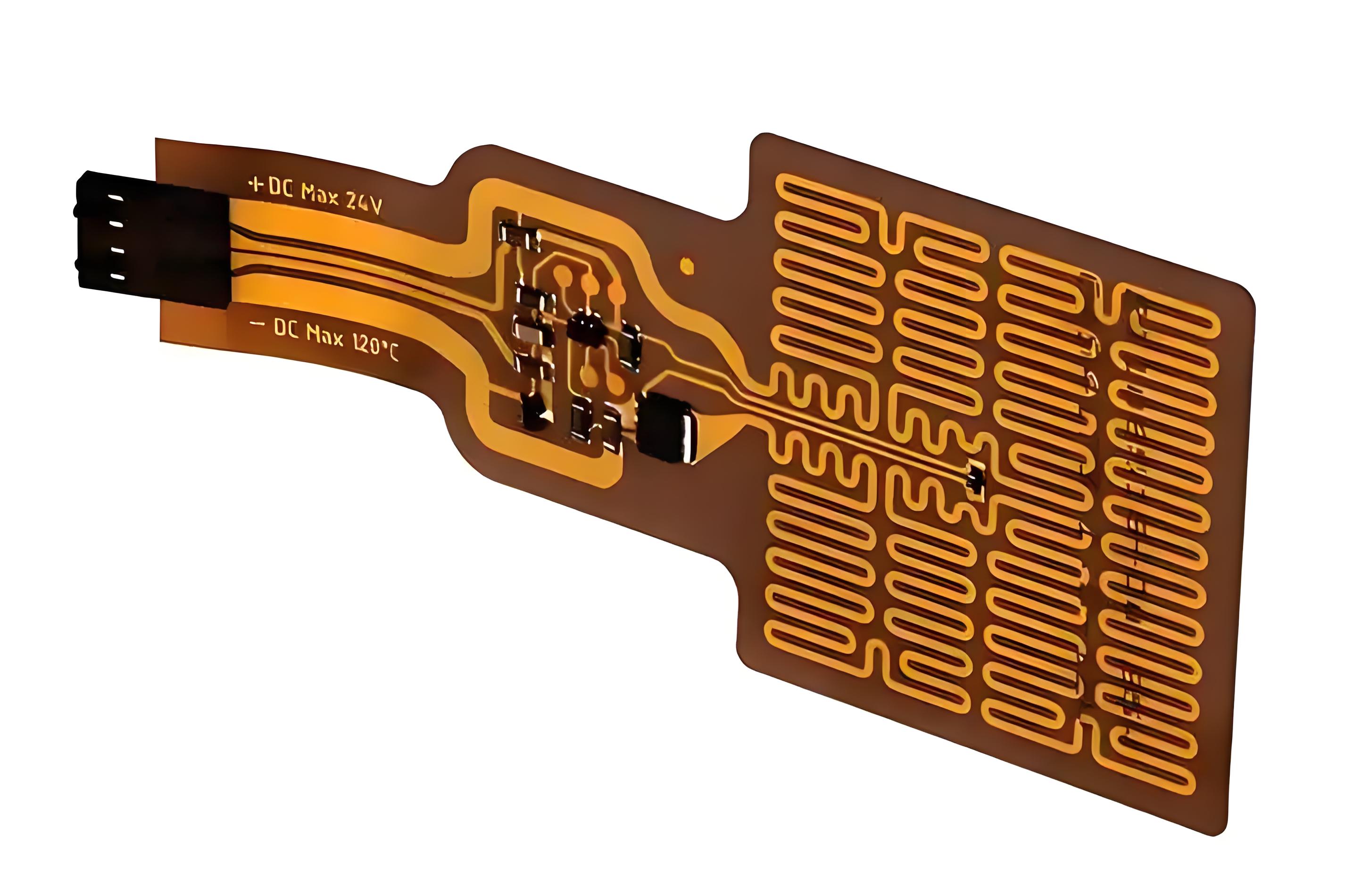
- Advanced Automotive Systems: They navigate the tight, hot, and moving spaces within vehicles, connecting sensors in doors, seats, and around the engine where rigid boards would fail.
- Miniaturized Electronics: They allow for innovative 3D packaging, folding, and stacking of circuitry in smartphones, cameras, and drones, maximizing functionality in minimal volume.
- High-Reliability Industrial: Used in robotic arms and moving machine parts, they provide a durable, dynamic interconnection that outlasts cables and connectors.
The move towards polyimide flex PCB solutions is driven by the need for devices that are smaller, lighter, more durable, and capable of operating in three dimensions. As polyimide PCB manufacturers advance their processes, these designs continue to push the boundaries of what’s electrically and mechanically possible.
What Polyimide Circuit Board Manufacturers Provide in Terms of Engineering Capability and Process Control?
Selecting among polyimide circuit board manufacturers is as critical as selecting the material itself. The high-performance potential of polyimide can only be realized through expert engineering and meticulous process control. A top-tier manufacturer provides a partnership that extends far beyond simple fabrication.
Key capabilities that distinguish leading polyimide PCB manufacturers include:
- Deep Material Science Expertise: Understanding the nuances of different polyimide grades (e.g., polyimide vs polyamide), adhesiveless vs. adhesive-based constructions, and their compatibility with various finishes is crucial.
- Advanced DFM (Design for Manufacturability) Analysis: Proactive engineering review to optimize designs for yield and reliability, advising on critical aspects like bend radii, stiffener placement, and coverlay openings.
- Precision Lamination Process Control: Consistent pressure, temperature, and vacuum cycles are vital to prevent voids, delamination, and to control the material properties of the final multilayer stack-up.
- Specialized Handling and Etching: Polyimide’s sensitivity to moisture and chemicals requires controlled environments and tailored etching processes to achieve fine features without damaging the substrate.
- Rigorous Testing and Inspection Protocols: Implementation of electrical testing, microsectioning, and thermal stress testing (e.g., solder float test) to validate the reliability promised by the polyimide PCB material data sheet.
In short, the best polyimide PCB manufacturers act as an extension of your engineering team. They translate your design intent into a physical product that reliably meets all specifications, navigating the complexities inherent in working with this premium material.
Key Findings in a Polyimide PCB Material Data Sheet and How to Interpret Thermal and Electrical Ratings
A polyimide PCB material data sheet is the blueprint for performance. Knowing how to interpret its key findings allows engineers to make accurate predictions about how a board will behave in the real world and to select the optimal grade for their application.
When reviewing a data sheet, focus on these critical sections:
- Glass Transition Temperature (Tg): This is the starting point. A higher Tg indicates better resistance to thermal deformation. For lead-free soldering (peak ~260°C), a Tg of 250°C+ is essential.
- Decomposition Temperature (Td): The temperature at which the material begins to chemically break down and lose mass (typically measured at 5% weight loss). A higher Td provides a greater safety margin above Tg.
- Coefficient of Thermal Expansion (CTE): Usually given in X, Y, and Z axes (e.g., CTE (Z-axis) < 3%). A lower, more isotropic CTE is vital for reliability in thermal cycling, especially for multilayer boards and plated through-holes.
- Dielectric Constant (Dk) and Dissipation Factor (Df): These govern signal speed and loss. Note their values at your operating frequency (e.g., 1 GHz or 10 GHz) and whether they are stable over your expected temperature range.
- Dielectric Strength: Expressed in kV/mm, this indicates the dielectric strength of polyimide PCB—its ability to withstand high voltages without breaking down. It’s crucial for high-power or high-voltage designs.
- Moisture Absorption: A lower percentage is always better, as absorbed moisture can affect Dk, cause popcorning during soldering, and reduce insulation resistance.
- Flexural Endurance & Tensile Strength: For flex applications, these numbers, often given for the base film, indicate how well the material will withstand bending and stretching.
Interpreting these ratings requires context. For example, a stable Dk over temperature might be more important than its absolute value for a precision RF circuit. Cross-referencing data sheet claims with your manufacturer’s process capabilities is the final step in ensuring your design’s success.
Common Polyimide Circuit Board Problems and How Engineers Mitigate Failure Risks in Production
Even with its superior properties, polyimide circuit boards are not immune to challenges. Awareness of common polyimide circuit board problems is the first step toward preventing them. Proactive design and collaboration with a skilled manufacturer are the best risk mitigation strategies.
Here are key issues and their engineering solutions:
- Problem: Plated Through-Hole (PTH) Cracking.
Cause: Mismatch in the Z-axis CTE between copper and polyimide during thermal cycling.
Mitigation: Use polyimide materials with a low Z-axis CTE (<3%). Implement optimal desmear and plating processes to ensure good copper adhesion in the hole barrel. - Problem: Delamination or Blistering.
Cause: Moisture absorption, contamination during lamination, or excessive thermal stress during assembly.
Mitigation: Pre-bake boards before assembly. Ensure cleanroom lamination processes. Specify materials with low moisture absorption and verify assembly profiles. - Problem: Dimensional Instability/Warpage.
Cause: Asymmetric layer stack-ups or unbalanced copper distribution creating internal stress. Mitigation: Follow symmetrical stack-up design rules. Work with the manufacturer on a balanced layup and controlled multi-stage lamination cycles. - Problem: Solder Mask Adhesion Failure.
Cause: The smooth, chemically resistant surface of polyimide can challenge adhesion.
Mitigation: Use polyimide-specific solder masks. Ensure proper surface preparation (e.g., plasma treatment) prior to mask application. Perform thorough adhesion testing. - Problem: “Orange Peel” or Surface Roughness.
Cause: Inconsistent etchback or desmear processes on multilayer boards.
Mitigation: Tightly control chemical process parameters, times, and concentrations. Perform regular microsection analysis to monitor inner-layer interconnect quality.
By anticipating these issues, engineers can design rules and manufacturers can calibrate processes to avoid them. This collaborative, knowledge-based approach is fundamental to achieving the reliable polyimide circuit board solutions promised by the material’s exceptional data sheet properties.
Polyimide Circuit Board materials are the foundation upon which the most durable and advanced electronic systems are built. This article has detailed their properties, applications, and selection process to empower your design decisions.
From understanding the critical polyimide PCB material properties to navigating the choice of polyimide vs FR4, success hinges on expert execution. At EBest Circuit (Best Technology), we specialize in transforming these high-performance materials into reliable, production-ready solutions. For a partnership that delivers both reliability and agility, pls feel free to contact us anytime at sales@bestpcbs.com.
FAQs
How Thick Is Polyimide PCB?
The thickness of a polyimide PCB varies widely based on application. Flexible single-layer boards can be as thin as 0.025 mm (1 mil) for the core polyimide film, with overall build-ups including copper and coverlay ranging from 0.05 mm to 0.2 mm. Rigid or rigid-flex multilayer boards using polyimide can range from 0.4 mm to over 3.0 mm, similar to standard PCB thicknesses but with much higher thermal performance.
What Is the Dielectric Strength of Polyimide PCB?
The dielectric strength of polyimide PCB material is exceptionally high, typically in the range of 200 to 300 kV/mm for the base film. This means it can withstand a very high voltage per unit thickness before electrical breakdown occurs. However, the actual breakdown voltage of a finished PCB assembly will be lower and depends on factors like conductor spacing, surface cleanliness, and the presence of solder mask.
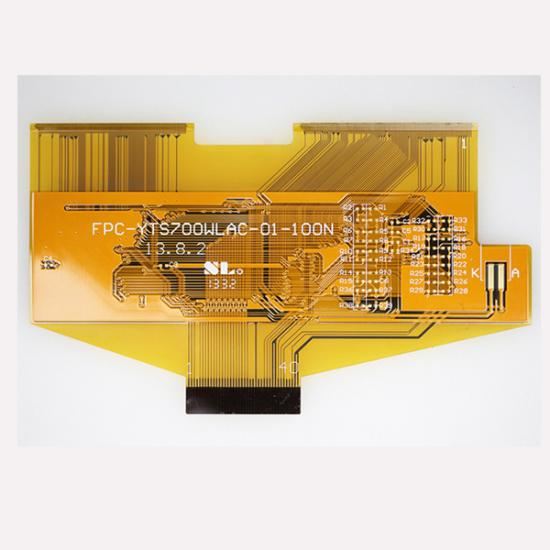
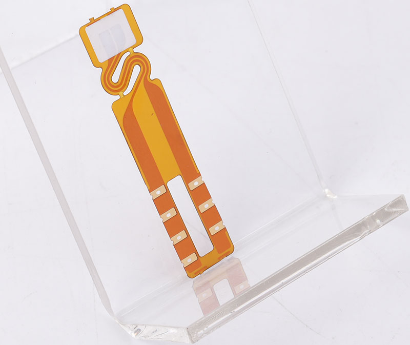
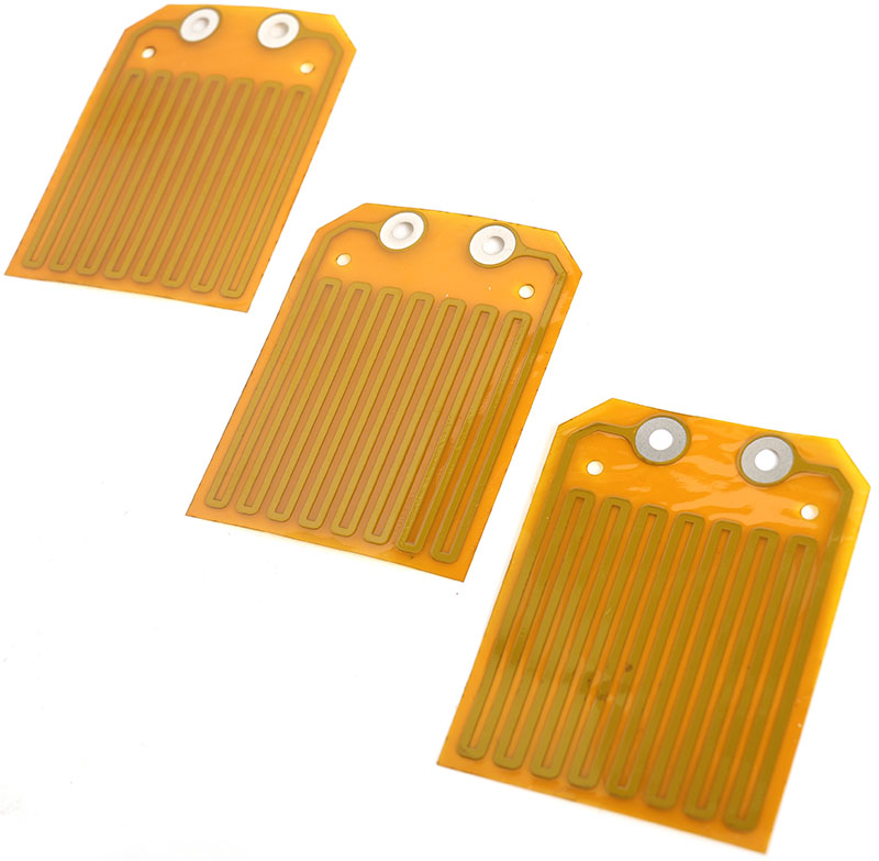
What Is the Color of Polyimide PCB?
The natural color of polyimide PCB base material is a distinctive amber or orange-gold. This is due to the chemistry of the polyimide polymer itself. The exposed substrate in “windows” of flexible circuits or the edges of boards will show this color. However, the surface is typically covered by copper, solder mask (which can be various colors, though green is common), and coverlay.