

PCB Robotics refers to the specialized field of designing and manufacturing printed circuit boards that serve as the central nervous system for robotic applications, enabling precise control, sensing, and actuation. This article explores the unique demands of robotics PCB design and assembly, with a focus on achieving reliability and agility in mid-volume production runs.
What are the key pain points in sourcing robotics PCB assembly for mid-volume orders?
- Prolonged Lead Times: Standard high-volume factories have slow setups and long minimum order quantities (MOQs), causing agonizing delays for builds of 500 to 5,000 units.
- Inflexible Processes: Rigid production lines cannot accommodate frequent engineering change orders (ECOs) or component substitutions common in robotics development.
- Inconsistent Quality at Scale: Transitioning from hand-assembled prototypes to automated production introduces new failure points, like weak solder joints or misaligned components, that undermine reliability.
- High Upfront Tooling Costs: Traditional assembly imposes high, non-recurring engineering (NRE) and fixture costs that are prohibitive for mid-volume budgets.
- Supply Chain Fragility: Managing component procurement for dozens of specialized sensors, motor drivers, and MCUs across hundreds of boards is a logistical nightmare that risks production stoppages.
Overcoming these hurdles requires a partner whose operational model is built for the dynamic nature of mid volume robotics PCB assembly. The solution is a manufacturer that combines scalable processes with the agility of a prototype shop.
- Optimized Mid-Volume Lines: Utilize production lines engineered for faster changeovers and efficient runs in the 500-10,000 unit range, dramatically cutting lead times.
- Agile, Responsive Engineering: Work with a partner whose engineering team actively manages ECOs and provides Design for Manufacturability (DFM) feedback tailored for robotic assemblies.
- Process-Driven Quality: Implement robust, audited processes—like automated optical inspection (AOI) and X-ray for BGAs—that ensure consistent, high-yield results from the first batch to the last.
- Cost-Effective Scaling: Leverage manufacturers that minimize upfront tooling fees and offer transparent, scalable pricing models perfect for growth-stage production.
- Integrated Component Sourcing: Rely on the manufacturer’s established supply chain and procurement expertise to source, manage, and kit all necessary components, de-risking your build.
BEST Technology specializes in bridging the gap between prototype and mass production. We are experts in mid volume robotics PCB assembly, offering the perfect blend of quick-turn agility and production-ready rigor. Our streamlined processes, stringent quality controls, and dedicated engineering support are designed to transform your robotic design into a reliable, market-ready product without the traditional scale-up headaches. If you would like to visit our PCB factory, pls feel free to contact us at sales@bestpcbs.com.
What is PCB Robotics?
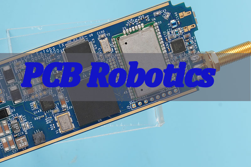
PCB Robotics is the convergence of printed circuit board technology and robotic systems.
It encompasses everything from the PCB design for a line follower robot to the complex, multi-board assemblies inside industrial arms. The PCB in robotics is not just a carrier for components; it is the integral platform that hosts microcontrollers, sensor interfaces, power regulation, and motor drivers, forming the essential backbone for the robot’s “brain” and “nervous system.”
Success in this field hinges on PCBs that are mechanically robust, electrically reliable, and optimized for manufacturability.
How Does PCB in Robotics Enable Precise Control, Sensing, and Motion Execution?
The PCB in robotics acts as the central hub that integrates all subsystems. Its design directly dictates the robot’s capability and performance.
- Data Processing Core: Hosts the main CPU/MPU, running control algorithms and processing data from various sensors in real-time.
- Sensor Fusion Platform: Provides clean, regulated power and precise signal conditioning circuits for a suite of sensors (LiDAR, IMUs, cameras, encoders), ensuring accurate environmental data.
- Power Distribution & Management: Efficiently routes and regulates high-current power to actuators and motors while providing clean, stable low-voltage power to sensitive digital and analog components.
- Motion Control Interface: Contains motor drivers (H-bridges, stepper controllers) and robust connectors that translate control signals into precise physical movement.
- Communication Backbone: Implements various communication protocols (CAN, Ethernet, SPI, I2C) on the board layout to ensure fast, error-free data exchange between all subsystems.
What Are the Core Design Requirements for Reliable Robotics PCB Design?
Robotics PCB design must satisfy a harsher set of requirements than standard consumer electronics. Reliability under stress is paramount.
- Mechanical Robustness: Boards must withstand constant vibration, shock, and potential physical impact. This demands:
- Strategic stiffener placement.
- Reinforced mounting holes (plated or with pads).
- Conformal coating for moisture and dust protection.
- Thermal Management: Motor drivers and processors generate significant heat. Designs must incorporate:
- Thermal relief pads and adequate copper pours for heat spreading.
- Strategic placement of thermal vias under hot components.
- Consideration for metal-core PCBs (IMPCB) for high-power sections.
- Signal Integrity & EMI Control: High-speed digital signals and motor noise must not interfere with sensitive analog sensor lines.
- Careful stack-up planning with dedicated ground planes.
- Proper separation of analog, digital, and power sections.
- Use of filters, ferrite beads, and strategic grounding for motor driver noise mitigation.
- Connector & Interface Reliability: Connectors are common failure points. Designs must specify:
- Locking or high-retention connectors for cables.
- Strain relief features.
- Redundant pins for critical power connections.
How Robotics PCB Assembly Differs From Standard Electronics Manufacturing?
Robotics PCB assembly introduces unique challenges that go beyond populating a standard board. It requires a manufacturer that understands the functional criticality of every joint and component.
- Mixed Technology Focus: Robotics boards often mix large through-hole connectors (for motors), fine-pitch BGAs (for processors), and heavy thermal mass components (like MOSFETs). The assembly process must be optimized for this mix.
- Enhanced Inspection Requirements: Beyond standard AOI, robotics pcbs often require:
- X-ray Inspection: To verify solder joints under large BGAs or hidden terminations.
- In-Circuit Test (ICT) or Flying Probe: For functional validation of complex circuits.
- Stress Testing: Vibration or thermal cycle testing on sample batches.
- Component Qualification: Using extended temperature-range or industrial-grade components is often necessary, requiring stricter supply chain oversight from the assembler.
- Conformal Coating: Applying protective conformal coating is frequently a standard requirement, adding a critical process step to the assembly line.
How PCB Design for Line Follower Robot Improves Stability and Tracking Accuracy?
A line follower robot is a perfect case study in how PCB design directly impacts core performance. An optimized board layout is crucial for stability and accurate tracking.
- Sensor Placement & Symmetry: The IR or optical reflectance sensors must be placed with micron-level precision relative to each other and the board’s centerline. Any asymmetry in the PCB layout creates inherent tracking bias.
- Low-Noise Analog Design: The sensor signals are weak and analog. The PCB design must:
- Provide a clean, regulated analog power supply separate from motor noise.
- Use short, guarded traces from sensors to the analog-to-digital converter (ADC).
- Include proper grounding and filtering to reject electrical noise from the motors.
- Power Delivery for Motors: Sudden motor loads can cause voltage sags that reset the microcontroller. The design must use wide power traces, large power planes, and strategically placed bulk capacitors near the motor drivers.
- Center of Gravity Management: Component placement on the PCB robot itself affects its physical balance. Dense components should be centered and low to prevent tipping during sharp turns.
How to Ensure the Quality for Robot PCB Assembly?
Ensuring quality in robot PCB assembly is a multi-stage, proactive process.
- Design for Excellence (DFX) Review: A collaborative pre-production review between the designer and manufacturer to eliminate manufacturability, testability, and reliability issues before fabrication.
- Incoming Material Inspection: Verifying all components against the bill of materials (BOM) for correctness and checking for moisture sensitivity (MSL) to prevent “popcorning” during reflow.
- Process Control During Assembly: Monitoring key parameters like solder paste deposition, reflow oven temperature profiles, and placement machine accuracy in real-time.
- Comprehensive Post-Assembly Testing: A combination of tests is essential:
- Automated Optical Inspection (AOI): Checks for solder bridges, component misalignment, and presence.
- X-Ray Inspection: Examines hidden solder joints (BGAs, QFNs).
- Functional Testing (FCT): Powers up the board and runs a test program to verify all inputs, outputs, and logic.
Case about PCB in Aero Robotics Projects by BEST Technology
This project entailed the fabrication of a sophisticated 6-layer RF PCB for a mission-critical aero robotics system. The board’s demanding specifications—including hybrid high-frequency materials, complex HDI via structures, and tight impedance control—were designed to ensure superior signal integrity and reliability in a challenging operational environment. The successful execution of this project highlights our capability in advanced robotics pcb assembly and manufacturing.
6-Layer Aero Robotics RF Board Specifications:
| Item | Specification |
|---|---|
| Laminate Combination | Rogers RO4350B + Isola Astra MT77 (Hybrid Lamination) |
| Inner Layer Copper Thickness | 0.5 oz (17.5 µm) |
| Outer Layer Copper Thickness | 0.5 oz (17.5 µm) |
| Trace Width Tolerance | ±1 mil (RF traces) |
| Solder Mask Thickness | ≤ 15 µm (Green solder mask, no legend) |
Why Choose BEST Technology for Mid Volume Robotics PCB Assembly?
BEST Technology is engineered to be the ideal partner for your scale-up phase. We excel at mid volume robotics PCB assembly by removing the traditional barriers between prototyping and mass production.
- Agility Meets Process Rigor: Our production lines are configured for efficient, smaller batches (500-10,000 units) without sacrificing the disciplined processes needed for consistent quality.
- Robotics-Specific Expertise: Our engineers understand the unique demands of motor control, sensor integration, and ruggedized design, providing actionable DFM feedback.
- Integrated Supply Chain Management: We handle the complexity of sourcing and managing the long-tail of specialized components common in robotics BOMs.
- Comprehensive Quality Assurance: From automated inspection to functional testing, we build verification steps into the process to ensure every board meets the reliability demands of a robotic application.
- Transparent Partnership: We provide clear communication, predictable scheduling, and scalable pricing, making us a true extension of your development team.
All in all, PCB Robotics is the foundational engineering discipline that transforms conceptual robotic designs into functional, reliable machines. This guide has detailed the critical considerations in design, assembly, and testing that separate a successful robotic product from a fragile prototype.
Navigating the transition to mid volume robotics PCB assembly requires a partner that understands both the technical complexities and the business need for speed and flexibility. BEST Technology provides this essential partnership, combining agile manufacturing with rigorous quality control to deliver robust, production-ready assemblies that accelerate your path to market. Pls contact us to discuss your project via sales@bestpcbs.com.