What is aluminum PCB etching? Let’s explore its principle, application, etching process, technical parameter, common problems and solutions, differences between copper PCB etching.
Are you troubled with these problems?
- Why does aluminum PCB etching yield stay stuck at 80%?
- How to eliminate copper burrs after etching?
- Is there a permanent fix for thin aluminum warping?
EBest Circuit (Best Technology) can provide service and solution:
- Molecular Reconstruction Etchant: 95%+ yield stability.
- Micro-Etch + Polish Hybrid Process: Ra≤0.8μm surface finish.
- Low-Temp Tension-Control Etching: <0.5% warpage in 0.2mm plates.
Welcome to contact us if you have any inquiry for aluminum PCB etching: sales@bestpcbs.com.
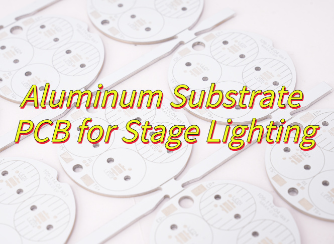
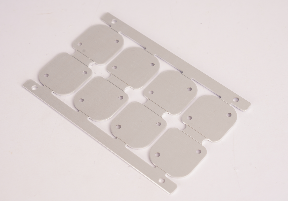
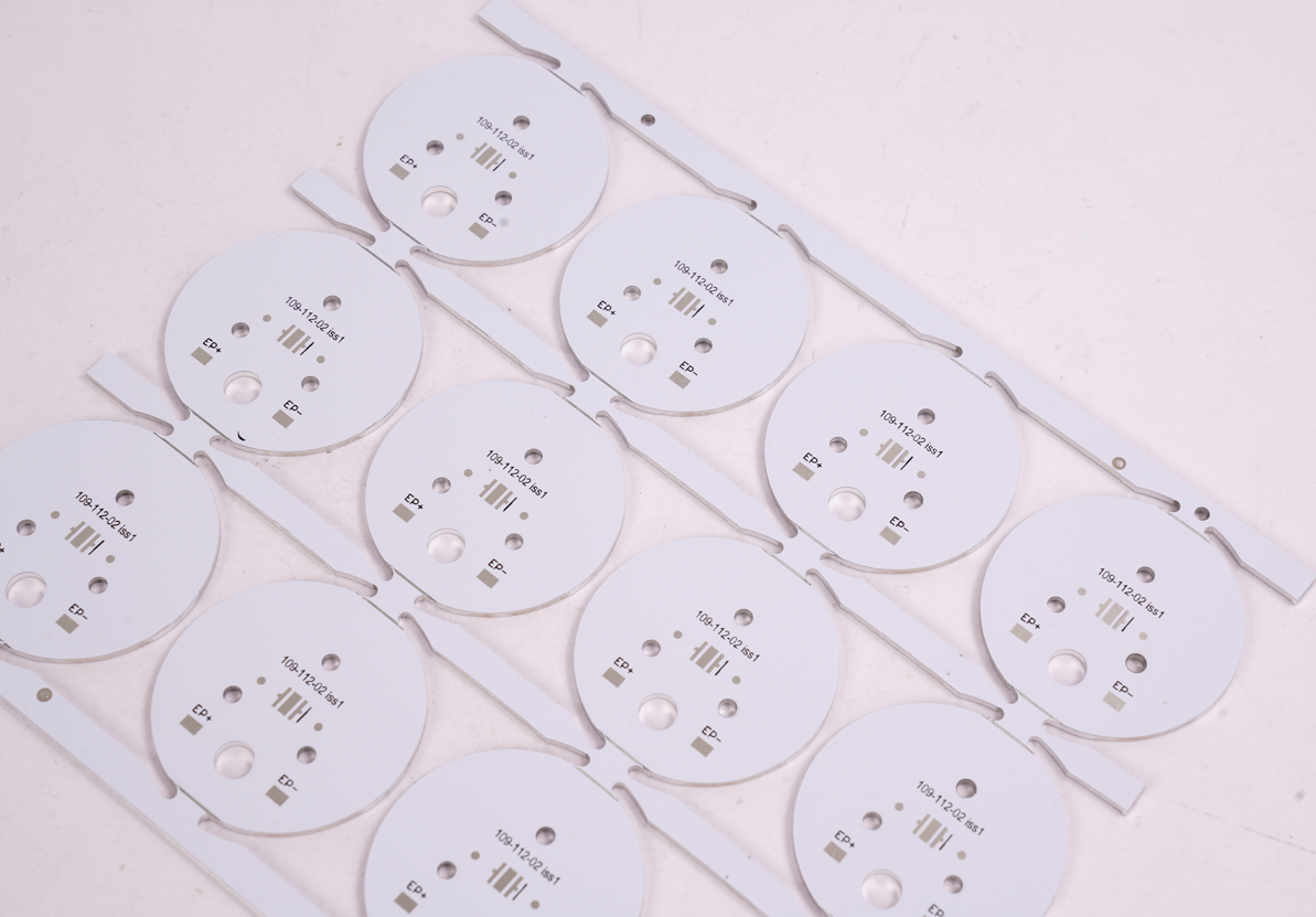
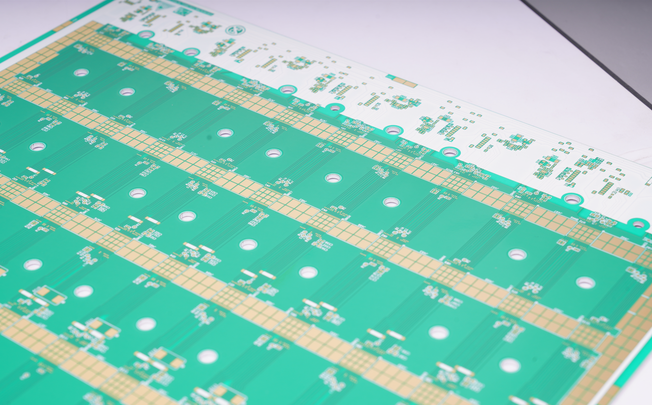
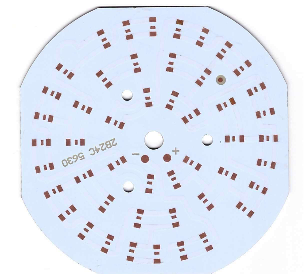
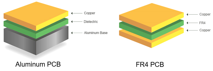
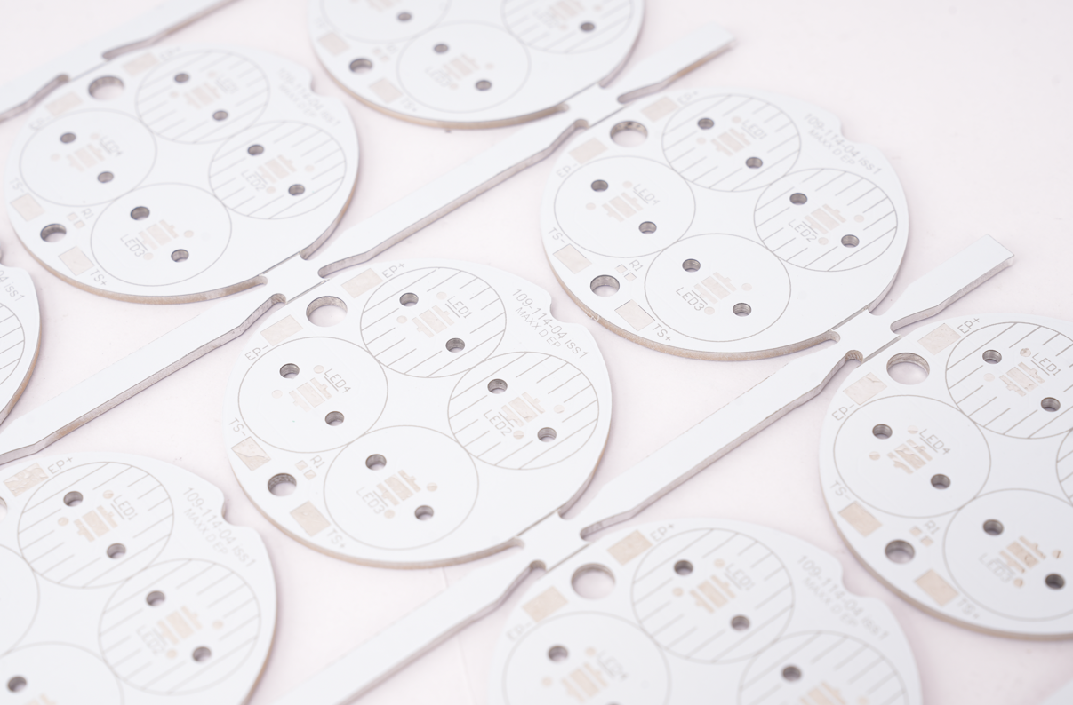
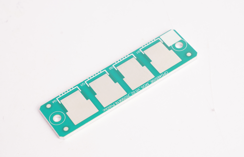
What is Aluminum PCB Etching?
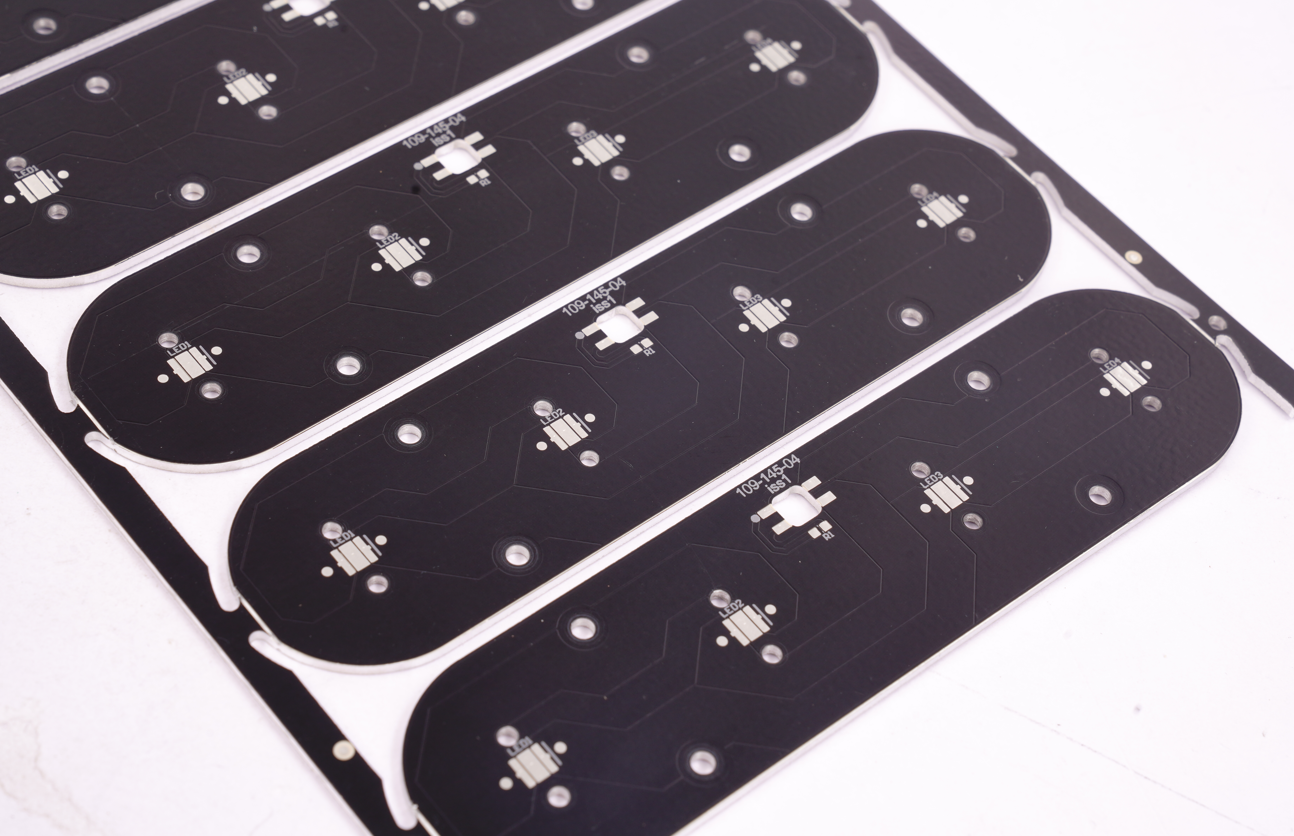
Aluminum PCB etching is a manufacturing process that removes excess copper foil from aluminum based circuit boards using chemical solutions (e.g., acidic copper chloride), forming desired conductive traces while maintaining structural integrity. Unlike traditional FR4 etching, aluminum substrate etching requires strict control of temperature, pressure, and etch rate to minimize side erosion (≤15%) and ensure line width/space accuracy (≥0.2mm), especially for high-power applications like motor control boards.
Principle of Aluminum PCB Etching
Chemical Dissolution Mechanism
- Acidic copper chloride solution selectively attacks exposed copper foil (unmasked areas) while leaving patterned traces intact.
- Aluminum substrate acts as a rigid base, requiring etchant compatibility to prevent substrate corrosion.
Parameter Precision Control
- Temperature: Maintained at 50-60℃ (±2℃ tolerance) to balance reaction speed and side erosion.
- Pressure: 1.5-2.5kg/cm² spray pressure ensures uniform solution contact without over-agitation.
Side Erosion Mitigation
- Etchant flow direction and mask alignment minimize lateral copper dissolution (≤15% side etch rate).
- Critical for 0.2mm+ trace/space accuracy in high-current designs (e.g., motor control PCBs).
Material-Specific Adaptation
- Unlike FR4, aluminum substrates demand slower etch rates (3-5μm/min) to avoid thermal stress-induced warping.
- Post-etch neutralization prevents aluminum-copper galvanic corrosion.
Quality Verification
- Line width/space measured via optical microscopy (±0.02mm tolerance).
- Cross-section analysis confirms trace profile integrity (90° sidewalls).
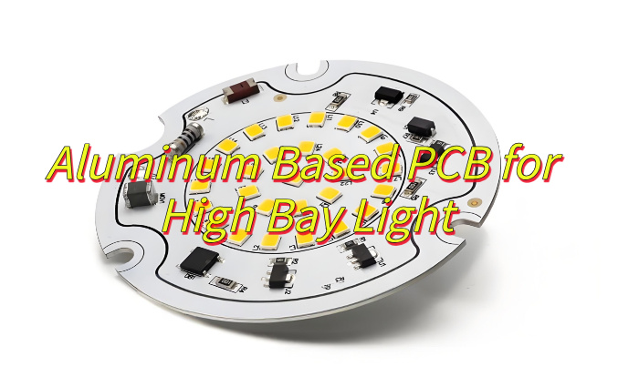
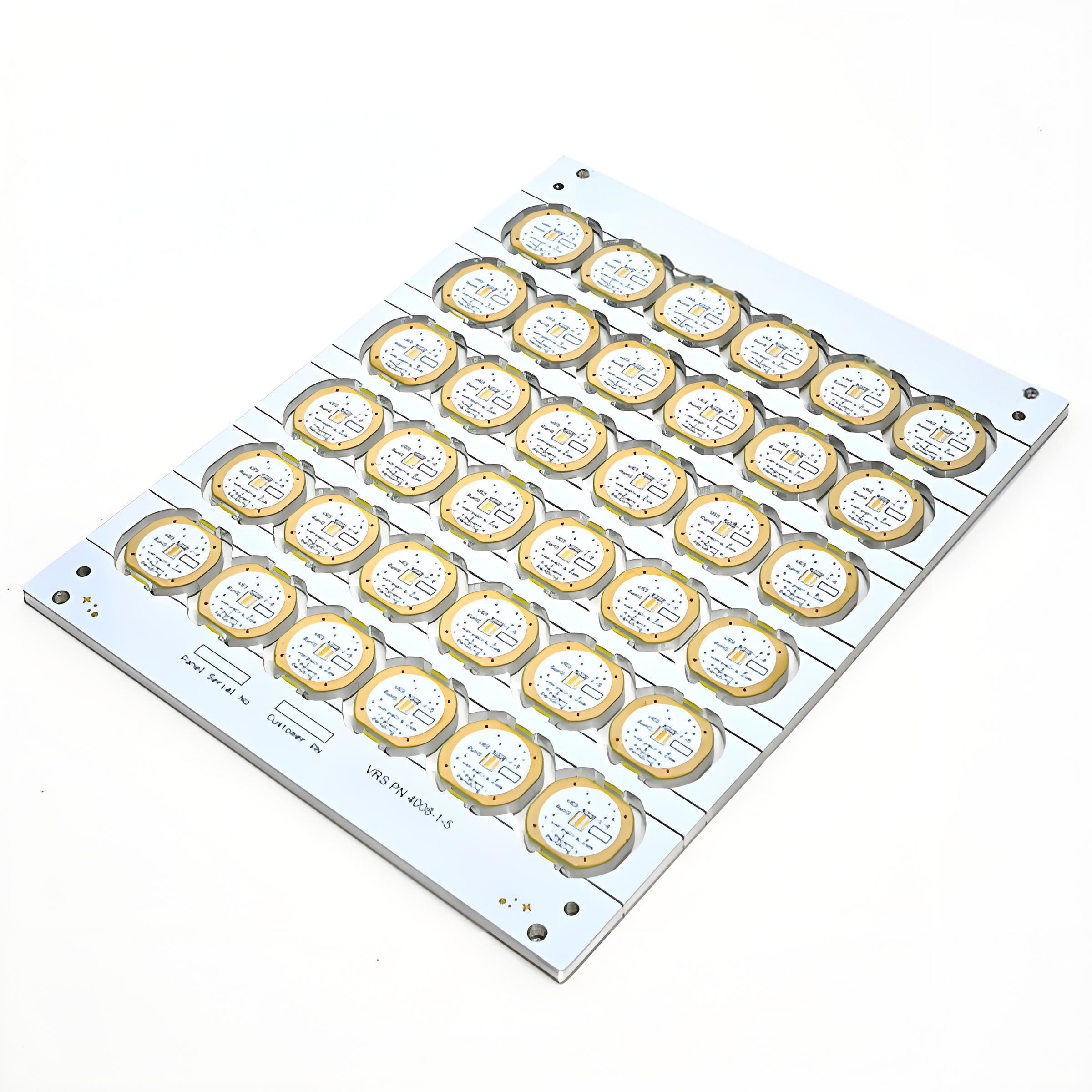
When to Use Aluminum PCB Etching?
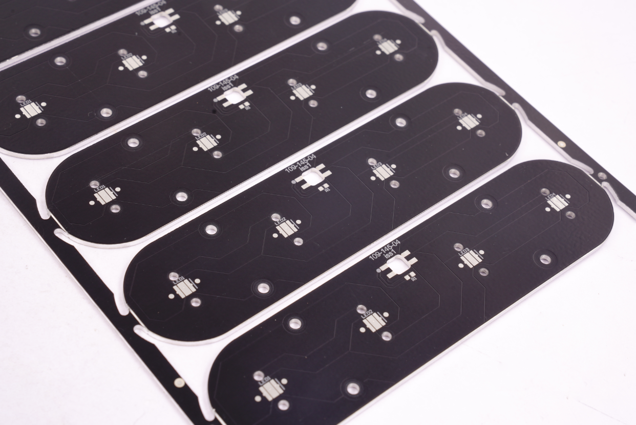
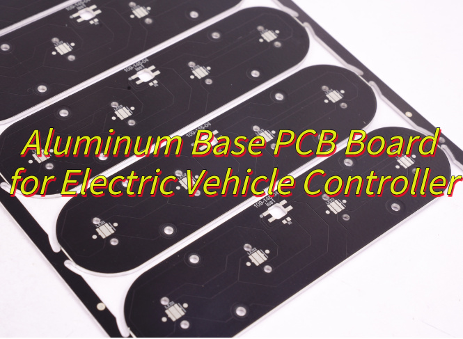
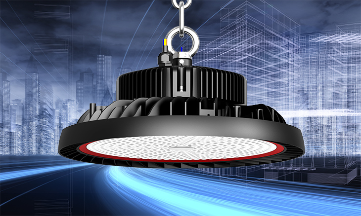
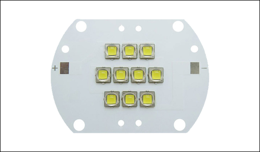
- High-Power Electronics: Motor controllers, inverters, power supplies (>50A current).
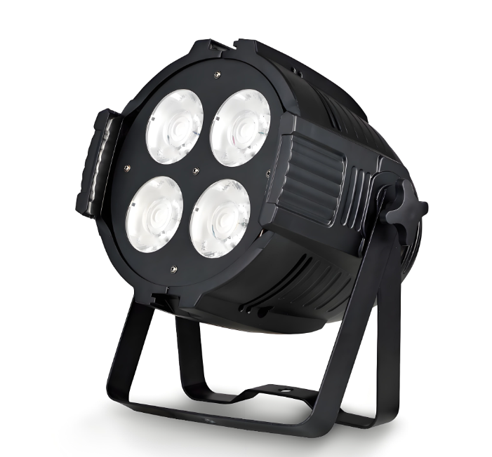
- LED Lighting Systems: High-brightness LED modules, automotive headlights.
- Automotive ECU/Powertrain: Engine control units, battery management systems.
- RF & High-Frequency Applications: 5G base station amplifiers, RF power modules.
- Industrial Control Equipment: PLC modules, servo drive systems.
What is Process of Aluminum PCB Etching?
1. Surface Preparation
- Clean aluminum substrate using alkaline solution to remove oil/oxides.
- Apply micro-etching (e.g., sulfuric acid) to roughen surface for better photoresist adhesion.
2. Photoresist Coating
- Dry-film or liquid photoresist applied via roller coating or spray.
- Thickness controlled at 20-30μm to withstand etching without undercutting.
3. Exposure & Development
- UV exposure through circuit pattern mask (e.g., 365nm wavelength).
- Alkaline developer (e.g., 0.8-1.2% Na2CO3) dissolves unexposed photoresist, revealing copper areas to be etched.
4. Etching Stage
- Acidic copper chloride (CuCl₂ + HCl) solution sprayed at 50-60℃.
- Parameters: 1.5-2.5kg/cm² pressure, 3-5μm/min etch rate.
5. Photoresist Stripping
- Alkaline stripper (e.g., 3-5% NaOH) removes residual photoresist at 40-50℃.
- Ultrasonic cleaning ensures no organic residues remain.
6. Post-Etch Processing
- Acid neutralization (e.g., 5% H₂SO₄) to prevent aluminum-copper galvanic corrosion.
- Dry baking (120-150℃) removes moisture and improves trace adhesion.
7. Quality Inspection
- Optical microscopy checks line width/space (±0.02mm tolerance).
- Cross-section analysis verifies 90° trace sidewalls and zero substrate undercut.
Aluminum PCB Etching Technical Parameter
| Parameter Category | Specification |
| Etching Rate | 1.2-1.8 μm/min (alkaline etching) |
| 0.8-1.5 μm/min (acidic etching) | |
| Temperature Control | 45±2°C (alkaline) |
| 30±2°C (acidic) | |
| Solution Concentration | NaOH: 15-25% (alkaline) CuSO₄: 180-220 g/L (acidic) |
| Spray Pressure | 1.5-2.5 bar (uniform distribution) |
| Conveyor Speed | 1.5-3.0 m/min (adjustable per thickness) |
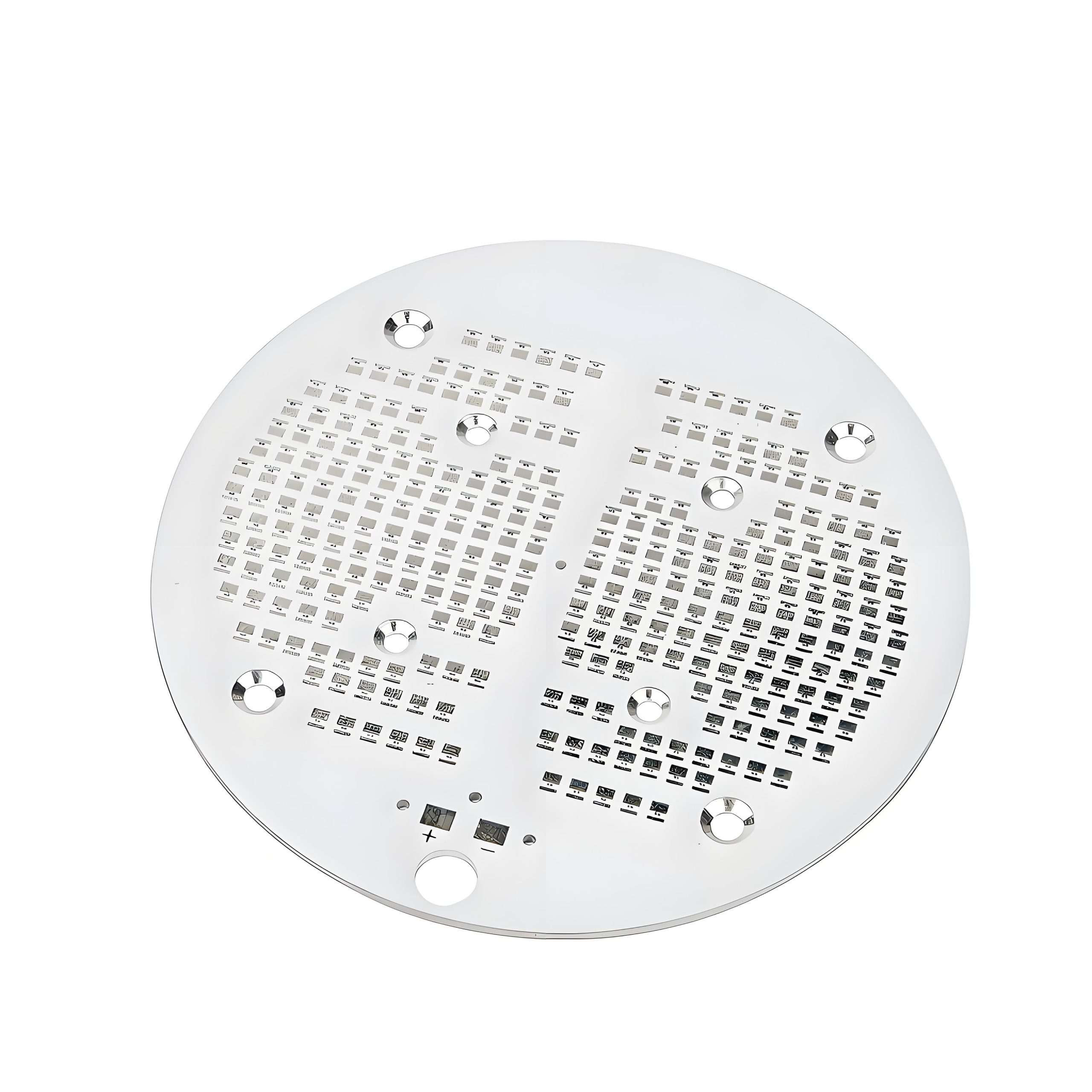
| Copper Thickness Range | 0.5-3.0 oz (17-105 μm) |
| Line Width Tolerance | ±10% (design vs. actual) |
| Waste Treatment | Neutralization (pH 6-8) |
| Heavy metal precipitation (Cu <0.5 ppm post-treatment) | |
| Safety Requirements | Emergency showers |
| Ventilation (≥12 ACH) | PPE: Acid-resistant gloves/goggles |
Common Problems & Solutions in Aluminum PCB Etching Processes
Excessive Side Etching (Jagged Edges/Impedance Instability)
Symptoms: Copper trace sidewalls show burrs, line width deviation >0.03mm.
Solutions:
- Add 5-10% glycerol additive to enhance vertical dissolution.
- Adjust spray pressure to 1.8-2.2kg/cm² (reduce turbulent flow impact)
- Implement pulsating etching: 3-second spray / 0.5-second pause cycles.
Aluminum Surface Corrosion (White Spots/Pitting)
Symptoms: Aluminum substrate shows >0.1mm deep etch pits.
Solutions:
- Maintain real-time pH control at 8.5±0.3
- Use dual-layer liquid photoresist (5μm epoxy base layer)
- Post-etching citric acid neutralization (3% concentration, 45s immersion)
Fine Line Breakage (<0.2mm Trace Fractures)
Symptoms: Micro-trace discontinuities in high-frequency circuits
Solutions:
- Use 18μm ultra-low profile copper foil (RTF copper).
- Optimize pre-bake: 110℃×30min stress relief.
- Slow etching to 2μm/min precision control.
Uneven Etching (Copper Thickness Variation)
Symptoms: >10% copper thickness variation across panel
Solutions:
- Install rotating rack (2-3rpm continuous rotation).
- Optimize nozzle layout with honeycomb matrix (50mm spacing).
- Real-time beta-ray thickness monitoring (3 points per panel).
Residual Copper Slag (Micro-Short Risks)
Symptoms: <50μm copper particles between traces
Solutions:
- Add ultrasonic cleaning (40kHz, 60℃ deionized water).
- High-pressure water jet rinse (8MPa, 45° angle).
- Add 0.5g/L EDTA disodium salt chelating agent.
Differences between Aluminum PCB vs Copper PCB Etching
| Comparison Dimension | Aluminum PCB Etching | Copper PCB Etching |
| Material Properties | Good thermal conductivity but soft; requires corrosion protection. | Excellent conductivity/thermal performance; prone to oxidation. |
| Etchant Composition | Acidic mixed solution (prevents over-etching) | Acidic copper chloride solution. |
| Temperature Control | Low temperature (50-60℃ to prevent deformation) | Medium temperature (50-55℃ for uniformity) |
| Spray Pressure | Low pressure (1.5-2.5kg/cm² to reduce side etching) | Medium pressure (2-3bar for coverage) |
| Side Etch Control | Requires additives + pulsating etching | Adjustable via process parameters |
| Applications | High-power/high-heat scenarios (LED, automotive electronics) | Consumer electronics/communication devices |
Why Choose EBest Circuit (Best Technology) as Aluminum Base PCB Manufacturer?
Reasons why choose us as aluminum base PCB manufacturer:
- 19 Years of Aluminum Substrate R&D Expertise: Specialized in high-power aluminum PCB development since 2006, with over 500 global client projects delivered across industrial lighting, automotive electronics, and communication equipment.
- Dual-Certification Quality System: ISO 9001/IATF 16949 dual certification, compliant with medical (ISO 13485) and automotive standards. 100% AOI inspection ensures zero tolerance for solder bridges, misalignment, or copper residues.
- Industry-Leading Etching Precision: Utilizes pulsating etching process (3-second spray / 0.5-second pause) with 5-10% glycerol additive, achieving ≤15% side etch rate and ±0.02mm line width accuracy, supporting 0.15mm ultra-fine circuit processing.
- Thermal Management Innovation: Proprietary heat dissipation design reduces device operating temperature by 30%, paired with 3W/m·K high-thermal-conductivity aluminum substrates for stable performance in high-temperature environments.
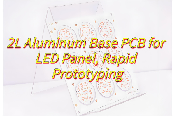
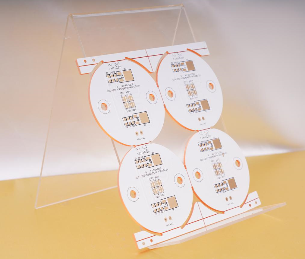
- 24-Hour Rapid Prototyping: Direct import of Altium/PADS design files, coupled with in-house etching lines, enables 24-hour prototype delivery and 48-hour shipment, accelerating time-to-market.
- Free DFM Design Optimization: Engineering team pre-reviews thermal via layouts and trace spacing, proactively mitigating etching defects and reducing rework costs by over 40%, especially for complex multilayer designs.
- Eco-Friendly & Cost-Effective Solutions: Lead-free etching processes and 25% recycled aluminum content meet RoHS/REACH standards while offering budget-friendly options for mass production, balancing performance and affordability.
Welcome to contact us if you have any inquiry for aluminum base PCB: sales@bestpcbs.com.