

SMB PCB is the backbone of modern RF and microwave systems, providing a reliable coaxial interface for signals up to 4 GHz. This article delves into the engineering decisions behind using SMB connectors on printed circuit boards, from footprint design to selecting the right manufacturing partner. We will explore the key aspects of SMB PCB design, the various connector types available, and the critical fabrication controls required for high-frequency success. Are you struggling with signal integrity or connector reliability in your RF designs? You are not alone. Many engineers face significant hurdles when integrating coaxial interfaces like the SMB connector PCB mount into their projects.
What are the typical pain points engineers encounter when working with SMB PCBs?
- Poor Impedance Matching: Inaccurate SMB PCB footprint designs or inconsistent PCB material properties lead to impedance mismatches, causing signal reflections and degrading performance.
- Mechanical Failure: Weak solder joints or an insecure SMB PCB mount can cause connectors to detach from the board under vibration, mating cycles, or routine handling.
- Inconsistent RF Performance: Variations in manufacturing, such as poor plating or tolerance drift, result in unpredictable insertion loss and VSWR, making design validation difficult.
- Supply Chain Complexity: Sourcing reliable components, especially specific variants like the SMB-LR PCB or dealing with long lead times from various China PCB type SMB connector suppliers, can delay projects.
- Assembly and Rework Difficulties: Misalignment during SMT assembly or damaging the PCB during rework of a SMB female PCB connector leads to scrap and increased costs.
At BEST Technology, we address these challenges with a focus on precision and quality. Our solutions are designed to ensure your SMB PCB performs reliably from prototype to mass production.
- Controlled Impedance Fabrication: We utilize high-frequency laminates and rigorous modeling to ensure your SMB PCB footprint translates into a consistent 50Ω transmission line, minimizing signal reflections.
- Robust Mechanical Design Support: Our DFM analysis includes checks for solder pad geometry, plating barrel strength, and reinforcement for SMB PCB mount connectors to prevent mechanical failure.
- High-Frequency Process Control: Tight tolerances on dielectric thickness, copper etching, and surface plating guarantee the stable RF performance of every SMB PCB connector on your board.
- Verified Supply Chain: We have partnerships with reputable PCB type SMB connector manufacturers, ensuring access to genuine components like the SMB-4R-PCB and stable pricing, streamlining your procurement.
- Expert PCBA Process: Our assembly lines are optimized for coaxial connectors, using specialized profiles and inspection techniques to perfectly place your SMB jack PCB connectors without damage.
BEST Technology is a specialized PCB and assembly manufacturer with extensive expertise in high-frequency applications. With factories in China and Vietnam, we offer one-stop services from SMB PCB fabrication to full box-build assembly, supported by certifications like IATF 16949, ISO 13485 and AS9100D. Pls feel free to contact us at sales@bestpcbs.com to discuss your project specifics.
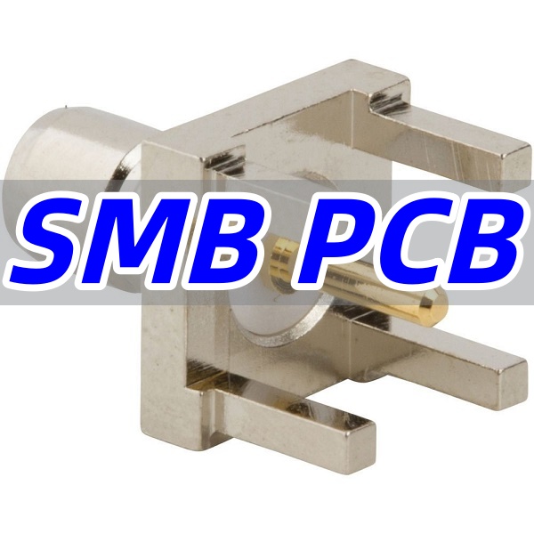
What Is an SMB PCB?
An SMB PCB is a printed circuit board designed to incorporate SubMiniature version B (SMB) coaxial connectors. These connectors provide a snap-on, quick-connect/disconnect interface for RF signals, typically used in applications where space is limited, and frequencies do not exceed 4 GHz.
- Core Function: The primary role of the SMB connector on the PCB is to transition the RF signal from a coaxial cable to a controlled impedance trace on the board with minimal loss and reflection.
- Common Applications: You will find SMB PCB interfaces in telecommunications equipment, automotive sensors, medical devices, and test and measurement instrumentation.
In summary, an SMB PCB is a critical enabling technology for compact RF systems, balancing performance, size, and cost-effectiveness.
How Do SMB PCB Connectors Support RF Signals?
SMB PCB connectors support RF signals by creating a stable, shielded coaxial transmission line that transitions the signal from a cable to a controlled impedance trace on the printed circuit board with minimal loss and reflection. This is achieved through their precise internal and external design, which maintains signal integrity up to 4 GHz.
- Coaxial Structure Miniaturization: The core of an SMB connector’s functionality is its coaxial design, miniaturized for PCB use. It features a central conductor (pin) surrounded by a dielectric insulator, all enclosed within an outer metal shell. This structure confines the electromagnetic field, preventing radiation loss and protecting the signal from external interference.
- Controlled Impedance Interface: High-quality SMB PCB connectors are engineered to present a consistent 50-ohm impedance. The dimensions of the center pin, the dielectric constant of the insulator, and the diameter of the outer shell are precisely controlled. This ensures a smooth impedance match when connected to a standard 50-ohm coaxial cable and a properly designed 50-ohm microstrip line on the PCB, minimizing signal reflections at the connection points.
- Low-Loss Dielectric Materials: The insulator inside the connector is typically made from Polytetrafluoroethylene (PTFE), a material known for its stable dielectric constant and low loss tangent at high frequencies. This minimizes signal attenuation (insertion loss) as the RF signal passes through the connector.
- Robust Shielding: The outer metal shell of the SMB PCB connector provides essential electromagnetic interference (EMI) and radio-frequency interference (RFI) shielding. When this shell is soldered to a continuous ground plane on the PCB, it creates a Faraday cage effect, ensuring the signal remains clean and isolated from noise, and vice versa.
In essence, SMB PCB connectors act as precision-engineered gateways. They support RF signals by preserving the controlled environment of a coaxial cable right up to the point of connection with the PCB, ensuring the signal’s integrity is maintained throughout the entire pathway.
Why Engineers Choose an SMB Connector PCB Mount for Compact RF Boards?
Engineers consistently select the SMB connector PCB mount for space-constrained RF designs due to its optimal blend of size, performance, and reliability. This section explains the key reasons behind this choice.
- Space Efficiency: SMB connectors are significantly smaller than their SMA counterparts, allowing for higher connector density on a PCB. This is crucial for modern, miniaturized electronics.
- Snap-Lock Mechanism: The snap-on coupling mechanism is faster to engage and disengage than a threaded interface (like SMA), simplifying assembly and testing, though it offers slightly less mechanical robustness.
- Good RF Performance: For frequencies up to 4 GHz, SMB connectors provide excellent electrical characteristics, including low VSWR and insertion loss, making them suitable for many commercial and industrial applications.
- Cost-Effectiveness: SMB connectors are generally more economical than higher-frequency alternatives, providing a solid price-to-performance ratio for high-volume production.
The decision to use an SMB connector PCB mount is driven by the need for a compact, cost-effective, and reliable RF interconnection solution that meets the electrical requirements of a vast range of applications.
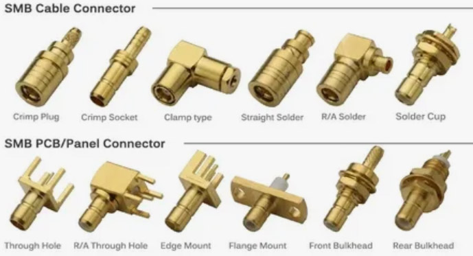
Differences Among SMB Female PCB, SMB Male PCB Connector, and SMB Jack PCB Designs
Understanding the gender and configuration of SMB connectors is essential for correct mating and optimal PCB layout. The terms SMB female PCB, SMB male PCB connector, and SMB jack PCB refer to specific connector configurations.
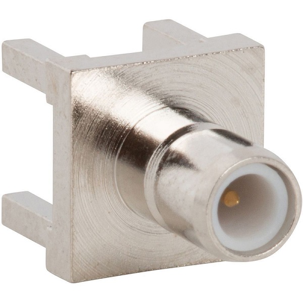
- SMB Female PCB Connector: This connector has the center receptacle (socket) and is typically the panel-mounted or cable-end component. However, when referenced as a “female PCB” part, it usually means a connector that mounts on the board and has an outer shell that accepts the male jack’s snap-ring.
- SMB Male PCB Connector: This connector has the center pin and is the SMB Jack, which mates with an SMB Plug containing a female basket. A SMB male PCB connector is designed to be mounted directly onto the circuit board.
- SMB Jack PCB: This term is often used interchangeably with a PCB-mounted male connector. It is the male connector that inserts into an SMB Plug containing the female basket. A SMB jack PCB connector thru hole version offers superior mechanical strength compared to surface-mount types.
In practice, the key is to ensure your bill of materials (BOM) and layout specify the correct gender (plug or jack) and mounting style (vertical, right-angle, thru-hole, SMT) to ensure proper mating with the corresponding cable or panel connector.
| Name | SMB connector genders |
| SMB Plug | Female basket |
| SMB Jack | Male center pin |
How to Create a Stable SMB PCB Footprint for High-Frequency Layouts?
Creating a stable SMB PCB footprint is paramount for maintaining signal integrity at high frequencies. An improper footprint can lead to impedance discontinuities and poor performance.
- Follow Manufacturer Specs Precisely: The starting point is always the connector manufacturer’s recommended land pattern and drill chart. Do not deviate from these dimensions.
- Ensure a Solid Ground Connection: A low-inductance path to ground is critical. The footprint must include an ample ground plane around and beneath the connector’s outer shield pins. Use multiple vias near the ground pads to connect directly to the ground plane.
- Manage the Impedance Transition: The footprint should be designed to minimize the discontinuity between the connector’s internal impedance and the PCB’s 50-ohm microstrip or stripline. This often involves tuning the size and shape of the pad leading to the signal trace.
- Consider Pad Size for Mechanical Strength: Especially for thru-hole connectors, the plating (PTH) barrel must be robust. For SMT versions, the solder pads must be large enough to create a strong fillet that can withstand mating forces.
A stable SMB PCB footprint is not just a geometric pattern; it is an integral part of the RF circuit. Careful attention to grounding, pad design, and adherence to specifications will ensure a reliable interface.
When to Use an SMB Right Angle PCB Connector vs. Vertical SMB PCB Mount Connector?
The choice between an SMB connector right angle PCB and a vertical SMB PCB mount connector is primarily dictated by the physical constraints and cable routing requirements of the assembly.
- Use a Right-Angle Connector When:
- The coaxial cable needs to be routed parallel to the plane of the PCB to save vertical space. This is common in slim, stacked assemblies.
- You want to reduce the mechanical leverage on the solder joints, as the mating force is directed along the board’s surface rather than perpendicular to it.
- Use a Vertical (Straight) Connector When:
- The cable needs to be routed away from the board, which is typical for external ports or connections to other stacked boards.
- Panel mounting is involved, and the connector must pass through a hole in the enclosure.
Selecting the correct orientation—SMB connector right angle PCB or vertical mount—is a mechanical decision that impacts the overall form factor, cable management, and long-term reliability of the product.
What to Know About China PCB Type SMB Connector Suppliers for RF Coaxial Builds?
Sourcing from China PCB type SMB connector suppliers can be highly cost-effective, but it requires diligence to ensure quality and reliability for your RF coaxial builds.
- Quality Spectrum: The market ranges from suppliers producing connectors for consumer electronics to those specializing in high-reliability industrial and automotive grades. It is critical to verify the supplier’s target market and quality controls.
- Plating and Materials: Inquire about the plating material and thickness. Gold plating over nickel is standard for good corrosion resistance and stable contact resistance. The dielectric material inside the connector should be PTFE for stable performance.
- Manufacturing Partnership: Look for a supplier that acts as a partner. The best China PCB type SMB connector factory will provide detailed specifications, samples for testing, and be transparent about their manufacturing process.
- Leverage Your PCBA Partner: A skilled PCBA manufacturer like BEST Technology has existing relationships with vetted component suppliers. We can manage the sourcing of a China PCB type SMB RF connector, ensuring component authenticity and performance, simplifying your supply chain.
Working with reputable China PCB type SMB connector suppliers can yield great value, but the process demands technical vetting and, ideally, the support of an experienced manufacturing partner.
How SMB-LR PCB, SMB-4R-PCB, and SMB-R-PCB-SMT Variants Fit Different RF Applications?
Specific SMB product variants like SMB-LR PCB, SMB-4R-PCB, and SMB-R-PCB-SMT are engineered to meet distinct mechanical and assembly requirements.
- SMB-LR PCB (Long Reach): This variant features a longer solderable surface, providing enhanced mechanical stability after mounting. It is ideal for applications subject to high vibration or where the connector may undergo significant mating force.
- SMB-4R-PCB (4 Ridge): The “4R” typically refers to a connector with four external ridges or contacts for the outer shield. This design offers a superior, low-inductance ground connection to the PCB, which is beneficial for higher-frequency performance within the SMB range.
- SMB-R-PCB-SMT (Surface Mount Technology): This is a surface-mount version, often with a right-angle configuration. The SMB-R-PCB-SMT is designed for high-speed automated assembly, saving time and cost compared to thru-hole mounting, which requires a separate soldering process.
Understanding these variants allows engineers to select the optimal SMB PCB connector for their specific application, whether the priority is mechanical ruggedness, RF performance, or assembly efficiency.
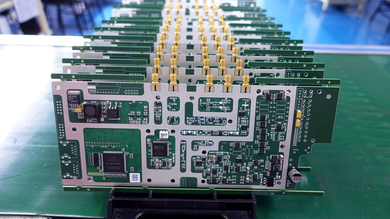
Why RF Teams Choose BEST Technology for SMB PCB Fabrication and PCBA Assembly?
RF design teams partner with BEST Technology because we provide a seamless, high-quality manufacturing pathway for complex SMB PCB projects. Our capabilities are tailored to the demands of high-frequency electronics.
- PCB Fabrication Strengths: We use high-frequency materials like Rogers, Taconic, and Isola, and maintain tight impedance control (typically ±10%) with controlled-depth drilling for back-drilled vias. Our processes ensure precision for even the most demanding SMB PCB footprint.
- Comprehensive PCBA Capabilities: We offer both SMT and thru-hole assembly, supported by rigorous inspection (AOI, X-Ray) and testing (ICT, Functional Test). We expertly handle the reflow profile requirements for SMB PCB mount connector to prevent damage.
- Stringent Quality Systems: Our IATF 16949 (automotive), AS9100D (aerospace), and ISO 13485 (medical) certifications provide confidence for mission-critical applications.
- Tailored Services: We offer free DFM/DFA reviews, RF stack-up consulting, quick-turn prototypes, and full box-build assembly with coaxial cable integration.
SMB PCBs are a critical link in the RF signal chain, demanding precision from design through assembly. This guide has covered the essential aspects of selecting, designing, and manufacturing PCBs with SMB connectors to achieve robust RF performance. By choosing a partner like BEST Technology, you gain access to specialized manufacturing expertise, rigorous quality controls, and a seamless one-stop service that ensures your SMB PCB designs perform as intended. Our global manufacturing footprint and commitment to engineering support make us the ideal choice for your next project.
Ready to get a quote for your professional SMB RF PCB? Pls send your Gerber files, BOM, and connector specifications to sales@bestpcbs.com for a fast and comprehensive review.