

SMA connector PCB refers to a specialized radio frequency (RF) connector designed for mounting on printed circuit boards to facilitate secure coaxial cable connections in high-frequency applications, such as telecommunications and wireless devices. This comprehensive guide will explore everything from SMA connector types and mounting methods to design considerations, helping you make informed decisions for your connector SMA PCB projects.
Are you facing challenges in integrating SMA connectors into your PCB designs without compromising performance?
- Difficulty selecting the right SMA connector type (e.g., surface mount vs. edge mount) for specific frequency needs.
- Poor PCB layout and footprint design causing impedance mismatches and signal loss.
- Soldering errors during assembly, resulting in weak connections or damage to the connector.
- Inadequate mechanical stability, especially in high-vibration environments.
- Limited availability of cost-effective, high-quality SMA connectors that meet industry standards.
To overcome these hurdles, here are five solutions from a professional PCB manufacturer’s standpoint:
- Providing a diverse portfolio of SMA connector types, including surface mount SMA connectors and edge mount options, tailored to various applications.
- Offering expert guidance on SMA connector PCB footprint and layout optimization to minimize signal interference.
- Implementing robust soldering protocols and support for precise PCB mount SMA connector techniques.
- Ensuring connectors with reinforced designs for durability, such as right-angle PCB mount variants.
- Supplying reliable, affordable SMA PCB connectors with quick turnaround times.
BEST Technology is a trusted expert in PCB and PCBA manufacturing, with a focus on RF components like SMA connector PCBs. We combine advanced engineering with quality assurance to deliver SMA connector PCB solutions that enhance signal integrity and reliability. For inquiries, reach us at sales@bestpcbs.com.
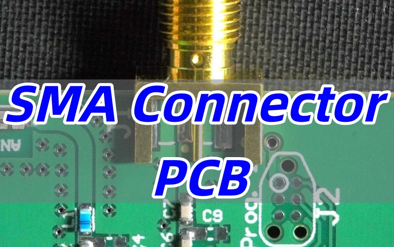
What is SMA Connector PCB?
An SMA connector PCB is a coaxial RF connector soldered or mounted directly onto a circuit board to enable high-frequency signal transmission, typically up to 18 GHz.
It consists of a center conductor and outer shield, ensuring minimal loss in applications like GPS, Wi-Fi, and test equipment.
In summary, this component is vital for maintaining signal quality in compact electronic designs.
What are the Types of SMA Connector PCB Available for Different Applications?
SMA connector PCB solutions come in various forms to match different mounting requirements, space constraints, and RF performance goals. Choosing the correct type is critical to achieving stable impedance, minimal signal reflection, and long-term reliability in RF, communication, or IoT applications.
Below are the main types of SMA connector PCBs, classified by their installation method, orientation, gender, and functionality.
Ⅰ. Classification by Mounting Style
Surface Mount SMA Connector PCB (SMT Type)
- A surface mount SMA connector PCB attaches directly to the board pads using solder reflow during SMT assembly. This surface mount SMA connector is ideal for compact boards that demand high-density layouts, such as small RF modules or wireless transceivers.
- Its low profile and consistent impedance make it popular in SMA connector PCB design where stability and automation efficiency are priorities.
- Common variations include SMA PCB mount connector and SMA connector PCB footprint designed for automated placement systems.
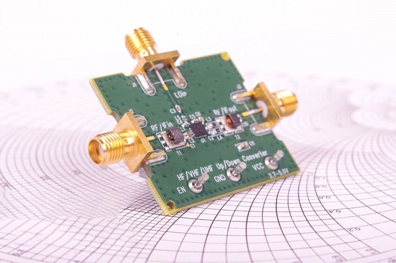
Edge Mount SMA Connector PCB
- The edge mount SMA connector PCB is positioned at the edge of the board, allowing direct connection between the SMA to PCB interface and external coaxial cables. This SMA PCB edge mount connector minimizes trace length and signal loss, especially in high-frequency designs.
- Typical models include male edge mount SMA connector PCB and female edge mount SMA connector PCB, widely used in communication systems and RF evaluation boards.
- Designers often reference the SMA edge connector footprint when laying out PCB edges for precise soldering alignment.
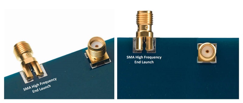
End-Launch SMA Connector PCB
- Used primarily for testing or high-frequency transmission, the SMA end-launch PCB connector extends from the board’s edge in line with the microstrip or coplanar waveguide. It provides excellent impedance matching and low insertion loss, making it the top choice for lab instruments, RF analyzers, and 5G modules.
Ⅱ. Classification by Connector Orientation
Straight SMA Connector PCB
- A SMA connector straight PCB mounts vertically, enabling direct top-entry cable connections. This design suits devices with ample vertical clearance and applications requiring a SMA connector PCB 50 right impedance path.
- This style supports both SMA male connector PCB and SMA female PCB connector configurations.
Right-Angle SMA Connector PCB
- The right-angle SMA connector PCB bends the interface 90 degrees relative to the board surface, optimizing space usage. It is frequently used in compact enclosures or products with limited height, such as IoT sensors.
- Variants like SMA connector right angle PCB mount, SMA connector PCB angle, and SMA female angle PCB mount RF connector are available to match different design layouts.
Ⅲ. Classification by Gender Type
Male SMA Connector PCB
- The SMA male connector edge PCB has a center pin and threaded outer body, used for connecting to female SMA cables or adapters.
- Whether in SMA to PCB connector or SMA connector on PCB configurations, it offers firm mechanical retention and consistent RF contact.
- This type can be found in both straight and angled orientations and is common in radio, antenna, and GPS modules.
Female SMA Connector PCB
- The female SMA connector PCB serves as a jack with an inner sleeve to receive male pins. Standard variants include SMA connector PCB 13mm, SMA connector 16mm PCB, and PCB female SMA connector.
- It’s a frequent choice in communication baseboards, LTE routers, and SMA connector for PCB antenna interfaces due to its secure coupling and reliable signal integrity.
Reverse-Polarity SMA Connector PCB (RP-SMA)
- A reverse-polarity SMA connector PCB (RP-SMA) modifies the pin arrangement—using a male housing with a female pin or vice versa—to prevent accidental connection to standard SMA types.
- This variation is often used in Wi-Fi modules and Bluetooth devices to meet regulatory compliance for antenna connections.
- Both RP-SMA PCB mount connector and RP-SMA PCB adapter configurations are common in secure RF systems.
Ⅳ. Classification by Functional Design
SMA PCB Adapters
- SMA connector PCB adapters help bridge different mounting orientations or gender types. They simplify the process when redesigning a layout or integrating preassembled SMA cables into new RF boards.
- Typical options include SMA to PCB adapter, SMA PCB connector to PCB, and SMA PCB mount connector for flexible integration. These are critical for prototyping or upgrading existing SMA systems.
When designing a SMA PCB connector, engineers should account for:
- SMA connector PCB footprint and pad layout accuracy to maintain 50-ohm impedance.
- The SMA connector PCB size and placement to avoid mechanical interference.
- Proper soldering methods—knowing how to solder SMA connector to PCB is essential to avoid cold joints or impedance mismatches.
- Use of precision alignment tools for PCB edge mount SMA connector installation to ensure solid RF contact and mechanical support.
To conclude, selecting the right SMA connector PCB mount depends on multiple factors—mounting method, orientation, gender, and signal requirements. Each type serves a specific role, from compact surface mount SMA connector layouts to precision end-launch SMA PCB edge connectors used in high-frequency applications.
At EBest Circuit (Best Technology), we specialize in advanced SMA connector PCB design and circuit board manufacturing for RF modules, antenna boards, and high-speed communication systems.
Our PCBs are produced under ISO9001, ISO13485 (Medical), IATF16949 (Automotive), and AS9100D (Aerospace) certifications, backed by a full MES traceability system and rigorous impedance control.
Whether you require custom SMA connector PCB layout, SMA connector PCB mount, or complete SMA PCB assembly, EBest Circuit (Best Technology) offers the precision engineering and professional support you need to achieve reliable RF performance.
How Many Ways of SMA Connector PCB Mount can be Used in Your Design?
Mounting methods for SMA connectors influence stability and signal integrity. The primary approaches are:
- Surface mounting: The connector is soldered onto PCB pads, suitable for automated assembly and high-volume production.
- Through-hole mounting: Pins insert into drilled holes, offering strong mechanical bonds for rugged environments.
- Edge mounting: The connector attaches to the board’s periphery, ideal for applications requiring external access.
- Hybrid mounting: Combines surface and through-hole elements for enhanced reliability.
These methods cater to different design priorities, such as ease of soldering or resistance to stress. By evaluating your project’s demands, you can choose the best mount to prevent issues like dislodgement.
What are the Functions of SMA Connector on PCB in Modern Electronics?
SMA connectors on PCBs serve critical roles in modern electronics:
- Signal transmission: They enable low-loss RF signal transfer between boards and cables, crucial for 5G and IoT devices.
- Interfacing: Facilitate connections with antennas, amplifiers, and test equipment, as seen in SMA connector PCB adapters.
- Impedance matching: Maintain 50-ohm impedance to reduce reflections, ensuring data accuracy.
- Modularity: Allow for interchangeable components, simplifying upgrades and repairs.
In short, these functions support high-frequency performance and flexibility, making SMA connectors indispensable in advanced systems.
How to Select SMA Connector on PCB for Your Projects?
Choosing the right SMA connector involves several factors:
- Frequency range: Opt for connectors rated for your operating frequency, e.g., up to 18 GHz for most RF apps.
- Mounting style: Select based on board space—for instance, a right-angle SMA connector PCB for compact designs.
- Gender and interface: Decide between male and female connectors, considering mating compatibility.
- Environmental factors: Choose materials like brass or stainless steel for durability in harsh conditions.
- Cost and availability: Balance quality with budget, sourcing from reliable suppliers like BEST Technology.
By prioritizing these aspects, you can avoid common pitfalls and enhance project success.
What are Considerations for SMA Connector PCB Footprint and Layout?
Proper footprint and layout are essential for SMA connector performance:
- Footprint accuracy: Ensure the SMA connector footprint matches datasheet specs to avoid misalignment.
- Trace design: Use controlled impedance traces (e.g., 50 ohms) and minimize length to cut losses.
- Grounding: Implement a solid ground plane around the connector to shield against noise.
- Clearance: Maintain adequate spacing from other components to prevent interference.
- Via placement: Add vias near the connector for stable grounding, but avoid signal path disruptions.
Adhering to these guidelines, as part of SMA connector PCB design, minimizes signal degradation and boosts reliability.
How to Solder SMA Connector to PCB?
Soldering an SMA connector requires precision:
- Preparation: Clean the PCB pads and connector leads to remove oxidation.
- Application: Use a fine-tip soldering iron and lead-free solder, applying heat briefly to avoid thermal damage.
- Alignment: Position the connector correctly on the footprint before soldering.
- Technique: For surface mount SMA connectors, apply solder paste and reflow evenly; for through-hole, fill holes completely.
- Inspection: Check for cold joints or shorts with a microscope.
This process, when done carefully, ensures a durable connection without compromising the SMA connector PCB’s electrical properties.
How to Attach SMA Antenna Signal to PCB?
Attaching an SMA antenna signal involves:
- Connector selection: Use an SMA female PCB connector or edge mount type for seamless antenna integration.
- Routing: Direct the RF trace from the connector to the antenna input with minimal bends.
- Matching networks: Add components like capacitors or inductors to match impedance.
- Testing: Verify signal strength with a network analyzer post-assembly.
This approach guarantees efficient signal transfer, critical for wireless devices.
Why Choose EBest Circuit (Best Technology) for SMA Connector PCB and PCBA Projects?
BEST Technology stands out for connector SMA PCB projects due to:
- Expertise: We offer tailored SMA PCB connector to PCB solutions, from SMA PCB connector selection to full PCBA assembly.
- Quality: Our SMA PCB connectors undergo rigorous testing for VSWR and durability. Our PCB & SMT factory are fully compatible with ISO 9001, ISO 13485, IATF 16949, AS9100D, UL, REACH, and RoHS.
- Support: We provide end-to-end guidance on SMA connector PCB design and circuit board manufacturing.
- Speed: Rapid connector SMA PCB prototyping and production reduce time-to-market.
- Small Quantity Support: We specialize in medium quantity to small quantity PCB orders with fast turnaround times. All of our PCB products are without any MOQ requirement, including FR4 PCB, flexible circuits, Rigid-flex circuits, metal core PCB, and ceramic PCB.
In a nutshell, SMA connector PCB is a key component for high-frequency electronic systems, enabling efficient RF connectivity. This article has detailed how to choose the best SMA connector by evaluating types, mounts, and design factors. BEST Technology excels in delivering top-tier SMA connector PCBs with comprehensive PCBA services. For assistance, contact us at sales@bestpcbs.com.