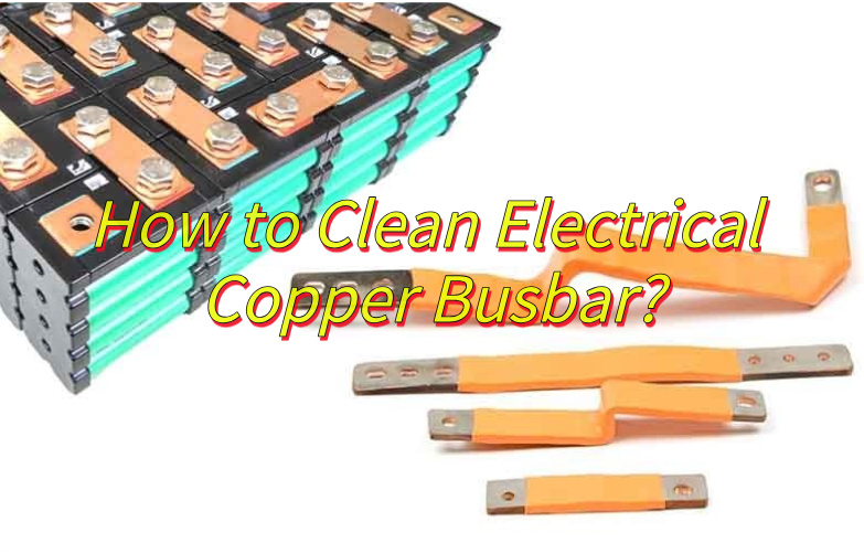
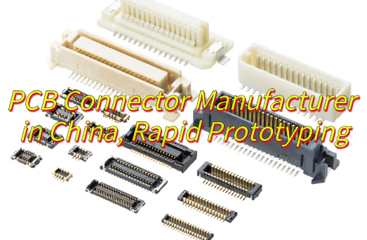
What is a PCB connector? Let’s discover its technical parameter, types and applications, how to choose and how to fix PCB connectors.
Are you troubled with these questions?
- Frequent intermittent failures causing high rework rates?
- Unstable supply chain delaying shipments?
- Bulk connectors wasting PCB space?
EBest Circuit (Best Technology) can provide you service and solutions:
- Universal Compatibility: Full-range 0.5–2.54mm pitch connectors, plug-and-play.
- 10-Year Supply Guarantee: Tier-1 direct sourcing, zero stockouts.
- Space-Saving Design: Low-profile side-mount (≤3mm H), slash BOM cost.
Welcome to contact us if you have any request for PCB connector: sales@bestpcbs.com.
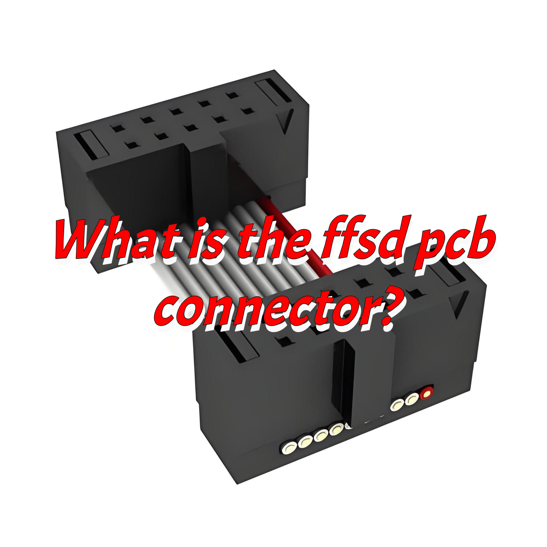
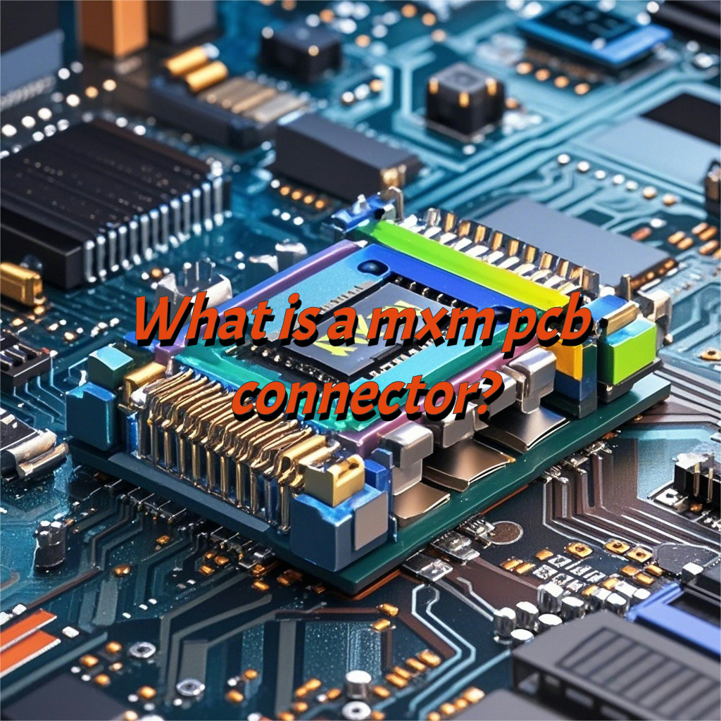
What Is a PCB Connector?
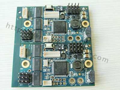
A PCB connector is an electro-mechanical component designed to establish reliable electrical and mechanical connections between a printed circuit board (PCB) and external devices, components, or other PCBs, typically consisting of conductive contacts (e.g., pins, sockets, or pads) housed in insulating materials (e.g., plastic or ceramic) to ensure signal integrity, power distribution, and secure mounting.
PCB Connector Technical Parameter
| Parameter Name | Parameter Description |
| Rated Current | 1A-100A (varies by model) |
| Contact Resistance | ≤50mΩ (contact point) |
| Insulation Resistance | ≥1000MΩ (normal state) |
| Dielectric Withstand Voltage | 500V AC/1min |
| Mating Cycles | ≥5000 cycles (standard type) |
| Pin Pitch | 0.3mm-5.0mm (typical range) |
| Connection Type | SMT/THT |
| Latching Mechanism | Latch/Screw/Push-pull |
| Operating Temperature | -40°C to 125°C (wide-temperature type) |
| Protection Grade | IP67/IP68 (dust/water-resistant) |
| Corrosion Resistance | Salt spray/chemical solvent resistant |
| UV Resistance | UV aging resistant (outdoor type) |
| Material Type | Copper alloy/stainless steel/phosphor bronze |
| Surface Treatment | Gold/tin/nickel plating |
| Certification Standards | UL/CE/RoHS/ISO |
| Dimensional Tolerance | ±0.1mm (precision type) |
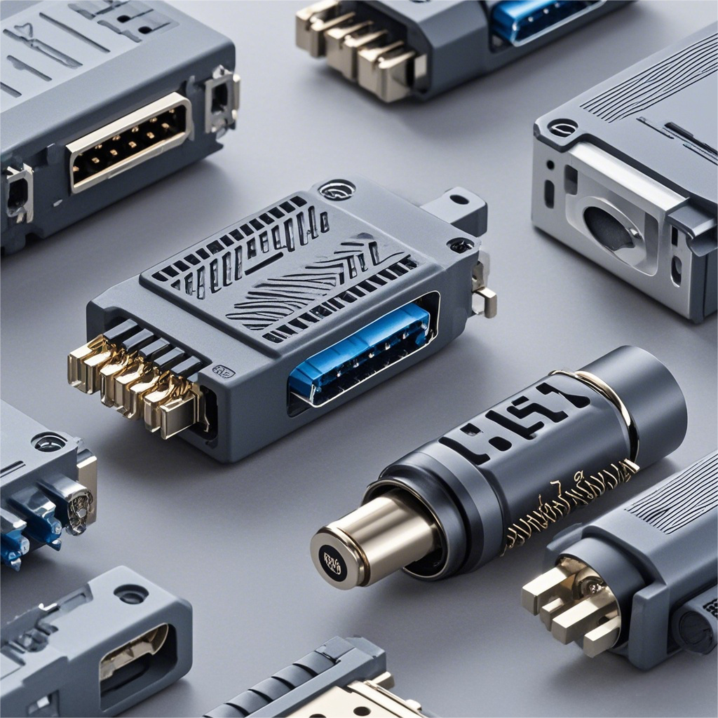
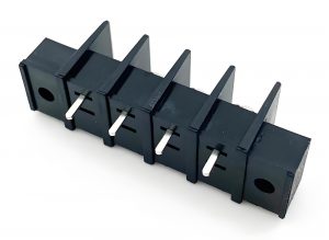
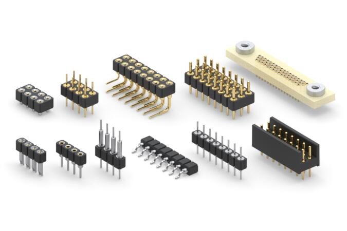
What Are the Three Types of Connectors?
Wire-to-Board Connectors
- Function: Establish reliable electrical connections between external wires/cables and PCBs, suitable for power input, sensor interfaces, and similar applications.
- Features: Plug (wire end) + receptacle (board end) configuration with locking mechanism for secure connection.
- Advantages: Enable quick plugging/unplugging and sustained use in high-vibration environments, meeting dynamic application requirements.
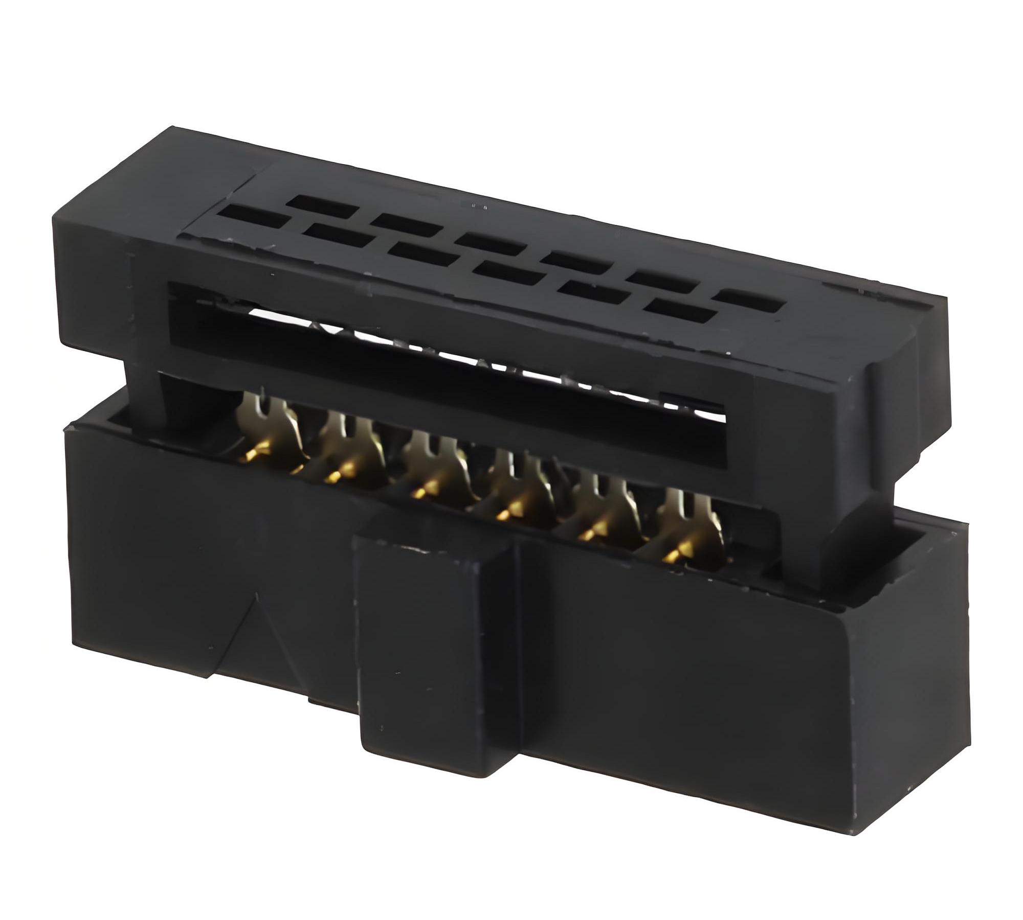
Board-to-Board Connectors
- Function: Enable vertical/horizontal interconnection of multiple stacked PCBs, ideal for compact devices like smartphones and server motherboards.
- Features: Available in through-hole, surface-mount, or spring-loaded styles, supporting high-density signal transmission.
- Advantages: Some models feature ZIF (Zero Insertion Force) for lossless plugging/unplugging, enhancing assembly efficiency and reliability.
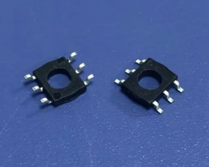
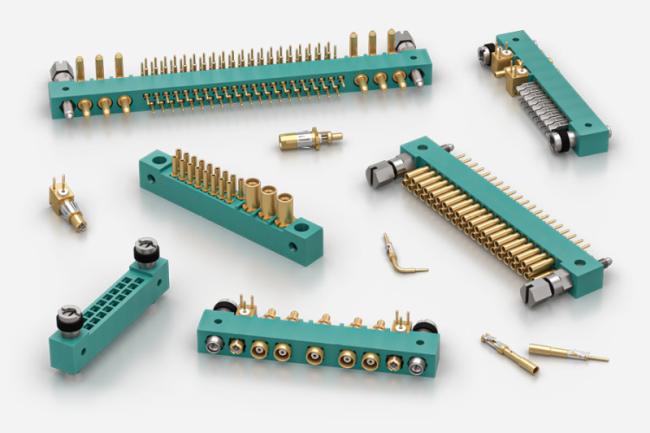
Socket Connectors
- Function: Provide pluggable connections for integrated circuits (e.g., CPUs, FPGAs) or functional modules (e.g., memory modules, SIM cards).
- Features: Gold fingers/spring pin contact design with keying notches to prevent mis-insertion.
- Advantages: High contact reliability and low impedance design, suitable for computers, communication equipment, industrial control, and similar applications.
What Are Applications of PCB Connectors?
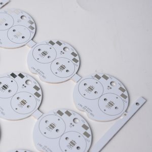
- Consumer Electronics: Mobile phone or tablet charging ports, headphone jacks, and USB-C data ports.
- Industrial Automation: Connections for PLC controllers, sensor networks, and motor drive modules.
- Automotive Electronics: Connections for onboard ECUs, entertainment systems, and battery management modules.
- Communications Infrastructure: Internal inter-board interconnects for base station antennas, routers, and switches.
- Medical Electronics: Interfaces for medical monitors, ultrasound equipment, and implantable devices
- Aerospace equipment: Satellite communication modules, flight control systems, and space probe connections.
- IoT devices: Smart sensors, smart home controllers, and wearable device connections.
How to Choose PCB Connectors?
1. Clarify Application Requirements and Scenarios
- Electrical Parameters: Define rated voltage, current, signal types (digital, analog, high-speed), and transmission rates (e.g., PCIe, CAN bus). Automotive ECU requires high voltage resistance (400V-900V) and EMI immunity, while consumer electronics prioritize low power and miniaturization.
- Mechanical Constraints: Evaluate PCB size, layout space, mounting methods (SMT/through-hole/crimp), and pin pitch (0.4mm-2.54mm). Compact devices (wearables) need ultra-thin or vertical connectors; industrial equipment demands shock resistance.
- Environmental Conditions: Consider temperature range (-40°C to 125°C), humidity, waterproof rating (IP67/IP68), chemical corrosion (oil, salt spray), and vibration/shock levels. Outdoor devices require UV protection; medical devices need biocompatibility.
2. Select Connector Type and Specifications
- Type Matching: Choose based on scenarios—board-to-board (multi-board stacking), wire-to-board (power/sensors), edge connectors (high-speed cards), backplane connectors (servers), or RF connectors (high-frequency signals). 5G devices need low-loss, low-VSWR RF connectors.
- Specification Details: Confirm pin count, terminal finishes (gold/tin plating), contact resistance (≤50mΩ), insulation resistance (≥1GΩ), and mating cycles (50-10,000). High-frequency designs need shielding to reduce crosstalk; high-current applications require low-resistance contacts.
3. Evaluate Performance and Reliability
- Signal Integrity: High-speed signals require impedance matching (50Ω single-ended/100Ω differential) to avoid reflections. Use shielding or ground pins to minimize EMI/ESD interference. Simulation tools (HyperLynx) validate signal behavior.
- Mechanical Durability: Test mating force, locking mechanisms (latches/screws), shock resistance (LV214/USCAR standards), and thermal cycling. Industrial devices pass vibration tests (ISO 16750).
- Environmental Protection: Verify waterproof seals (O-rings/potting), temperature-resistant materials (PBT/PPS), and corrosion-resistant coatings (nickel/gold plating). Automotive connectors pass salt spray tests (ASTM B117).
4. Optimize Cost and Production Compatibility
- Cost Control: Balance performance and cost, premium connectors (TE Connectivity) for high-end scenarios; budget options (local suppliers) for mass production. Consider customization costs (mold fees) and volume benefits.
- Production Compatibility: Select packaging (tape/reel/tray) and mounting methods (reflow/crimp) compatible with automation. SMT connectors support high-speed assembly; crimp connectors avoid soldering heat damage.
- Supply Chain Management: Prioritize local/reliable suppliers for shorter lead times. Validate supplier certifications (ISO 9001) and technical support.
5. Validate and Maintain Long-Term
- Prototype Testing: Verify electrical performance (multimeter/oscilloscope), mechanical stability (mating tests), and environmental suitability (thermal/vibration tests) on prototype boards.
- Long-Term Maintenance: Track supplier material changes via BOM lists to ensure compatibility. Stock spare parts for emergencies. Regularly inspect connectors for aging (oxidation/loosening) and update design standards.
- Industry Compliance: Adhere to standards (IPC/IEC/SAE) and customer requirements (automotive AEC-Q200) to avoid compliance risks.
How to Fix a PCB Connector?
1. Diagnose the Cause of Failure
- Inspect Appearance: Examine the connector for physical damage (bent pins, cracked housing, broken solder joints) or signs of corrosion/oxidation (green rust, white spots).
- Test Contact: Use a multimeter to check continuity between connector pins and PCB pads, identifying opens, shorts, or poor connections.
- Assess Environment: Consider environmental factors like humidity, heat, vibration, or physical impacts that may cause issues (e.g., cold solder joints, loose connectors).
2. Prepare Tools and Materials
- Essential Tools: ESD wrist strap (prevent static damage), tweezers (precision handling), magnifier/microscope (detail inspection), soldering station/iron (temperature-controlled), desoldering braid/pump (clean solder).
- Consumables: Solder wire (with flux), isopropyl alcohol (cleaning), cotton swabs, conductive silver paste (repair oxidation), heat-shrink tubing (insulation).
- Spare Parts: Matching connector (for replacement), pin repair kit (e.g., gold finger pen).
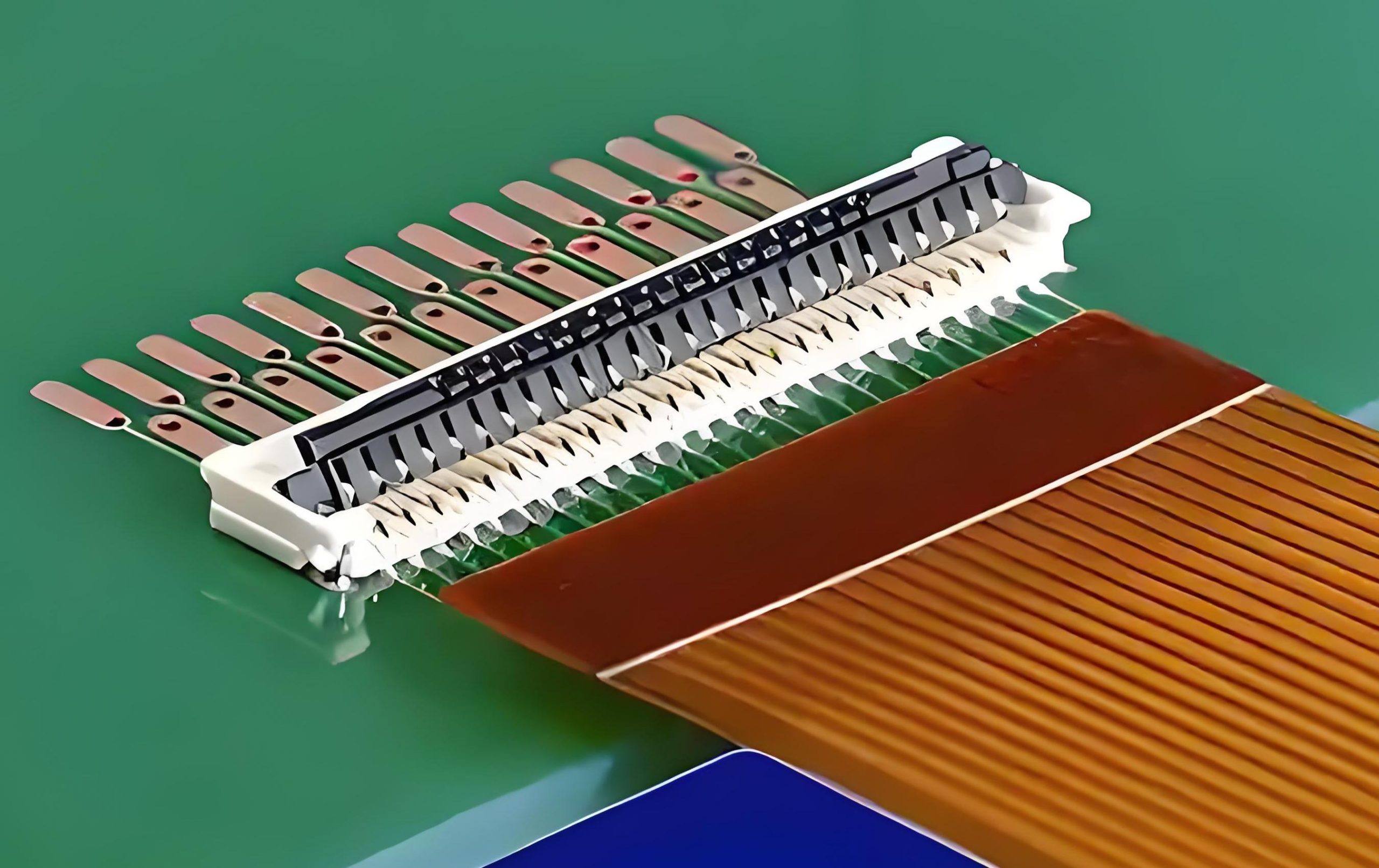
3. Repair Soldering Issues
Cold Solder/Open Circuit Repair:
- Remove old solder with desoldering braid, cleaning the pad and pin.
- Apply flux, reheat the pad with a soldering iron, and add new solder to form a smooth, bubble-free joint.
- For multi-pin connectors, use the “drag soldering” technique: pre-tin the pads, then quickly drag the iron across pins to distribute solder evenly.
Short Circuit Repair:
- Separate bridged pins with a knife or toothpick tip, clean excess solder, and re-solder.
4. Address Physical Damage
- Bent Pins: Gently straighten bent pins with tweezers, avoiding breakage. For broken pins, connect the fracture with thin copper wire (e.g., enameled wire), solder, and reinforce with silver paste.
- Cracked Housing: Repair minor cracks with epoxy glue; replace the connector if severely damaged.
- Oxidation/Corrosion: Clean pins and pads with isopropyl alcohol-soaked swabs. For severe oxidation, apply a conductive repair pen to restore conductivity.
5. Reinstall and Test
- Secure Connector: Align the connector with PCB pads, press gently with tweezers to ensure pins fully insert without tilting.
- Reinforce Soldering: Solder each pin to create strong, cold-joint-free connections.
- Functional Test: Connect external devices (e.g., power supply, signal source), use a multimeter/oscilloscope to verify signal transmission, and confirm repair success.
- Long-Term Protection: Apply a small amount of moisture-resistant adhesive (e.g., silicone) around the connector or add a protective cover to prevent dust/moisture ingress.
Why Choose EBest Circuit (Best Technology) as PCB Connector Manufacturer?
Reasons why choose us as PCB connector manufacturer:
- Fast Delivery: Offer 24-hour emergency delivery and 2-3 week standard lead times, supporting rapid prototyping of complex products to shorten time to market.
- One-Stop Service: Cover design verification, prototype development, SMT, DIP, functional testing, and automated assembly, reducing outsourcing costs.
- Quality Assurance: SO9001/IATF16949/ISO13485 certified, make sure that every process passed ISO quality inspection system.
- Cost Advantage: Reduce unit costs through bulk purchasing, lean production, and automation, with volume-based pricing to avoid low-quality low-price issues.
- Strict Quality Control: Full-process inspections include solder joint testing, impedance verification, and environmental stress screening, with regular third-party audits for process consistency.
- Technical Support: 19 years experienced team provides free DFM analysis, design optimization, troubleshooting, and responds to needs within 24 hours.
- Eco-Friendly Practices: Use lead-free solder, recyclable substrates, and energy-saving equipment to reduce carbon footprint and support green supply chains.
- Stable Supply Chain: Long-term partnerships with core suppliers, inventory forecasting, blockchain for transparent management, and reduced risk of material shortages.
- Customized Innovation: Support custom needs like special pin pitches, high-temperature materials, and waterproof/dustproof structures, with rapid prototyping for high-end applications.
Welcome to contact us if you have any request for PCB connector: sales@bestpcbs.com.