pcb
Home > Blog

Posts Tagged ‘Ims pcb definition’

IMS PCB Definition: 3 Key Focus & 80% Better Thermal
Tuesday, July 22nd, 2025

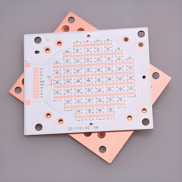
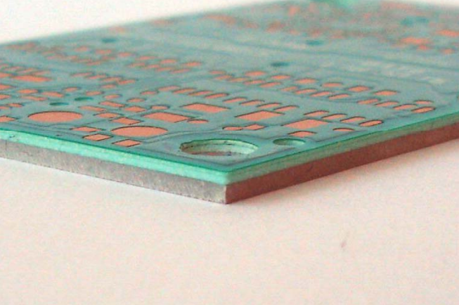
IMS PCB definitionĀ refers to a printed circuit board built on an Insulated Metal Substrate, primarily designed for excellent heat dissipation. This structure supports high-power components and keeps temperatures under control. While many boards rely on FR4, IMS stands out where thermal stress is high.

Best Technology is a top-tier IMS PCB manufacturerĀ and PCBA service provider in China. Since 2006, we have gained great first-hand experience in dealing with thermal management challenges in customers’ compact designs and providing full solutions to customers for their inadequate heat dissipation in high-power applications. Our factory has passed certifications like ISO 9001, ISO 13485, IATF 16949, AS9100D. Our factory has the full qualification to manufacture reliable IMS PCBs and PCBA to the market.

IMS PCBs stand out through their metal-core structure, thermal dielectric layer, and suitability for high-power applications—delivering up to 80% better heat dissipation than FR4. If you have any doubts about the IMS PCB definition or you require more advice from us, please make a call to +86-755-2909-1601 or send your Gerber file and special requirement details to us at sales@bestpcbs.com.
IMS PCB Definition: 3 Key Focus & 80% Better Thermal

What is IMS PCB Definition?

To understand the IMS PCB Definition, we need to break it down into three main aspects:

  1. Metal-core construction: IMS PCBs use a metal base such as aluminum or copper. This helps draw heat away from components faster than FR4 materials.
  2. Thermal dielectric layer: Between the copper circuitry and the metal base lies a special dielectric layer, usually 0.05–0.20mm thick. This layer balances electrical insulation and thermal conductivity.
  3. High-power applications: IMS PCBs are built for products that produce significant heat like LEDs, power modules, and automotive electronics. Their construction makes them dependable even under high thermal load.

When these three focus areas are optimized, the thermal performance of IMS PCB can reach up toĀ 80% better than FR4 PCBs. This is due to the metal base’s superior conductivity and the efficient stack-up structure. In short, IMS PCB is engineered for reliability in thermally demanding environments.
What is IMS PCB?

What Are the Types of IMS PCB?

There are mainly two types based on the base metal: Aluminum-based IMS PCB and Copper-based IMS PCB. IMS PCBs (Insulated Metal Substrate PCBs) come in several types depending on their structure and application needs. Each type offers unique benefits to match specific electrical, thermal, and mechanical demands. Here are the most common ones:

1. Flexible Aluminum IMS PCB
This type uses a flexible dielectric layer combined with aluminum alloys such as 5754. It can bend and conform to curved surfaces without cracking, making it ideal for wearable devices, foldable modules, or curved LED lighting. The flexibility doesn’t sacrifice thermal performance, which makes it suitable for tight and dynamic installation spaces.

2. Hybrid Aluminum IMS PCB
Hybrid types combine traditional FR4 multilayer cores (like 2-layer or 4-layer boards) with an aluminum base using thermally conductive adhesives. This structure lowers cost while still improving heat dissipation over standard FR4. It’s commonly used in RF applications or areas that need better EMI shielding along with moderate thermal control.

3. Multilayer Aluminum IMS PCB
Designed for high complexity systems, this type stacks multiple dielectric layers and may include blind vias or thermal vias. It supports dense circuit routing, power management, and thermal paths within the same board. Applications include industrial power supplies and advanced motor controls where both thermal and signal integrity are critical.

4. Through-Hole Aluminum IMS PCB
Here, the aluminum base acts as a mechanical and thermal ā€œcoreā€ for multilayer construction. Plated through holes enable either full electrical connection or insulation, depending on design. This type is well-suited for high-current modules, including automotive charging systems or power converters, where mechanical strength and efficient heat transfer are equally important.

5. Copper-Based IMS PCB
Instead of aluminum, this version uses copper (like C1100) as the metal core, offering much higher thermal conductivity—around 400 W/mĀ·K. Though more expensive, copper IMS PCBs are unmatched in heat management and are often used in extreme environments, such as high-frequency power electronics, laser systems, or high-intensity LED drivers.

What Are the Common Thicknesses of Copper Substrate IMS PCB?

Copper thickness matters in heat spreading and current capacity. Common thicknesses are:

  • 1 oz (35μm) – standard, used in most designs
  • 2 oz (70μm) – better for power and thermal needs
  • 3 oz to 6 oz – for heavy-duty applications

Choosing the right copper thickness balances cost, weight, and performance. It depends on the device’s power level and thermal load.

What is a FR4 PCB in Electrical Terms?

FR4 PCB uses a glass-reinforced epoxy laminate as the core. It is widely used due to its low cost and electrical stability. But it is not built for heat-heavy conditions. FR4 struggles when components generate high thermal energy. Let’s take a closer look at its detailed features.

1. Material and Structure
FR4 stands for ā€œFlame Retardant level 4,ā€ a UL94 V-0 rated material that self-extinguishes when ignited, enhancing electrical safety. The board is constructed by laminating layers of glass fiber for mechanical strength and epoxy resin for electrical insulation. This results in a durable, uniform substrate that supports multi-layer circuit builds.

2. Electrical Properties
One of the main reasons FR4 remains a popular choice is its reliable electrical insulation. It provides an insulation resistance between 10¹² to 10¹⁵Ω, effectively separating circuit paths.
Key dielectric characteristics include:

  • Dielectric constant (Dk) between 4.0 to 4.7 – this affects how fast signals move through the PCB.
  • Dissipation factor (Df) between 0.01 to 0.03 – indicating low signal loss, suitable for medium to high-frequency applications.
    These properties help maintain signal clarity, especially in digital and RF circuits.

3. Thermal and Mechanical Performance
FR4 PCBs generally operate within a temperature range of 130°C to 180°C, which covers most consumer and industrial electronics.
They also exhibit excellent mechanical stability, showing minimal warping under humidity or temperature fluctuations. This consistency makes FR4 a solid choice for high-precision multilayer PCB manufacturing.

4. Manufacturing and Application Benefits

  • Cost-Effective: FR4 is one of the most affordable and widely available materials. Its mature production process supports mass production with consistent results.
  • Good Workability: It can be easily cut, drilled, and etched to fit complex layouts, which speeds up prototyping and full-scale fabrication.
  • Versatile Applications: It’s used in everything from mobile phones and computers to control boards, sensors, and consumer electronics.

However, when the circuit involves high power or heat—such as in LED drivers, automotive modules, or power converters—FR4 may fall short in thermal performance. In those cases, materials like IMS offer better thermal conductivity and system reliability. IMS PCB transfers heat 80% faster than FR4 in many setups.

MaterialThermal Conductivity (W/mK)vs. FR4
FR40.1–0.5Baseline
IMS Dielectric1.0–12.08–12Ɨ higher
Aluminum Core~200400–1000Ɨ higher
Copper Core~400800–1600Ɨ higher

Why is IMS Needed?

Electronics are smaller, faster, and more powerful. This generates more heat in tighter spaces. FR4 boards can’t always manage that heat. When parts overheat, performance drops or fails entirely. IMS provides a way out. It pulls heat away from hot spots and extends product life. It keeps temperatures low and improves reliability.

Also, IMS helps reduce the size of heatsinks or external cooling. This saves space and weight, especially in automotive and lighting systems.

What Factors Affect the Quality of Thermal Separation IMS PCB?

Several key elements decide how well IMS handles heat:

  • Dielectric Layer Quality: The thinner and more thermally conductive the layer, the better the heat transfer.
  • Copper Thickness: More copper helps move heat faster.
  • Metal Base Type: Copper performs better but costs more.
  • Bonding Strength: A strong bond between layers ensures stable performance and durability.

At Best Technology, we keep strict control over each of these steps. We use advanced testing tools like TDR and thermal shock tests to validate heat performance and bonding quality.

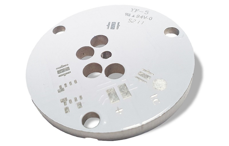
Why Choose Best Technology as Your Major IMS PCB Manufacturer?

Customers face real concerns when sourcing IMS PCBs. Some suppliers deliver inconsistent quality. Others delay shipments or use low-grade raw materials. These issues cost time and damage trust.

Best Technology solves these headaches:

  1. Traceability: Every board’s raw material can be traced through our MES system. This avoids counterfeit risks.
  2. Certifications:Ā We hold ISO 9001, ISO 13485 for medical, IATF 16949 for automotive, and AS9100D for aerospace. This proves our strict quality control.
  3. Stable Lead Time: We stick to schedules, even in tight demand cycles. Our in-house capacity and vendor network help achieve this.
  4. Engineering Support:Ā From DFM checks to prototype validation, our team gives solid advice and practical solutions.
  5. Full Solutions:Ā We support a rich product line, such as IMS PCB, MCPCB, rigid, flex, rigid-flex, ceramic PCBs, and PCBA. Whatever substrate you need, such as FR-4, high Tg FR-4, halogen-free FR-4, metal core, copper core, ceramic, Low Dk/Df (ISOLA/ Rogers), our engineers have extensive experience to suggest viable PCBs for your projects.

We also offer fast prototype runs for new designs and flexible batch sizes for scale-up plans. That gives you agility in product launch and market testing.
Why Choose Best Technology as Your Major IMS PCB Manufacturer?

In a nutshell, IMS PCB definition covers more than just structure—it’s about thermal efficiency, product lifespan, and system safety. With up to 80% better heat transfer than FR4, IMS PCBs have become the backbone of high-power, compact electronics. Choosing the right thickness, base metal, and supplier could increase your company’s competitive edge in the marketplace.

Partnering with Best Technology means fewer delays, better quality, and a team that knows what you need. We understand the real challenges you face, and we deliver real solutions. For any quotes, please contact us at sales@bestpcbs.com or call +86-755-2909-1601.

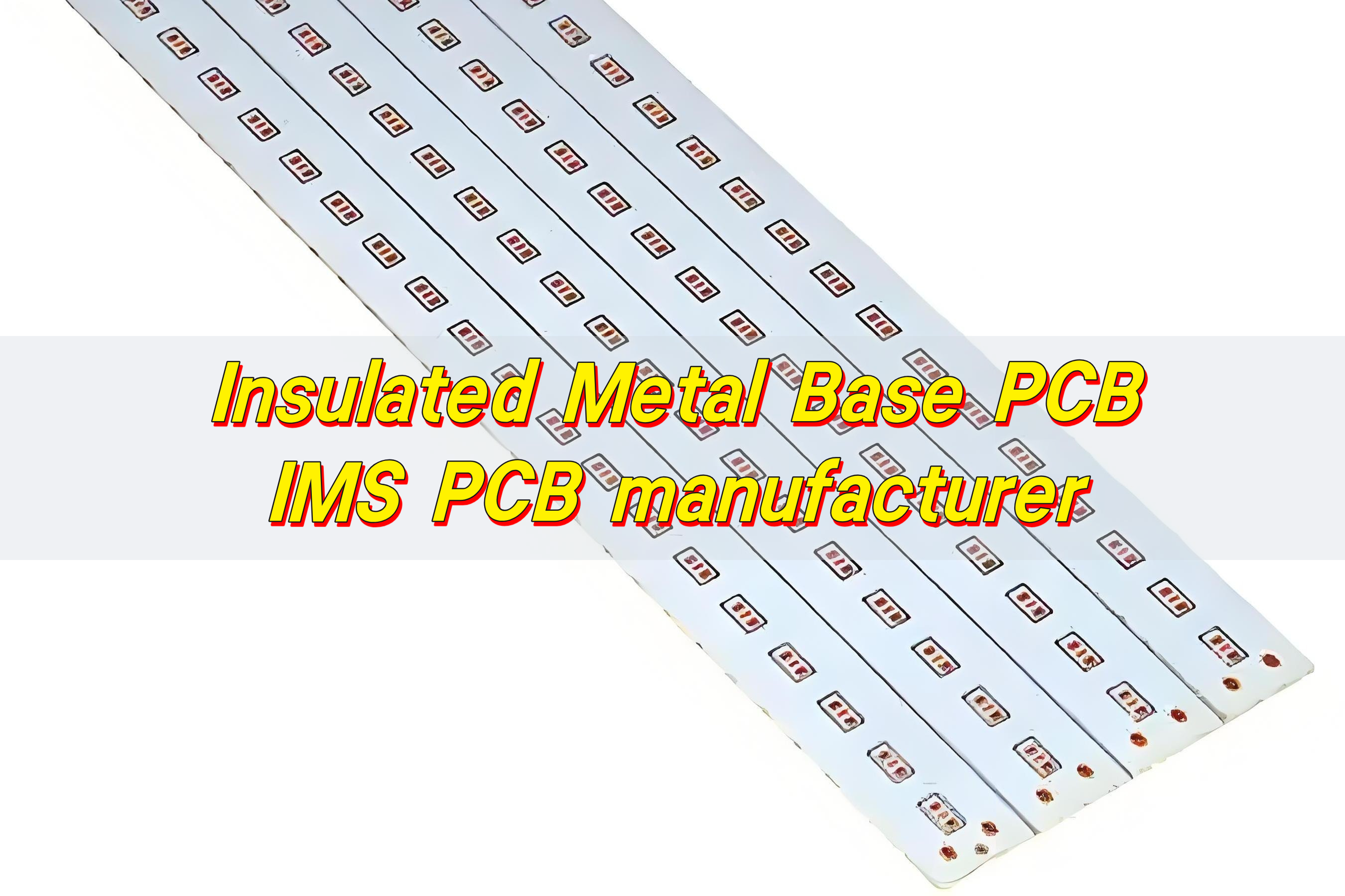
Insulated Metal Base PCB, IMS PCB Manufacturer
Monday, July 21st, 2025

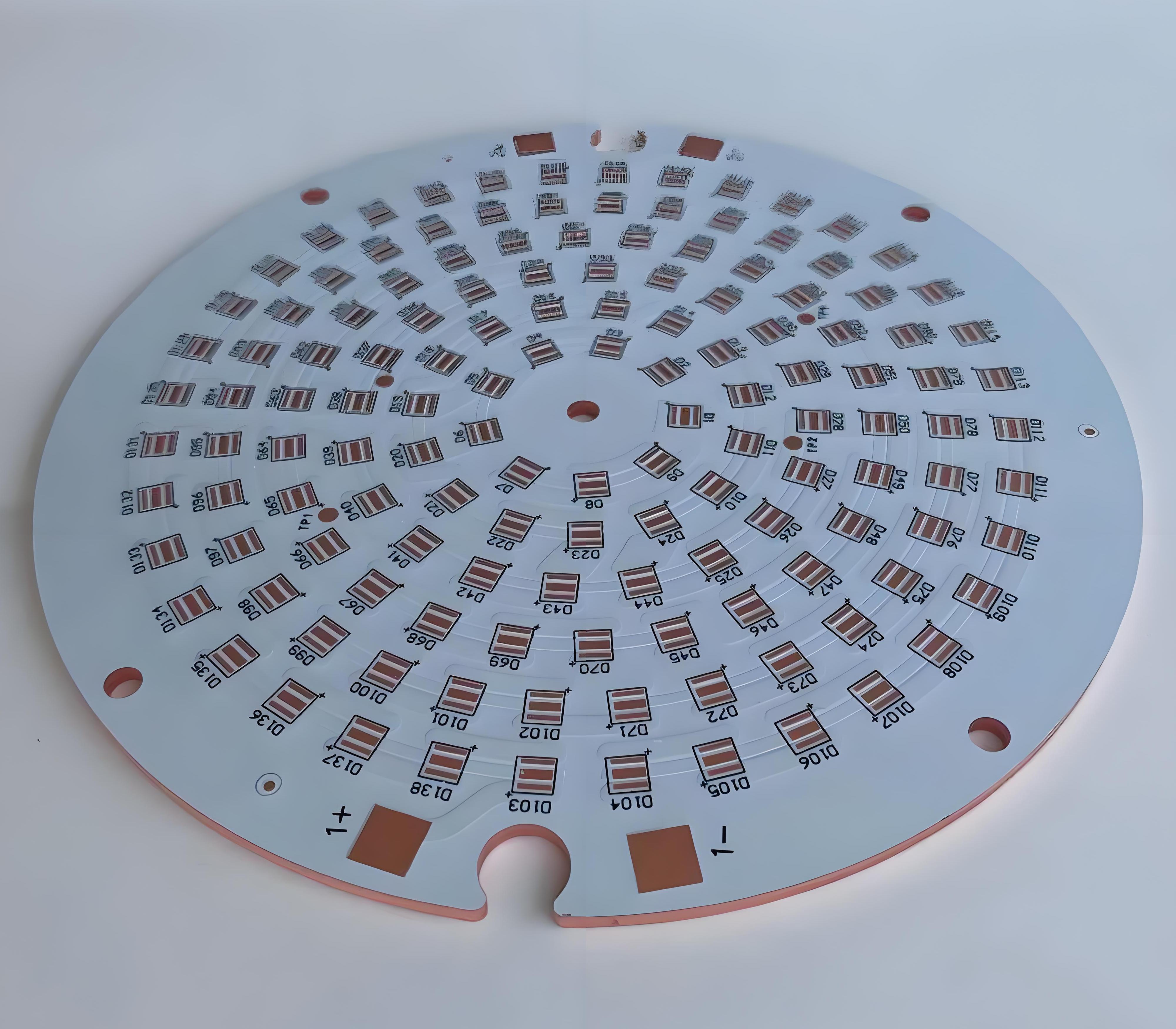
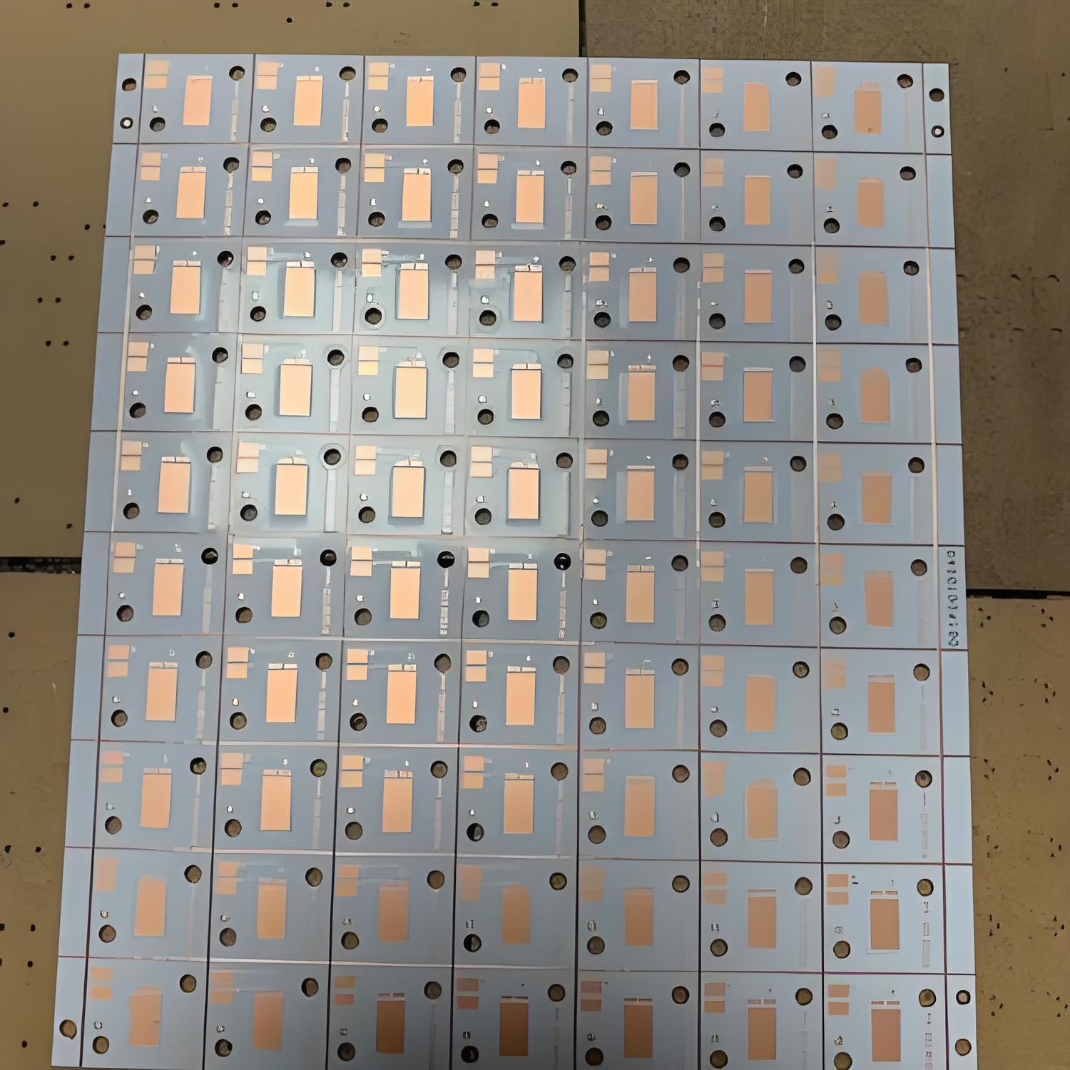
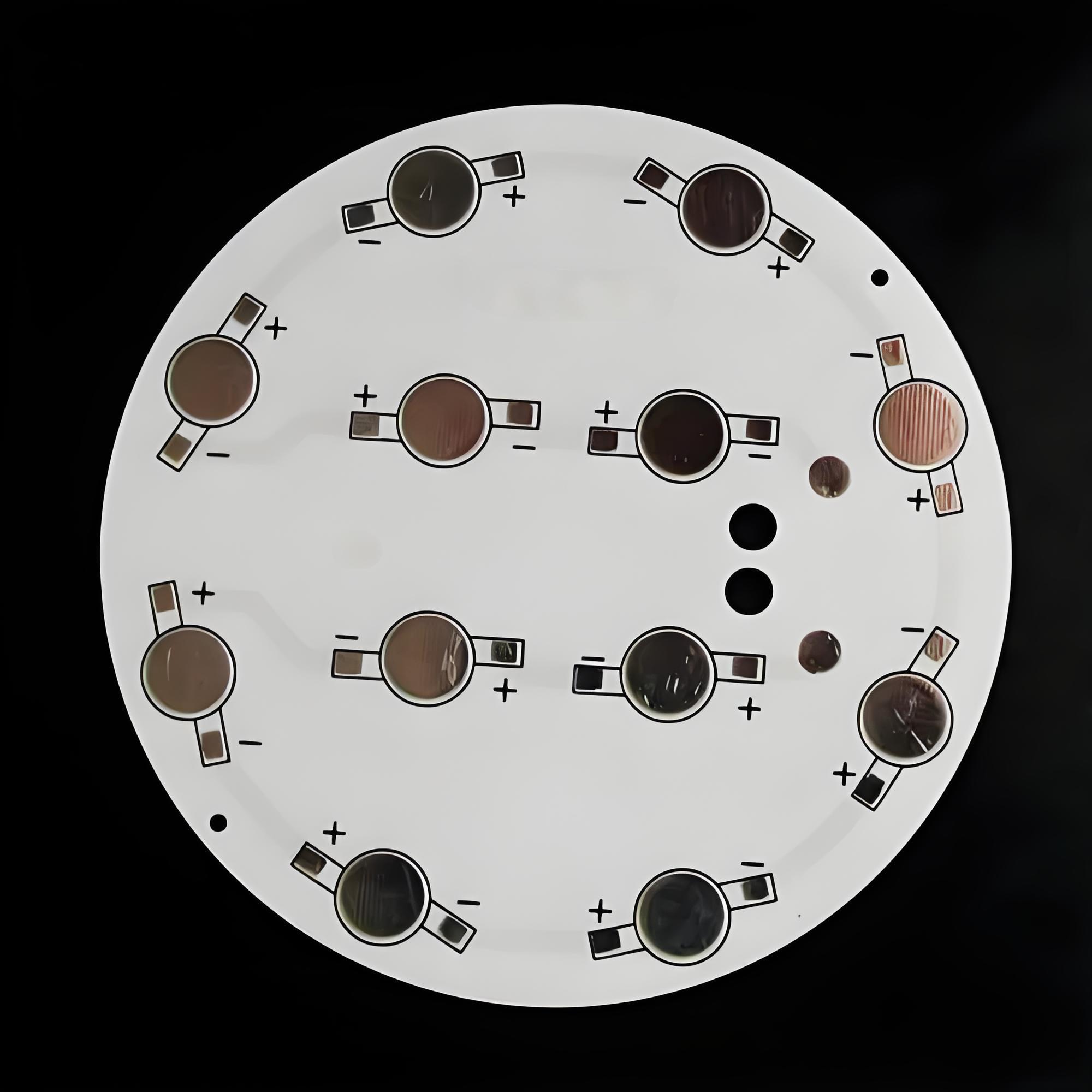
Insulated Metal Base PCB is a type of circuit board designed for high heat dissipation. It features a metal core—usually aluminum or copper—covered by a thin insulating layer and a copper circuit layer. This structure allows heat to transfer away from components quickly, making it ideal for high-power applications like LED lighting, power supplies, and automotive systems.

Insulated Metal Base PCB, IMS PCB manufacturer

What is IMS in PCB?

IMS stands for Insulated Metal Substrate. It’s a specific type of printed circuit board designed to transfer heat away from high-power components.

Unlike traditional boards made of FR4 or fiberglass, IMS PCBs have a metal base layer, typically aluminum or copper. Above this, there’s a thin dielectric insulation layer that separates the metal from the copper circuitry. This structure allows the board to carry electrical signals while efficiently pulling heat away from components.

What’s the IMS PCB definition?

In simple terms, an IMS PCB is a single-layer PCB with a metal backing that provides better thermal conductivity than standard materials.

This type of board is especially common in high-power applications like LED drivers, power supplies, automotive lighting, and industrial equipment.

The insulation layer, though thin, plays a critical role. It ensures the circuit functions properly while still allowing heat to pass through to the metal core. This sandwich-like structure is what sets IMS PCBs apart from standard designs.

What materials are used in IMS board PCB production?

Here’s what goes into a high-performance IMS board PCB:

  • Metal Base Layer: Most commonly aluminum, though copper is used in high-demand environments. Aluminum is preferred for its cost-efficiency, lightweight nature, and good thermal performance.
  • Dielectric Layer: This is the heart of heat transfer. It must be thin enough to allow thermal flow, yet strong enough to withstand voltage stress.
  • Copper Foil Layer: The circuit layer, typically 1–3 oz thick. It’s where your electronic components connect and signals travel.
  • Surface Finish: Surface treatments like ENIG (Electroless Nickel Immersion Gold) or OSP (Organic Solderability Preservatives) ensure strong soldering and prevent oxidation.
Insulated Metal Base PCB, IMS PCB manufacturer

At BEST Technology, we tailor each IMS board to your exact needs. Whether you need copper or aluminum base materials, custom thicknesses, or unique finishes, we deliver to your standards.

How does IMS manufacturing work?

The IMS manufacturing process is precise and tailored. Here’s how we do it at BEST Technology:

  • Base Preparation: We start with high-purity aluminum or copper plates. These are cleaned and prepped to remove any contaminants.
  • Lamination: A dielectric material is laminated onto the metal base. This insulation controls both heat transfer and electrical isolation.
  • Copper Cladding: A copper foil is applied on top of the dielectric. It forms the base of your circuit paths.
  • Imaging and Etching: Using UV exposure, we apply your circuit pattern. Then we etch away excess copper to leave behind only your desired traces.
  • Drilling and Plating: Holes for mechanical support or electrical connections are precisely drilled and plated.
  • Solder Mask and Finish: A solder mask is applied, followed by a surface finish that fits your assembly method.
  • Testing: Electrical testing ensures every circuit functions perfectly. Our factory performs 100% inspection before shipment.

How does IMS PCB handle heat?

The beauty of IMS PCBs lies in their thermal path. Heat from components passes through the copper trace into the dielectric layer, and from there, it’s transferred to the metal base. The base, often aluminum, quickly spreads and dissipates the heat across the board or into a heat sink.

This keeps the board cooler, even under high-power loads.

Insulated Metal Base PCB, IMS PCB manufacturer

Compared to standard FR4 boards, IMS PCBs have up to 10 times better thermal conductivity. This directly reduces component stress, avoids early failure, and boosts long-term reliability.

What are the benefits of IMS PCB?

  • Superior Heat Dissipation: IMS PCBs are engineered to manage heat—fast and efficiently.
  • Compact Design: With better thermal control, components can be placed closer together. This allows for smaller, lighter devices.
  • Longer Lifespan: Cooler components last longer. That means fewer repairs, better reliability, and a higher-quality end product.
  • High Mechanical Strength: The metal base adds stiffness and reduces vibration. Ideal for automotive, aerospace, and outdoor equipment.
  • Cost Savings Over Time: While slightly more expensive upfront, IMS boards can reduce the need for extra cooling systems.
  • High Power Density: Great for applications like LED drivers, where compact, powerful systems are a must.

In short, IMS PCBs deliver power, durability, and efficiency—the perfect trio for demanding industries.

What is an IMS board PCB used for?

IMS PCBs are extremely versatile and can be used in systems where heat and power are a concern. Common uses include:

  • LED lighting modules: Street lights, automotive headlights, stadium lighting.
  • Power electronics: Converters, adapters, power distribution units.
  • Automotive systems: Brake systems, engine control units, infotainment panels.
  • Industrial control: Motor drivers, automation panels, heavy machinery.
  • Medical devices: Imaging equipment, surgical lighting, diagnostic systems.
  • Telecom equipment: Base stations, antennas, and signal amplifiers.

These boards shine in any place where compact size and high power must coexist safely.

What is the best PCB manufacturer?

When you’re sourcing IMS boards, the manufacturer you choose makes all the difference.

BEST Technology stands out as one of the most reliable IMS PCB manufacturers in China. Here’s why:

  • Established expertise: Since 2006, we’ve focused on MCPCBs and IMS boards, delivering quality without compromise.
  • Certified reliability: We hold certifications like UL, ISO9001, ISO13485, IATF16949, and SGS—backing our quality promise.
  • Full turnkey service: From PCB design to assembly, we manage it all. This shortens lead times and streamlines your workflow.
  • Strong factory support: Our 30,000掔 plant and 229+ staff allow for large-scale production with consistent results.
  • Competitive pricing: We manage costs smartly to give you maximum value for your investment.
Insulated Metal Base PCB, IMS PCB manufacturer

Most importantly, we believe in partnerships. Our team works closely with yours, offering one-on-one assistance, custom solutions, and a 48-hour technical response policy.

Conclusion:

Whether you’re designing compact LED modules or building industrial power units, an IMS board offers the reliability and performance you need.

As a professional IMS PCB manufacturer, BEST Technology can provide trusted expertise, service and quality. With over 19 years of experience, comprehensive certifications and a customer-first philosophy, we are proud to be a reliable supplier for all your IMS board needs.

Have a project in mind? Reach out to us today at sales@bestpcbs.com

What is IMS PCB? IMS PCB Stack-up
Wednesday, June 4th, 2025

What is IMS PCB?

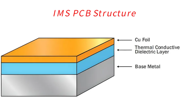
IMS PCB stands for Insulated Metal Substrate Printed Circuit Board. It’s a specialized type of PCB designed to manage heat more effectively than standard boards. At its core, an IMS board is made of three main layers: a metal base (usually aluminum), a thermally conductive dielectric layer, and a copper circuit layer on top.

This unique construction gives IMS boards exceptional heat transfer capabilities. Unlike standard FR4 boards, where heat may accumulate and degrade performance over time, an IMS PCB actively channels heat away from components and dissipates it through the metal base. This process helps protect sensitive parts and improves overall device longevity.

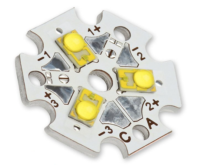
IMS PCBs are commonly used in LED lighting systems, power converters, automotive electronics, solar inverters, and industrial control systems. Any circuit that generates significant heat can benefit from the enhanced thermal management of an IMS PCB.

What is IMS PCB? IMS PCB Stack-up

Features of IMS PCB

IMS PCBs are favored in demanding applications because of their distinct advantages. Below are some of the standout features:

1. The dielectric layer in an IMS PCB has much higher thermal conductivity compared to FR4.

2. Once heat reaches the metal base, it is dispersed across a larger surface area or transferred to a heatsink.

3. The metal base not only helps with heat but also strengthens the board. This added rigidity reduces the chances of warping, especially in environments with temperature cycling or mechanical stress.

4. Components perform better and last longer when they remain within optimal temperature ranges.

5. Most IMS boards are single-sided, simplifying the layout and making them easier to manufacture. However, advanced designs may include multilayer configurations when required.

6. The metal base can also serve as a shield against EMI interference, which is useful in sensitive analog or RF applications.

Types of IMS Boards

Different IMS boards are used for different applications depending on the metal type and overall construction. Here are the three primary types:

  • Aluminum-Based IMS PCB

This is the most popular type and often the first choice for LED lighting and consumer electronics. Aluminum is lightweight, affordable, and has decent thermal performance. It strikes a balance between cost and functionality for a wide range of applications.

  • Copper-Based IMS PCB

Copper has better thermal and electrical conductivity than aluminum. These boards are used in high-end applications where superior thermal management is critical, such as power modules, solar inverters, and automotive control systems. However, copper is more expensive and heavier than aluminum.

  • Steel-Based IMS PCB

Less common but useful in environments where mechanical durability is crucial. Steel doesn’t conduct heat as efficiently as copper or aluminum but provides maximum rigidity and resistance to deformation. It’s mainly used in industrial or military electronics.

Each type of IMS PCB is selected based on the specific needs of your project. Aluminum offers a good starting point, copper pushes performance higher, and steel provides strength for the harshest conditions.

IMS PCB Stack-up

A critical element in IMS board design is the stack-up, which refers to how the different layers of the board are arranged. The typical IMS PCB stack-up includes the following:

IMS PCB Stack-up

1. Copper Layer

This is where all the electronic traces and pads are formed. The copper thickness usually ranges from 1 oz to 3 oz per square foot, depending on current requirements. It serves as the pathway for electrical signals and power.

2. Dielectric Layer

This is the thermally conductive but electrically insulating layer that separates the copper and the metal base. It’s usually made of a polymer filled with ceramic particles. The dielectric plays a vital role in transferring heat efficiently while preventing short circuits. The thickness typically ranges from 0.075 mm to 0.2 mm, with thermal conductivity from 1 to 7 W/mĀ·K, depending on material grade.

3. Metal Base

This is typically made of aluminum, copper, or steel. The metal provides mechanical support and acts as the main heat dissipation path. Its thickness usually ranges from 1 mm to 2 mm, but thicker bases are used in heavy-duty applications.

Some advanced designs may include additional dielectric and copper layers to create double-layer or multilayer IMS PCBs, though this increases cost and complexity.

How Thick is an IMS PCB?

The total thickness of an IMS PCB is influenced by the materials used and application requirements. On average, the board thickness ranges from 0.8 mm to 3.2 mm, but custom configurations are available.

Here’s a breakdown of each layer’s contribution to overall thickness:

  • Copper Layer: 35–105 µm (1–3 oz)
  • Dielectric Layer: 75–200 µm
  • Metal Base Layer: 1.0–2.0 mm (for aluminum or copper)

Applications requiring high current typically demand thicker copper layers and sometimes thicker base metals. Likewise, if better insulation is needed, the dielectric layer can be made thicker, but this may reduce heat transfer efficiency. Engineers must balance electrical, thermal, and mechanical requirements to define the most suitable thickness.

How Thick is an IMS PCB?

What is the Difference Between IMS PCB and FR4 PCB?

Though both are used in electronic devices, the differences between IMS PCB and FR4 PCB are quite substantial:

ParameterIMS PCBFR4 PCB
Full NameInsulated Metal Substrate PCBFlame Retardant Grade 4 PCB
Base MaterialMetal core (usually aluminum or copper)Fiberglass-reinforced epoxy (FR4)
Thermal ConductivityHigh (1–7 W/mĀ·K, depending on dielectric)Low (typically 0.3–0.4 W/mĀ·K)
Heat DissipationExcellent, through metal baseLimited, requires heatsinks or fans
Layer StructureUsually single-sidedCan be single, double, or multilayer
Mechanical StrengthHigh (due to metal base)Moderate (flexible but less rigid)
WeightHeavier (due to metal core)Lighter
Manufacturing CostHigherLower
ApplicationsPower electronics, LEDs, automotive, solarConsumer electronics, IoT, communication devices
Thermal ResistanceLow (better heat flow)High (poor thermal path)
Electrical InsulationThrough thermally conductive dielectricProvided by FR4 material itself
Common Copper Thickness1–3 oz1–2 oz
Typical Board Thickness0.8–3.2 mm0.6–2.0 mm
Design ComplexityLower (usually single-layer)Higher (multilayer and complex routing possible)
Price RangeMid to HighLow to Mid

What is the Thermal Resistance of IMS Board?

Thermal resistance (RĪø) refers to a material’s resistance to heat flow. In IMS PCBs, it is mainly influenced by the dielectric layer. A lower RĪø means better heat transfer and lower temperature rise.

The thermal resistance of an IMS board is calculated using:

RĪø = t / (k Ɨ A)

Where:

t = dielectric thickness

k = thermal conductivity

A = surface area

Typical values for IMS PCBs range from 0.2°C/W to 1.0°C/W, depending on materials and layout. Advanced dielectric materials with high k-values can push this number lower, helping improve performance in high-power applications.

Designers often select materials with k ≄ 3 W/mĀ·K and limit the dielectric layer to under 150 µm to achieve low thermal resistance.

Best Technology – Reliable IMS PCB Manufacturer

If you’re sourcing IMS PCBs and want consistent quality, Best Technology is your go-to IMS PCB manufacturer. We have a dedicated production line for metal-core PCBs, including aluminum, copper, and hybrid metal boards.

Why Choose Best Technology?

✅ Professional Engineering Support: Our experienced team helps optimize stackups, select dielectric materials, and improve thermal paths in your layout.

✅ ISO Certifications: We are certified with ISO9001, IATF16949, ISO13485, and AS9100D, serving a wide range of industries including medical, automotive, and aerospace.

✅ MES Traceability: Every board is tracked using our MES system to ensure complete traceability from raw materials to final shipment.

✅ Flexible Volumes: Whether you need a prototype batch or full-scale production, we offer scalable solutions.

✅ Comprehensive IMS PCB Assembly: Beyond PCB fabrication, we also offer full assembly including component sourcing, reflow soldering, inspection, and testing.

From concept to finished product, we work closely with clients to deliver high-performance IMS PCBs that meet electrical, mechanical, and thermal demands.

FAQs

1. What does IMS PCB stand for?

It stands for Insulated Metal Substrate Printed Circuit Board, a high-performance board for heat-sensitive applications.

2. Can IMS PCB be double-sided?

Yes, though less common. Double-sided IMS PCBs require more advanced fabrication and cost more, but they’re available for complex designs.

3. Is IMS PCB good for automotive systems?

Absolutely. Automotive systems generate a lot of heat and require reliability. IMS PCBs are ideal for ECUs, power converters, and headlight controls.

4. What thermal conductivity should I choose for my dielectric layer?

It depends on the heat generated. For moderate power, 1–2 W/mĀ·K is enough. For high-power LEDs or power modules, choose ≄3 W/mĀ·K.

5. How do I request a quote from Best Technology?

Send your Gerber files, stackup requirements, and assembly needs to our team, and we’ll respond with a customized quote within 24 hours.