

How to design A FPGA PCB? Discover its specification, benefits, application, and design guideline for FPGA PCB.
- Can BGA welding withstand high temperature aging?
- Why is my high-speed signal running slower and slower?
- Will multiple power supplies fight with each other?
EBest Circuit (Best Technology) Can Provide You:
- Welding perspective: Each board is X-rayed, and solder joint defects are nowhere to be hidden.
- Signal highway: From drawing board to assembly, the signal is fully escorted.
- Power traffic light: Intelligently adjust the power-on timing to prevent power supply chaos.
Welcome to contact us if you have any request for FPGA PCBA service: sales@bestpcbs.com.
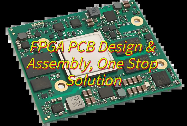
What Is FPGA PCB?
A FPGA PCB is a specially engineered printed circuit board that physically mounts and electrically integrates a field-programmable gate array semiconductor device with supporting hardware components, such as power regulators, memory units, clock sources, and input/output connectors.
This substrate features precisely routed copper traces to establish reliable electrical pathways, incorporating design elements for signal integrity in high-speed interfaces, stable multi-voltage power delivery, and efficient thermal dissipation to manage operational heat.
Once assembled, the board serves as a reconfigurable platform capable of implementing custom digital logic functions through post-manufacturing programming of the FPGA, enabling versatile applications like real-time data processing or communication bridging.
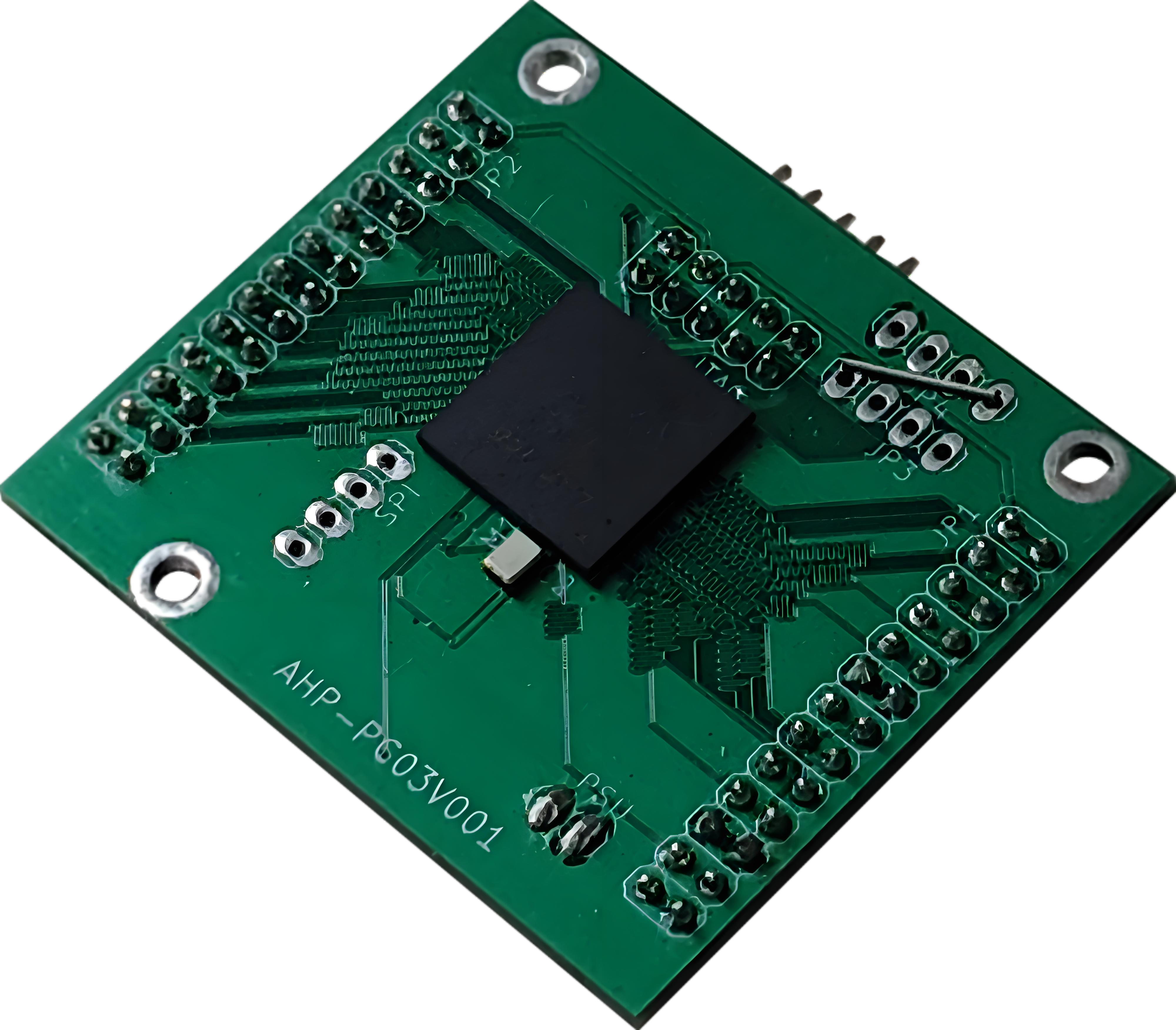
Components of FPGA PCB
1. Central Processing Unit
- Programmable logic blocks (CLBs, DSP slices).
- Configuration memory cells.
- Clock management circuits (PLLs/DCMs).
2. Power Delivery Network
- Multi-voltage regulators (1.0V core, 2.5V/3.3V I/O).
- Decoupling capacitors (0.1μF ceramic arrays).
- Power sequencing controllers.
3. Memory Subsystem
- Volatile storage (DDR3/DDR4 controllers).
- Non-volatile configuration memory (NOR Flash).
- Cache memory blocks.
4. Signal Interface Units
- High-speed serial transceivers.
- General-purpose I/O banks.
- Differential pair routing channels.
5. Support Circuits
- JTAG programming interface.
- Thermal monitoring sensors.
- Reset generation circuitry.
6. Mechanical Features
- Ball grid array (BGA) footprint
- Thermal relief patterns
- Board stiffeners (for large packages)
Why Use FPGA PCB?
- Flexible Hardware Reconfiguration: FPGAs enable post-production logic updates, allowing adaptive designs without physical hardware changes.
- Parallel Processing Capability: Customizable logic blocks execute multiple operations simultaneously, ideal for real-time signal processing.
- Low Latency for Time-Sensitive Tasks: Hardware-level processing achieves nanosecond response times, critical for industrial control systems.
- Energy Efficiency in Specialized Workloads: Dedicated circuits reduce power waste compared to general-purpose processors.
- Legacy System Modernization: Bridges outdated protocols with modern standards, extending equipment lifespan.
- Security Through Hardware Customization: Unique circuit layouts resist standardized attacks, enhancing tamper resistance.
- Rapid Iteration During Development: Immediate testing accelerates debugging versus semiconductor fabrication delays.
What Are Applications of FPGA PCB?
- Telecommunications – 5G baseband processing; Optical network conversion.
- Industrial Automation – Robotic arm control; Predictive maintenance systems.
- Medical Technology – Medical imaging acceleration; Portable diagnostic devices.
- Financial Technology – Low-latency trading systems; Real-time risk analysis.
- Aerospace & Defense – Satellite data processing; Radar systems.
- Automotive – Autonomous vehicle sensors; Vehicle network gateways.
- Consumer Electronics – Video transcoding; VR motion tracking.
- Energy Systems – Smart grid monitoring; Solar power optimization.
- Scientific Research – Physics experiments; Genomic sequencing
- IoT Infrastructure – Edge computing nodes; LPWAN base stations.
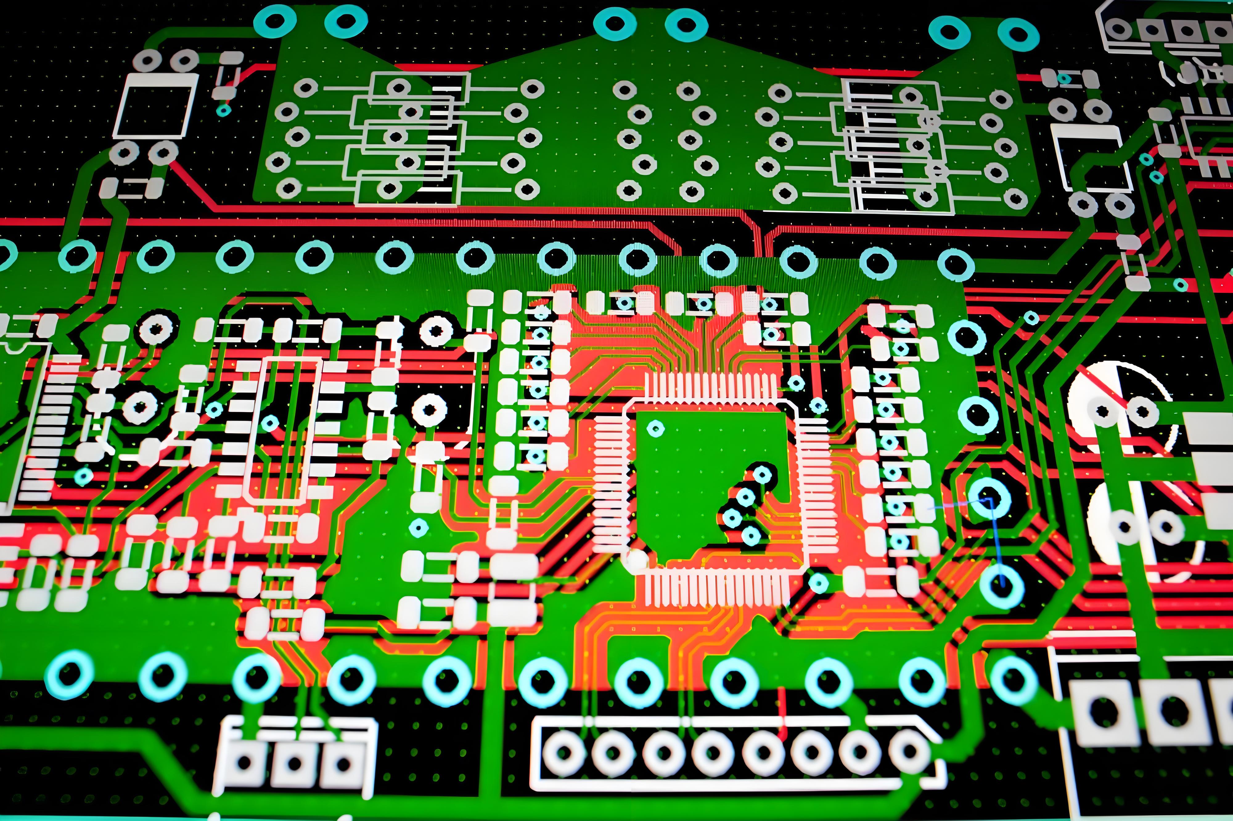
FPGA PCB Design Guidelines
Below are FPGA PCB design guidelines:
1. Layer Stack Management
- Use symmetrical stackup with adjacent power-ground plane pairs.
- Assign dedicated layers for high-speed signals with reference planes.
2. Power Delivery System
- Implement separate power islands for core, I/O and auxiliary voltages.
- Place decoupling capacitors in descending values (10μF to 100nF) near power pins.
3. Signal Routing Principles
- Maintain consistent impedance for differential pairs (+/- 10% tolerance).
- Route clock signals first with maximum ground shielding.
4. Thermal Considerations
- Use thermal vias under high-power components.
- Implement copper balancing for even heat distribution.
5. Manufacturing Compliance
- Follow 3W spacing rule for high-speed traces.
- Verify BGA escape routing meets fabrication capabilities.
6. Grounding Strategy
- Maintain continuous ground planes beneath sensitive circuits.
- Implement star grounding for mixed-signal systems.
7. Design Verification
- Perform post-layout SI/PI simulations.
- Validate timing margins with board-level models.
FPGA PCB Assembly Service – EBest Circuit (Best Technology)
- Full Turnkey Solutions – From PCB fabrication to final assembly and testing.
- High-Mix, Low-Volume Expertise – Optimized for FPGA prototyping & small-batch production.
- DFM Optimization – Early design feedback to minimize re-spins.
- Flexible Packaging – Support for advanced ICs (BGA, QFN, 01005).
- Free DFM (Design for Manufacturability) Analysis: Optimizes PCB layouts to reduce material waste, lower production costs, and avoid late-stage design revisions.
- Turnkey Solutions – Full-service PCB manufacturing from design to delivery, accelerating your product’s time-to-market.
- Superior Quality – 100% inspection on bulk orders, ensuring reliability and consistency.
- Fast Turnaround – 24-hour rapid prototyping and industry-leading production lead times.
- Stable Supply Chain – Guaranteed material availability with minimal risk of delays.
- Competitive & Transparent Pricing – No hidden costs, offering the best value without compromising quality.
Our PCBA Capabilities
| Item | Capabilities |
| Placer Speed | 13,200,000 chips/day |
| Bare Board Size | 0.2 x 0.2 inches – 20 x 20 inches/ 22*47.5 inches |
| Minimum SMD Component | 01005 |
| Minimum BGA Pitch | 0.25mm |
| Maximum Components | 50*150mm |
| Assembly Type | SMT, THT, Mixed assembly |
| Component Package | Reels, Cut Tape, Tube, Tray, Loose Parts |
| Lead Time | 1 – 5 days |
FAQs
Q1: Why does my FPGA PCB fail to boot consistently after assembly?
A1: Check solder joint integrity – BGA voids exceeding 25% cause intermittent connections. Use X-ray inspection to verify void percentage. Ensure power sequencing matches FPGA datasheet requirements (typically core voltage before I/O banks).
Q2: How to resolve signal integrity issues in 10Gbps+ transceiver channels?
A2: Route differential pairs with <5mil length mismatch and insert ground-stitching vias every 150mil near SerDes lanes. Simulate with IBIS-AMI models to validate eye diagram margins pre-production.
Q3: Why do we encounter timing closure failures despite meeting constraints?
A3: Clock skew often originates from unequal via counts in global clock trees. Balance H-tree routing with matched via transitions (typically 8 vias per branch). Add programmable delay buffers for ±50ps fine-tuning.
Q4: What causes thermal runaway in high-density FPGA designs?
A4: Inadequate copper thickness in power planes (recommend 2oz for >15A currents). Implement thermal relief patterns under BGA with 0.3mm diameter voids. Monitor junction temperature using on-die sensors via I2C.
Q5: How to mitigate EMI from high-speed memory interfaces?
A5: Apply π-type EMI filters to DDR4 DQ lines (22Ω resistors + 100pF caps). Stagger memory chip placement to break resonant cavity effects. Use shielded flex cables for off-board connections exceeding 3Gbps.