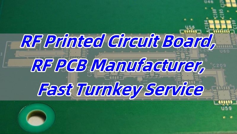
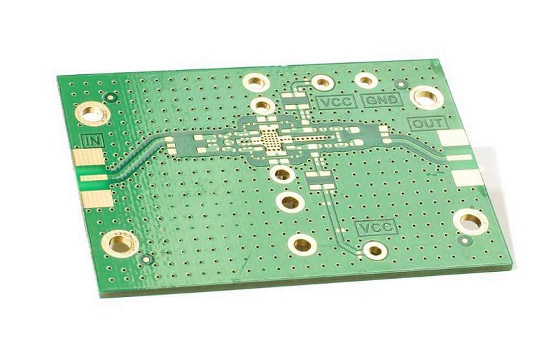
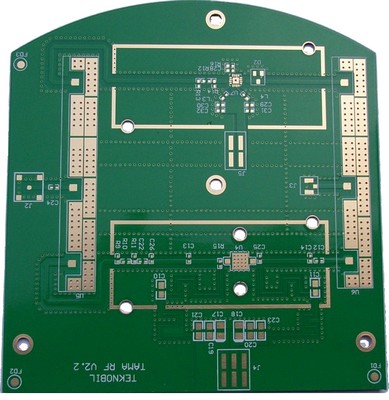
RF printed circuit board is widely used in wireless systems, communication infrastructure, and advanced radar equipment. These boards need tight control over signal paths and impedance to prevent performance issues. At EBest Circuit (Best Technology), we focus on delivering top-quality RF PCBs with full technical support and fast turnkey service.
EBest Circuit (Best Technology) is an R&D-driven RF PCB manufacturer, offering RF printed circuit board prototype, design, and assembly services. Our factory abides by ISO 9001, ISO 13485, IATF 16949, and AS9100D for every manufacturing process.  Our engineers are knowledgeable about RF printed circuit board design and adhere to the highest standards of professionalism. If any RF printed circuit board projects, just feel free to let us know at sales@bestpcbs.com at any moment.

What is RF Printed Circuit Board?
RF printed circuit board, short for radio frequency printed circuit board, is designed to handle signals in the megahertz to gigahertz range. These boards work in high-frequency environments where even minor signal losses or noise can harm system performance. Standard PCBs can’t manage such challenges, so RF PCBs follow different design and material rules.

What is PCB Material for RF Printed Circuit Board?
Material choice is key to performance. Common RF PCB materials include Rogers RO4350, Teflon, and Pyralux® AP. These have low dielectric constant (Dk) and low dissipation factor (Df), which means lower signal loss. Unlike FR-4, RF-grade materials are stable over frequency and temperature. This stability ensures clear signals even in harsh environments.
What are the RF Traces on a RF Printed Circuit Board?
RF traces are signal paths that need exact width, spacing, and length control. They carry sensitive signals that can reflect or lose energy if routing is not precise. Microstrip and stripline are two common trace styles. Engineers also use 45° angles and matched lengths for differential pairs to avoid signal mismatches and reduce interference.
How Thick is a RF Printed Circuit Board?
RF PCBs come in many thicknesses, but the choice depends on frequency, stack-up, and design needs. Typical boards are between 0.4mm and 3.2mm. âSome high-frequency applicationsâ require thinner layers and tight stack-up tolerance. Layer-to-layer alignment must also be preciseâwithin ±10μmâto reduce signal loss during travel.
What is RF Printed Circuit Board Design?
RF PCB design is much more than layout. It includes trace width calculation, layer stack-up, EMI shielding, grounding, and impedance control. Decoupling capacitors and shielding cans help reduce noise. Design rules also avoid sharp angles and encourage short, direct routing. At EBest Circuit (Best Technology), we support design analysis to prevent issues early.
How to Make an RF Printed Circuit Board?
Making an RF PCB involves several advanced steps:
- Material prep and layer alignment
- High-precision laser drilling
- Impedance-controlled trace etching
- Multi-layer lamination with ±10μm accuracy
- Plating with surface roughness below 0.5μm
- Final testing including TDR, VNA, and EMC
These steps ensure high signal integrity. At EBest Circuit (Best Technology), we also offer 24-72 hour quick-turn services to reduce your time to market. For urgent projects, we prioritize production and testing.
What is RF Printed Circuit Board Used For?
RF PCBs serve many industries:
- 5G base stations
- Radar systems
- Satellite communication
- Medical imaging
- IoT modules and RF modules
These applications need high reliability. A small error can impact performance. Thatâs why choosing the right manufacturer is critical.
Why Choose EBest Circuit (Best Technology) as Your RF PCB Manufacturer?
Many clients face issues like poor signal integrity, delayed delivery, or high cost. At EBest Circuit (Best Technology), we understand these challenges. Thatâs why we offer:
- Fast Turnaround:Â 24â72 hour quick-turn service to help speed up your launch.
- Design Support:Â Full assistance from layout review to final testing. We help reduce EMI and ensure impedance accuracy.
- Cost Optimization:Â Efficient material usage, smart supply chain, and process control cut waste and save money.
We also follow strict design rules for high-frequency applications. These include:
- Use of matched differential pairs
- Short, direct signal paths with no 90° turns
- Use of decoupling capacitors and ground shielding
- Accurate impedance matching using simulation tools

All in all, EBest Circuit (Best Technology) provides RF PCB manufacturing with quality, speed, and support. We help you avoid crosstalk, mismatched impedance, and long prototype cycles. With our experience, tools, and team, you can go to market faster. Whether you’re building IoT modules or 5G routers, weâll help you meet your RF performance goalsâon time and on budget. Reach out to us at sales@bestpcbs.com to start your RF PCB project.


