

HVAC circuit boards are the central nervous system of modern heating, ventilation, and air conditioning systems, intelligently managing operations for optimal indoor comfort. This article explores the design, function, types, and cost considerations of these critical components, providing a comprehensive guide for better climate control.
Are you frustrated with inconsistent room temperatures, frequent system breakdowns, or skyrocketing energy bills? The culprit often lies in the heart of your system—the circuit board for HVAC unit. What common issues plague these essential components?
- Compatibility Issues: HVAC universal circuit boards often fail to match specific systems.
- Early Failure: Weak designs lead to fast breakdowns and costly replacement.
- Unstable Costs: HVAC circuit board cost varies widely and unpredictably.
- Hard to Diagnose: Furnace control circuit board HVAC issues require complex troubleshooting.
- Poor Performance: Bad boards cause short cycling and inaccurate temperature control.
The solution to these pervasive problems lies in partnering with a manufacturer that prioritizes engineered design and reliability. As a specialized PCB manufacturer, we address these challenges through:
- Custom & Compatible Designs: We engineer boards that precisely match your system—not generic solutions.
- Durable Engineering: Robust materials, thermal protection, and coating ensure long service life in harsh HVAC environments.
- Transparent Cost Control: We optimize design and production to keep the control board HVAC cost predictable and manageable.
- Design for Testability: Built-in test points simplify how to test HVAC circuit board and verify low-voltage areas.
- Strict Quality Assurance: Each electronic circuit board HVAC is tested to ensure reliable and stable operation from day one.
At EBest Circuit (Best Technology), we are a professional PCB and assembly manufacturer with deep expertise in engineering robust HVAC circuit boards. Our strength lies in custom-designing boards that enhance system reliability, efficiency, and longevity. We combine advanced design software, high-quality materials, and rigorous testing protocols to deliver solutions that outperform standard offerings. For your next project, pls feel free to contact our experts at sales@bestpcbs.com.
What Is HVAC Circuit Boards?
An HVAC circuit board, often called the control board or brain of the system, is a printed circuit board (PCB) that houses the microcontroller, sensors, relays, and circuitry necessary to automate and manage all climate control operations. It interprets signals from thermostats and sensors to precisely command components like the compressor, blower motor, ignitor, and valves.
The primary functions include:
- Sequencing Operations: Starting and stopping system components in the correct, safe order.
- Safety Monitoring: Continuously checking for faults (e.g., flame failure, overheating, pressure limits).
- Communication Hub: Relaying signals between the thermostat, indoor unit, and outdoor unit.
- Diagnostic Center: Often featuring LED error codes to aid in troubleshooting.
In summary, the circuit board HVAC system relies on is fundamental for automated, efficient, and safe heating and cooling, directly impacting overall performance and energy consumption.
What Are the Types of HVAC Universal Circuit Board?
A universal HVAC circuit board is designed to replace a wide range of OEM (Original Equipment Manufacturer) boards by offering adaptable wiring and configurable settings. They provide a versatile solution for replacements.
| Type | Primary Use | Key Feature |
|---|---|---|
| Furnace Control Boards | Heating control | Ignitor + gas valve terminals |
| Air Handler/Blower Boards | Fan speed control | Multi-speed fan taps |
| AC/Heat Pump Boards | Outdoor unit control | Compressor & pressure protection |
| Fan Coil Unit Boards | Local fan/valve control | Simple motor/valve outputs |
| Combo/Multi-Purpose Boards | Broad compatibility | Multiple jumpers & DIP switches |
While HVAC universal circuit board options offer flexibility, they require proper configuration. For optimal performance and longevity, a custom-designed board is often superior.
How Does an HVAC Circuit Board Manage Heating and Cooling Operations?
The circuit board for HVAC unit orchestrates complex sequences to maintain setpoint temperatures. It acts as an intelligent switchboard, processing low-voltage signals from the thermostat into commands for high-voltage components.
Heating Cycle (Gas Furnace Example):
- Call for Heat: Thermostat closes the W terminal, sending 24V signal to the board.
- Prep & Safety Check: Board powers inducer motor to create draft. Pressure switch must close to prove draft.
- Ignition Sequence: Hot surface ignitor or spark ignitor is energized. Gas valve opens.
- Flame Proven: Flame sensor detects fire and signals the board to keep gas valve open.
- Blower Activation: After a brief delay, board energizes blower motor to circulate warm air.
Cooling Cycle:
- Call for Cooling: Thermostat closes Y (compressor) and G (fan) terminals.
- Outdoor Unit Activation: Board sends 24V signal to the outdoor unit’s AC control board.
- Compressor & Fan Start: Outdoor board engages compressor and condenser fan with proper time delays.
- Indoor Blower Activation: Indoor board simultaneously starts the blower fan at cooling speed.
By meticulously managing these sequences, the electronic circuit board HVAC system ensures safe, efficient, and responsive climate control.
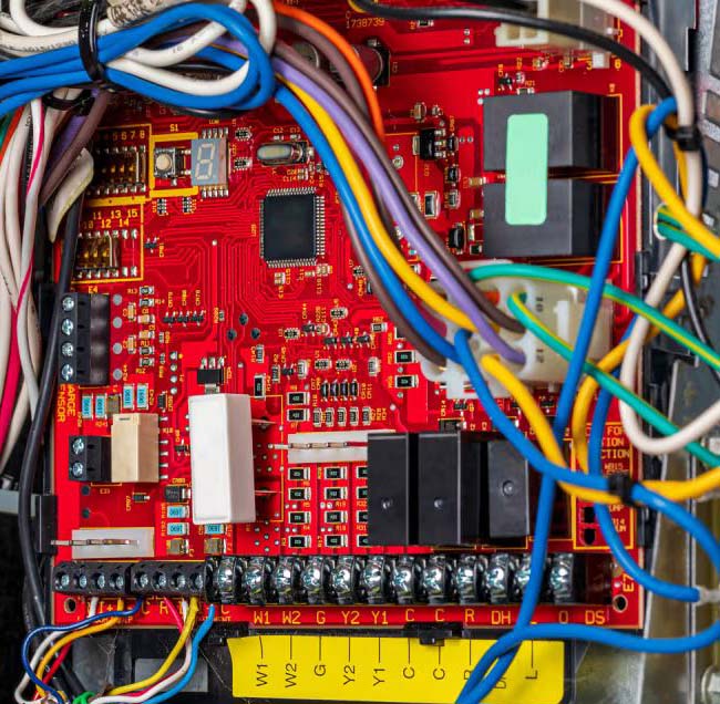
Key Components and Layout of a Circuit Board HVAC System
A well-engineered HVAC circuit board layout is critical for reliability and noise immunity. Key components are strategically placed.
- Microcontroller (MCU): The central processor. Placed centrally with clear paths to other ICs.
- Relays: Electromechanical switches for high-current devices (blower, compressor). Positioned on the board edge with robust traces to handle high current and isolate electromagnetic interference from sensitive logic areas.
- Voltage Regulator: Steps down 24VAC to 5VDC/3.3VDC for logic circuits. Located near power input with adequate heat sinking.
- Terminal Blocks: Connection points for thermostat wires (R, C, Y, W, G, etc.), power, and loads. Clearly labeled and physically sturdy.
- Sensing Circuitry: Inputs for flame sensors, pressure switches, thermistors. Includes filtering components (resistors, capacitors) placed close to the MCU input pins to prevent false readings from electrical noise.
- Status LEDs & Diagnostic Ports: For visual error codes and technician troubleshooting. Easily accessible.
- Transient Protection: Varistors (MOVs) and/or TVS diodes at power inputs to protect against voltage spikes.
A proper layout separates high-power (relays) and low-power (MCU) sections, uses a solid ground plane, and includes ample clearance/creepage distances for safety agency compliance (UL, CSA). This engineering is vital for a reliable circuit board HVAC system.
Common Designs Found in an Electronic Circuit Board HVAC System
Different systems employ specialized board designs. Here are four prevalent types:
- Single-Stage Control Boards: The most common design. Components are either fully ON or OFF. Layout is relatively simple, with one relay per major load (heat, cool, fan).
- Multi-Stage / Modulating Control Boards: For high-efficiency systems. Features multiple relays or variable speed driver circuitry to control 2-stage compressors, modulating gas valves, or ECM blower motors. Design is more complex, requiring more sophisticated MCUs and communication interfaces.
- Communicating / Networked Control Boards: Utilize serial communication (e.g., proprietary bus protocols) between thermostat, indoor, and outdoor units. Board design includes communication transceivers and enhanced processing power for optimal system orchestration and diagnostics.
- Integrated Furnace Control (IFC) Boards: Combines the furnace control circuit board HVAC function with an integrated blower motor controller (for ECM motors) on a single PCB, reducing wiring and improving reliability.
Each design prioritizes different aspects—from simplicity and cost in single-stage boards to precision and efficiency in communicating systems—showcasing how engineered HVAC circuit boards design directly enables better climate control.
How Much Does a HVAC Circuit Board Cost?
The HVAC circuit board cost is not a fixed number; it varies significantly based on several factors. Understanding these helps in budgeting for a circuit board for furnace cost or an AC control board replacement cost.
| Factor | Impact | Example |
|---|---|---|
| OEM vs Universal | OEM = Higher cost | OEM high / Universal lower |
| System Complexity | Complex = More expensive | Multi-stage > Single-stage |
| Brand | Premium models cost more | Proprietary boards higher |
| Labor & Markup | Adds to total cost | Installed total higher |
Tip: While universal boards lower upfront HVAC circuit board replacement cost, a custom-designed board from a specialist manufacturer can offer better long-term value through enhanced durability and perfect compatibility.
What Problems Commonly Occur on a Circuit Board for HVAC Unit?
Even well-designed boards can fail. Common issues include:
- Failed Relays: The most common failure. Contacts weld shut or burn out, preventing component operation. Symptom: Fan or compressor won’t start.
- Burned/Cracked Traces: Caused by power surges, short circuits, or overheating. Can interrupt critical circuits.
- Corroded Components/Connections: Due to moisture ingress or condensation. Leads to poor electrical connections and erratic behavior.
- Faulty Capacitors: Bulging or leaking capacitors, especially in power supply sections, cause voltage irregularities and board resets.
- Microcontroller (MCU) Failure: Rare, but can occur from extreme voltage spikes, rendering the board inoperable.
- Cold Solder Joints: Manufacturing defects causing intermittent connections that fail under thermal stress.
Regular maintenance and proper power surge protection can mitigate many of these issues, extending the life of your circuit board for HVAC.
How to Test HVAC Circuit Board?
Warning: Always disconnect power before inspecting. Low-voltage testing requires caution.
- Visual Inspection: Look for obvious damage: burnt areas, bulging capacitors, cracked traces, or corroded terminals.
- Check Power Input: With power restored, use a multimeter to confirm ~24VAC between R (power) and C (common) terminals.
- Check Low Voltage on HVAC Circuit Board: Simulate a thermostat call. Place a jumper from R to W (heat). You should read 24VAC between W and C. Repeat for Y (cooling) and G (fan). No voltage indicates a board fault.
- Check Continuity of HVAC Circuit Board: Power OFF. Test relays by checking for continuity between NO (Normally Open) and COM terminals when the relay is energized (simulated by applying its control voltage). Lack of continuity when energized indicates a bad relay.
- Check Output Voltages: With a call active, verify the board is sending appropriate voltage to output terminals (like for the inducer motor or gas valve).
- LED Error Codes: Refer to the board’s manual. Flashing LED patterns are the quickest diagnostic tool.
How to Choose the Right Circuit Board for HVAC?
Selecting the correct HVAC circuit board is essential for system performance, safety, and long-term reliability. Beyond matching the control logic and wiring layout, it is equally important to choose the right PCB board type—HDI, thick copper, metal-core, or ceramic—based on thermal load, current levels, and environmental demands.
1. Match the OEM Part Number
Always start with the OEM part number printed on the old board. This ensures the replacement board matches the system’s required functions, terminal assignments, and communication protocols.
2. Verify System Specifications
Before selecting a board, confirm key system characteristics:
• System type: furnace, air handler, heat pump, fan coil, PTAC
• Voltage: 24VAC control + high-voltage load requirements
• Stages: single-stage, two-stage, modulating
• Blower motor type: PSC, ECM, X13, or variable-speed
• Need for defrost logic, reversing valve control, or auxiliary heat
These system specs determine the functional type of control board required.
3. Choose the Correct Functional Control Board Type
Align board type with system application:
• Furnace control board – ignition, combustion safety, blower control
• Air handler/blower board – multi-speed indoor fan operation
• AC/heat pump board – compressor, outdoor fan, reversing valve
• Fan coil unit board – simple fan + valve control
• Communicating board – proprietary serial communication
• Integrated furnace control (IFC) – combined furnace + ECM driver
Selecting the wrong board type can cause feature loss or system malfunction.
4. Choose the Correct PCB Material and Structure Type
This is your requested addition (HDI, thick copper, MCPCB, etc.) written in precise HVAC context.
Different HVAC systems impose different electrical and thermal demands. Selecting the appropriate PCB construction type dramatically improves durability, heat resistance, and current-carrying capability.
HDI PCB (High-Density Interconnect)
Best for:
• Communicating boards
• Multi-stage or modulating systems
• Boards requiring compact layouts, fine-pitch MCUs, or dense logic circuits
Advantages:
• Higher signal integrity
• Smaller size, tighter routing
• Better reliability under vibration
Thick Copper PCB (2–4 oz or higher)
Best for:
• High-current blower relays
• Compressor control sections
• Boards exposed to heavy inductive loads
Advantages:
• Handles high current without overheating
• Reduces risk of burned traces
• More durable under surge conditions
Metal-Core PCB (MCPCB, typically aluminum)
Best for:
• Outdoor AC/heat pump control boards
• High-temperature environments
• Boards mounted near compressors or condenser fans
Advantages:
• Excellent heat dissipation
• Lower risk of thermal fatigue
• Ideal for compact designs with heat-generating components
Ceramic PCB (Alumina / AlN)
Best for:
• Extreme temperature zones
• High-reliability commercial HVAC systems
• Flame-exposed furnace compartments (in select applications)
Advantages:
• Superior thermal conductivity
• High dielectric strength
• Unmatched long-term stability
Standard FR4 PCB
Best for:
• Normal residential HVAC systems
• Indoor furnace and air handler boards
• Low to moderate thermal load applications
Advantages:
• Lowest cost
• Sufficient for most standard systems
5. Check Universal Board Compatibility (If Not Using OEM)
If using a universal board, confirm that it supports all required features:
• Terminal mapping (Y1, Y2, W1, W2, G, C, O/B)
• Heat pump configurations
• Multi-speed blower logic
• Emergency heat / auxiliary heat
• Compressor time delays
A universal board should only be chosen when it fully matches the system’s feature set.
6. Consider Build Quality and Warranty
Look for:
• High-quality relays
• Proper PCB coatings (conformal coating)
• Clear labeling and durable terminal blocks
• Strong manufacturer warranty
A longer warranty often reflects better engineering and component quality.
7. Consult a Professional When Needed
When uncertain, let a licensed HVAC technician verify compatibility. Incorrect selection can damage high-cost components such as compressors, ECM motors, or transformers.
All in all, HVAC circuit boards are the indispensable intelligence hubs that translate comfort demands into precise mechanical actions for reliable climate control. This guide has detailed their design, function, types, costs, and maintenance to empower better system understanding and decision-making.
For system integrators, OEMs, or service providers, the reliability of your product or repair hinges on the quality of this core component. EBest Circuit (Best Technology) specializes in engineering and manufacturing durable, high-performance HVAC circuit boards tailored to your exact specifications. We ensure robust designs, rigorous testing, and cost-effective solutions—from a simple furnace control circuit board to a complex multi-stage communicating system. Move beyond universal fixes to engineered reliability. Pls feel free to contact us anytime to discuss your circuit board HVAC and PCBA project needs via sales@bestpcbs.com.
FAQs
What Is HVAC PTAC Circuit Board?
A PTAC (Packaged Terminal Air Conditioner) HVAC circuit board is a specialized control board for self-contained units commonly found in hotels. It typically manages the fan motor, compressor, and heating elements (if equipped) within a single chassis, similar to a fan coil printed circuit board HVAC system but in a packaged design.
How to Check Continuity of HVAC Circuit Board?
As described in the testing section, use a multimeter in resistance (Ω) or continuity mode. Ensure power is OFF. Place probes across the component or trace you are testing. A reading near zero ohms or a beep indicates good continuity; a very high reading or OL (Open Loop) indicates a break.
How to Check Low Voltage on HVAC Circuit Board?
Set your multimeter to AC Voltage (V~) in a range above 30V. With power ON, place the black probe on the C (common) terminal and the red probe on the terminal you wish to test (e.g., W, Y, G) while simulating a thermostat call. You should read approximately 24VAC.
What Is the HVAC Circuit Board T Symbol?
The T terminal typically stands for “Transformer.” It is the 24VAC power input from the step-down transformer to the control board. You’ll usually find the other side of the transformer connected to the R (24V Hot) terminal.
Why Does My HVAC Circuit Board Have Two Y Terminals?
Two Y terminals (often Y1 and Y2) indicate support for a multi-stage cooling system. Y1 engages first-stage cooling (lower capacity), and Y2 engages second-stage cooling (higher capacity) if the thermostat determines more cooling is needed. This allows for finer temperature control and improved efficiency.