

Are double sided metal core PCB the ultimate solution for managing heat in high-power electronics? This guide details their definition, specifications, advantages, applications, prototyping steps, EBest Circuit (Best Technology)’s capabilities, and instant quotes for fast-track projects.
- Insufficient heat dissipation efficiency? Traditional PCB causes components to overheat and fail. How to break through the thermal bottleneck?
- Poor structural stability? Board deformation in high temperature/vibration environment. How to ensure long-term reliability?
- High costs? Complex processes push up prices. Can a balance between high performance and economy be achieved?
- Low design freedom? Single-sided metal substrates limit circuit layout. How to release the potential of double-sided wiring?
Thermal management innovation
- Symmetrical metal core + double-sided copper layer design, thermal resistance reduced by 40%
- Supports continuous and stable operation of 100W+ power devices
Mechanical strengthening design
- Aviation-grade aluminum alloy substrate, bending strength increased by 3 times
- Thermal expansion coefficient matches the chip carrier to avoid solder joint cracking
Cost optimization process
- Laser drilling accuracy ±15μm, reducing scrap rate to <0.5%
- Reel-to-reel production line achieves 30% reduction in batch cost
Design compatibility breakthrough
- Supports HDI+ high current hybrid design
- Provides flexible combination of 1oz~6oz copper thickness
Welcome to contact us if you have any request for metal core PCB: sales@bestpcbs.com.
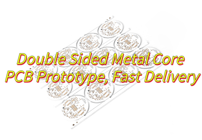
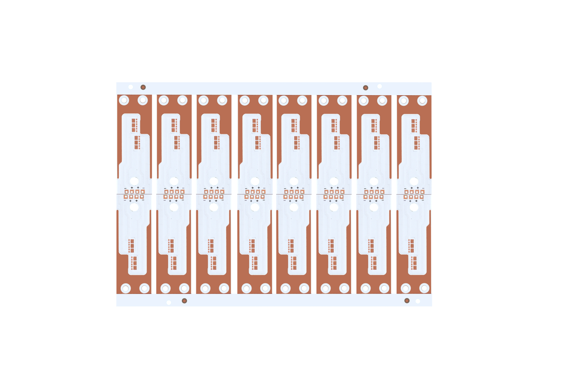
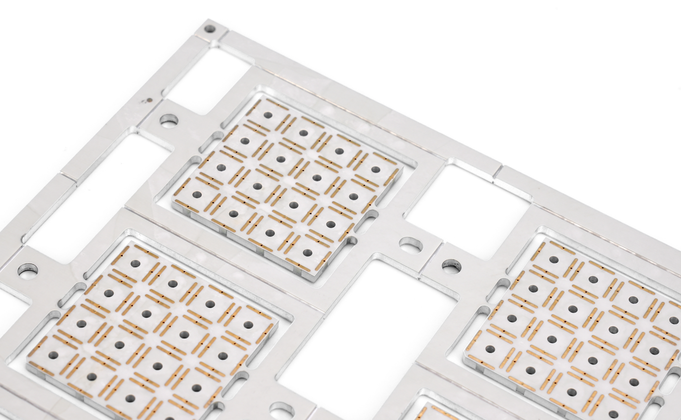
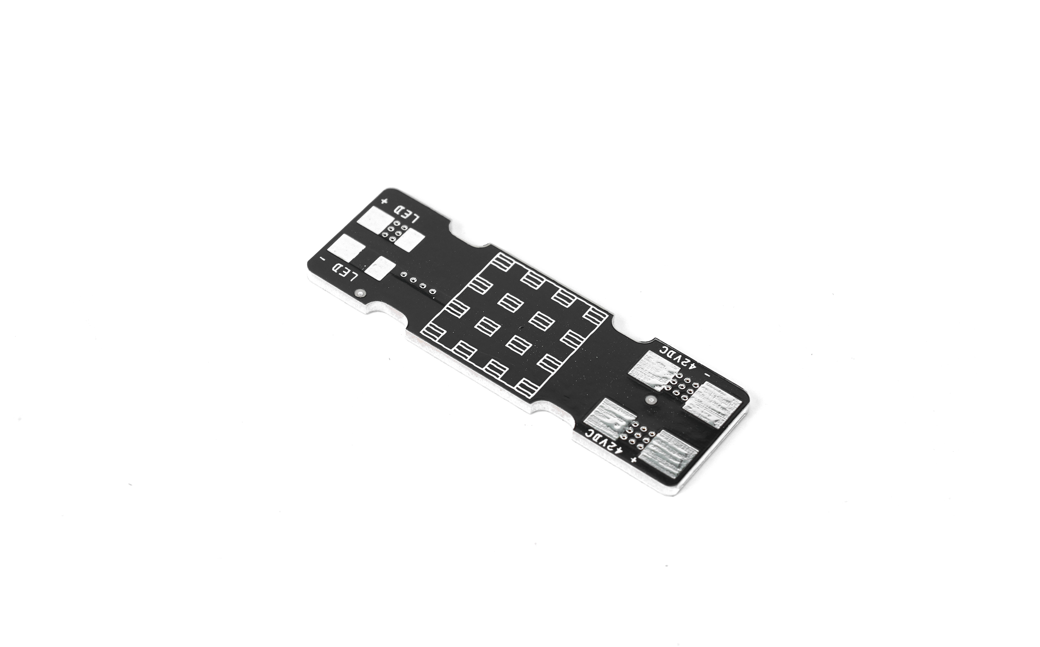
What Is A Double Sided Metal Core PCB?
A double sided metal core PCB is a specialized printed circuit board that features conductive layers on both sides of a metal substrate, typically aluminum or copper. Unlike traditional PCBs with fiberglass bases, this design integrates a metal core between the circuit layers to enhance thermal management. The metal substrate acts as a heat spreader, efficiently dissipating heat from components like LEDs or power electronics, while the dual-sided circuitry allows for more complex routing in compact spaces.
The construction involves insulating dielectric layers bonded to both sides of the metal core, with plated through-holes (PTH) enabling electrical connections between the top and bottom circuits. This structure maintains mechanical stability under thermal stress, making it ideal for high-power applications where temperature control is essential. Double sided metal core PCBs are widely used in automotive lighting, industrial power systems, and high-brightness LED arrays due to their durability and superior thermal performance.
Specifications of Double-sided Metal Core PCB
Here are the technical specifications for double-sided metal core PCBs:
Base Material
- Metal core options: Aluminum (1.0–5.0mm) or Copper (0.8–3.0mm)
- Standard alloys: Aluminum 5052/6061, Copper C11000
Dielectric Layer
- Thickness: 50–200μm
- Thermal conductivity: 1.2–3.0 W/mK
- Dielectric strength: ≥3kV DC
Copper Layers
- Weight: 35–140μm per side
- Minimum trace width/spacing: 0.1mm/0.1mm
Through-Hole Technology
- Via diameter: ≥0.15mm (mechanical), ≥0.3mm (laser)
- Plating thickness: 25–50μm
Thermal Performance
- Thermal resistance: 0.5–3.0°C/W (depending on design)
- Max operating temperature: 130–150°C
Mechanical Properties
- Flatness tolerance: ≤0.5% of board size
- Bend radius: 5× board thickness (aluminum), 3× (copper)
Surface Finishes
- Options: ENIG (0.05–0.15μm Au), HASL, OSP, Immersion Silver
Typical Applications
- High-power LED modules (50–200W)
- Automotive power electronics
- Industrial motor drives
Special Features
- Supports SMT and through-hole components
- Compatible with FR-4 lamination for hybrid designs
- UL94 V-0 flame rating available
Design Constraints
- Minimum annular ring: 0.075mm
- Maximum board size: 600×450mm
- Layer registration tolerance: ±0.05mm
Advantages of Double Sided MCPCB
- Better Heat Dissipation - Cools components 15-25% more effectively than single-sided designs by spreading heat through both metal sides.
- Higher Component Density - Fits 30-40% more parts by using both board surfaces without overheating.
- Stronger & Flatter – Stays straighter under heat (under 0.3mm bend at 150°C) due to balanced layers.
- Handles More Power – Carries 50% higher electric current by distributing load across two copper layers.
- Saves Space – Replaces separate heatsinks, making devices 2-4mm thinner.
- Flexible Wiring – Works with standard and tiny vias (down to 0.15mm) for circuit connections.
- Cost Efficient – Cuts system costs 20-35% by combining thermal and circuit functions in one board.
Application of Double Sided Metal Core PCB
- High-power LED lighting – Dual-sided component integration with thermal management
- Automotive power systems – Motor controllers and converters requiring vibration resistance
- RF amplifier designs – Compact signal processing with heat dissipation benefits
- Solar energy inverters – Three-phase power conversion with direct cooling
- Industrial sensors – Multi-layer circuitry for temperature-sensitive applications
- Medical devices – Precision thermal control in imaging systems
- Aerospace electronics – Compact avionics with thermal cycling durability
How to Make A Double Sided Metal Core PCB Prototype?
How’s how to make a double sided metal core PCB prototype:
1. Material Selection
- Choose aluminum or copper alloy as the metal core, with thickness tailored to thermal and mechanical needs.
- Select dielectric layers with high thermal conductivity (e.g., ceramic-filled epoxy) to insulate while transferring heat.
2. Circuit Layer Fabrication
- Etch copper foil on both sides using photolithography: apply photoresist, expose patterns, and chemically etch excess copper.
- Rinse and dry etched panels to avoid residue affecting adhesion.
3. Lamination Process
- Stack layers: metal core, dielectric, and etched copper circuits.
- Use vacuum-assisted hot press to bond layers, ensuring dielectric fills gaps and adheres uniformly.
4. Drilling & Plating
- Drill via holes with CNC equipment, aligning positions to connect top and bottom circuits.
- Plate holes with electroless copper followed by electrolytic copper to create conductive pathways.
5. Surface Finishing
- Apply surface treatment (e.g., HASL, ENIG) to protect exposed copper and enable soldering.
- Inspect finish quality under microscopy to avoid defects.
6. Electrical Testing
- Conduct continuity and isolation tests using flying probe or bed-of-nails systems.
- Verify thermal performance by simulating operational conditions (e.g., power load, ambient temperature).
7. Prototyping & Assembly
- Cut individual boards from the panel and solder sample components.
- Power up the prototype to test functionality, thermal behavior, and mechanical stability.
Double Sided Metal Core PCB Manufacturer – EBest Circuit (Best Technology)
- Thermal Management Excellence – Our 2.0mm aluminum core reduces operating temps by 25-30°C, solving overheating in LED/high-power applications.
- Rapid Prototyping – 24-hour turnaround for double-sided MCPCB samples (industry avg: 3-5 days).
- Cost-Efficient Scaling – 15% lower batch pricing for 500+ units without sacrificing quality.
- Global Material Sourcing – Japanese aluminum substrates + Isola dielectrics for stable high-frequency performance.
- Turnkey Solution – End-to-end service (design → assembly → testing) to simplify your supply chain.
- Free DFM Analysis – Prevent costly errors early with expert design optimization.
- 24/7 Engineering Support– Delivering round-the-clock technical consultation with immediate response to design changes or urgent requirements
- Precision Tolerance – ±0.1mm laser drilling ensures perfect alignment for double-sided designs.
- Environmental Durability – Passes 96-hour salt spray and 1000 thermal shock cycles (-40°C to +150°C).
Double Sided Metal Core PCB Capability
| Base material: | Aluminum/Copper/Iron Alloy |
| Thermal Conductivity (dielectrial layer): | 0.8, 1.5, 2.0, 3.0 W/m.K. |
| Board Thickness: | 0.5mm~3.0mm(0.02″~0.12″) |
| Copper thickness: | 0.5 OZ, 1.0 OZ, 2.0 OZ, 3.0 OZ, 4.0 OZ, 5.0 OZ |
| Outline: | Routing, punching, V-Cut |
| Soldermask: | White/Black/Blue/Green/Red Oil |
| Legend/Silkscreen Color: | Black/White |
| Surface finishing: | Immersion Gold, HASL, OSP |
| Max Panel size: | 600*500mm(23.62″*19.68″) |
| Packing: | Vacuum/Plastic bag |
| Samples L/T: | 10~15 Days |
| MP L/T: | 12~15 Days |
Instant Quote
Double sided metal core PCBs deliver robust thermal management and higher wiring density for complex circuits, with conductive layers on both sides interconnected by vias to support demanding high-power applications. They excel in environments requiring enhanced reliability, such as LED lighting and automotive electronics, by preventing overheating and ensuring stable performance. For precision manufacturing with rapid prototyping and instant quotes, please contact EBest Circuit (Best Technology) to submit your inquiry today: sales@bestpcbs.com.