

A cold solder joint is one of the most common failure mechanisms in electronics assembly, yet many technicians and engineers encounter it long before fully understanding its root behaviors. When a joint lacks proper heat, does not wet the copper pad, or cools in an uncontrolled manner, the resulting connection becomes unstable. It may pass initial testing, but its long-term reliability declines.
Because modern electronics demand consistent performance—whether in consumer devices, industrial controllers, automotive modules, or medical PCB assemblies—recognizing and preventing cold solder joints remains essential for every design or manufacturing team.
What Is a Cold Solder Joint?
A cold solder joint is a solder connection that forms without reaching the proper temperature for the solder alloy to fully melt, flow, and wet the surfaces. Instead of a smooth, solidly bonded joint, the resulting structure becomes dull, grainy, or cracked. The term “cold” comes from the fact that these joints never reach the temperature required to create a metallurgical bond between the solder and the copper pad or component lead.
In practical terms, the solder solidifies before forming a stable interface. Instead of integrating with the metals it is meant to join, it merely sits on top of the surfaces. The joint may appear attached, but internally it lacks the uniform crystalline structure that defines a reliable connection.
In manual soldering, cold joints often happen due to inconsistent technique. In automated SMT production, they typically arise from incorrect reflow profiles, insufficient preheat, or contaminated pads that prevent proper wetting. Because of these variables, avoiding cold solder joints requires both strong process control and clean material handling.

Do Cold Solder Joints Still Work?
A cold solder joint may still work, at least at the beginning. This is where confusion begins for many technicians. The joint may pass functional testing, power-on checks, or a quick continuity test. Because the mechanical bond is weak and the electrical interface incomplete, the behavior becomes intermittent.
A device with cold joints may operate well in a static environment but become unstable when exposed to:
- Temperature swings
- Vibration or shock
- Thermal expansion during operation
- Humidity or oxidation
- Long-term cycling
While a cold joint can conduct current, it does so inconsistently, and usually with higher resistance. Over time, micro-cracks grow, creating open circuits or signal noise. For that reason, cold solder joints are considered functional only by coincidence, not by design.
Cold Solder Joint Symptoms
Cold solder joints have predictable symptoms. Engineers often rely on these visual or electrical clues to locate the root cause of a circuit failure:
- Dull, Frosty, or Grainy Surface
- Irregular Shape or Incomplete Wetting
- Visible Cracks or Rings
- Intermittent Performance
- Increased Resistance
- Movement When Touched
- Failure Under Thermal Stress
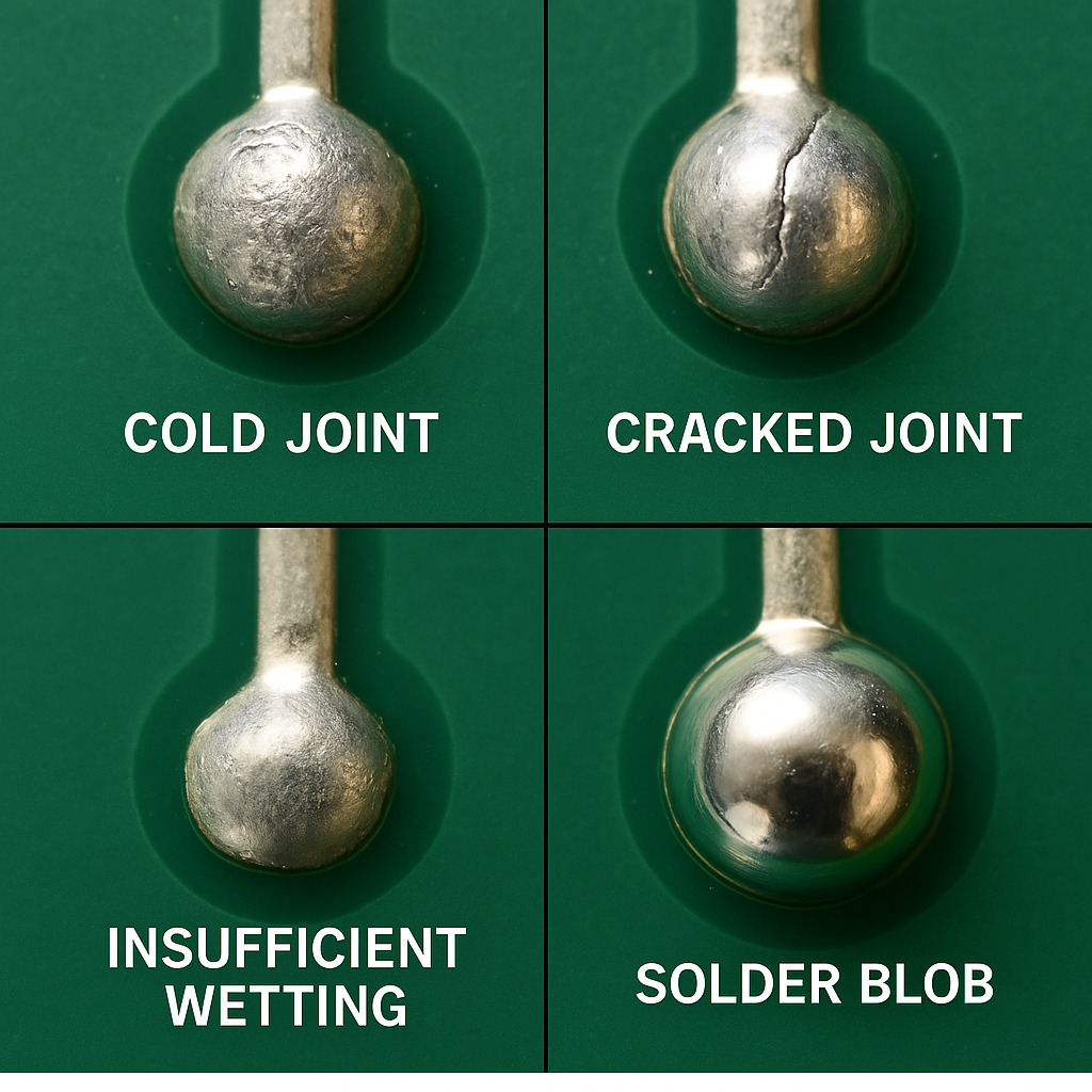
These symptoms are reliable indicators during repair, inspection, or failure analysis.
What Is the Difference Between a Cold Solder Joint and a Good Solder Joint?
A good solder joint forms a solid intermetallic bond between the solder, the copper pad, and the component lead. It exhibits a smooth, shiny, and uniform shape with complete wetting.
Comparing both joints helps clarify the contrast:
| Aspect | Cold Solder Joint | Good Solder Joint |
| Appearance | Dull, grainy, frosty surface | Smooth, shiny, uniform surface |
| Wetting Behavior | Poor wetting; solder sits on top of pad/lead | Complete wetting across pad and lead |
| Mechanical Strength | Weak bond; prone to cracking or movement | Strong bond with stable mechanical support |
| Electrical Performance | Higher resistance; intermittent continuity | Low resistance; stable, consistent conductivity |
| Reliability | Unpredictable; often fails under vibration or heat | Long-lasting; passes thermal and vibration stress |
| Internal Structure | Incomplete metallurgical bond; voids possible | Proper intermetallic layer with solid structure |
| Common Causes | Insufficient heat, oxidized surfaces, poor flux activity | Correct temperature, clean pads, controlled soldering |
| Inspection Result | Rejected under IPC standards | Acceptable and compliant with IPC criteria |
| Typical Symptoms | Intermittent signals, device resets, heat spots | Normal operation with steady performance |
| Corrective Action | Reheat, add flux, reflow or resolder | No action required |
How to Identify a Cold Solder Joint?
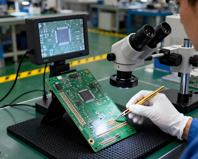
Identifying cold solder joints requires a combination of visual inspection, tactile testing, and electrical measurement. Here are the most common methods:
- Visual Inspection
Under a microscope or magnifying lamp, look for dull surfaces, cracks, uneven shapes, or insufficient solder spread. Most cold joints are visible to a trained eye.
- Continuity and Resistance Testing
Using a multimeter, check whether current flows consistently. Cold joints may pass continuity tests but show higher resistance.
- Thermal Stress Testing
Heating or cooling the PCB may cause the joint to open or reconnect.
- X-ray Inspection (for BGA or QFN)
In high-density packages, internal cold joints appear as voids, incomplete wetting, or irregular solder shapes.
- Mechanical Movement
Applying gentle pressure can reveal looseness in through-hole components.
Early identification is essential in avoiding expensive rework or device failure.
Are Cold Joints Acceptable?
Cold solder joints are not acceptable in any professional electronics assembly environment. Industry standards such as IPC-A-610 define cold joints as defects requiring correction. Even in hobby projects, cold joints degrade reliability.
There are no scenarios where cold joints are intentionally tolerated. Any sign of incomplete wetting or insufficient flow must be corrected immediately. or mission-critical industries such as:
- Medical
- Automotive
- Industrial automation
- Aerospace
- IoT
- Telecommunications
cold solder joints represent unacceptable risk.
What Causes a Cold Solder Joint?
Cold solder joints form due to several common process issues. Understanding these causes helps prevent recurrence.
1. Insufficient Heat
If the soldering iron does not fully heat the pad and lead, wetting cannot occur.
2. Contaminated or Oxidized Surfaces
Residue, dust, oxide layers, or aged plating can block wetting.
3. Incorrect Solder Alloy or Temperature
Low heat settings, mismatched solder types, or incorrect thermal profiles lead to poor flow.
4. Poor Flux Activity
Flux cleans surfaces. Weak or expired flux prevents proper bonding.
5. Movement During Solidification
If the lead moves before the solder cools, a cold joint forms.
6. Inconsistent Reflow Profile
In SMT production, a poorly tuned reflow oven produces cold joints, especially on large thermal pads or ground planes.
7. Manual Soldering Technique Errors
Rushed or inconsistent soldering practices can create joints that never heat sufficiently.
What Are the Risks of Cold Joints?
Cold solder joints introduce multiple failure modes, including:
1. The device may work partially, only under specific temperature or vibration conditions.
2. Higher resistance destabilizes signals, especially in RF or high-speed digital designs.
3. Poor conductivity forces current to generate heat, stressing components.
4. Cold joints often degrade quickly in real-world conditions.
5. In power electronics, cold joints increase the risk of arcing or thermal runaway.
These risks emphasize the need for controlled soldering conditions, proper inspection, and strict quality assurance.
How to Avoid Cold Solder Joints?
Preventing cold solder joints requires strong process management, skilled operators, and adherence to IPC and manufacturer guidelines.
1. Ensure Proper Heating
Heat both pad and lead evenly. Maintain appropriate soldering temperatures for the chosen alloy.
2. Use High-Quality Solder and Fresh Flux
Materials is important, Fresh flux ensures clean surfaces and stable wetting.
3. Clean and Prepare Surfaces
Remove oxidation, oil, or contamination before soldering.
4. Maintain Stable Reflow Profiles
For SMT production, program time-temperature profiles to match the alloy. Adjust for heavy copper or large thermal pads.
5. Avoid Movement During Cooling
Secure components so solder can solidify without vibration.
6. Use Proper Tools
ESD-safe irons, clean tips, good tweezers, and inspection magnification help ensure accuracy.
7. Follow IPC Guidelines
Standards such as IPC-A-610 and IPC-J-STD-001 provide industry-accepted criteria for solder quality.
Understanding the distinction between a cold solder joint and a properly formed one helps engineers and technicians diagnose failures accurately. A cold solder joint appears dull, weak, and inconsistent, while a good joint is smooth, shiny, and electrically stable. The difference directly affects device performance and lifespan.
As electronics continue shrinking and integrating more complex components, the need for reliable soldering becomes even more critical. Whether you are working with prototype boards, high-density PCBs, or mission-critical assemblies, eliminating cold joints should always be a priority.