Archive for September, 2021

The function of solder mask layer on the PCB Board.

Monday, September 20th, 2021

At last time, we shared a blog talking about Why most of the PCB boards are green?. Believe you’ve known the reasons for why most of solder mask colors are green.

Today, let’s share something about the function of solder mask on the Printed Circuits Boards.

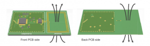
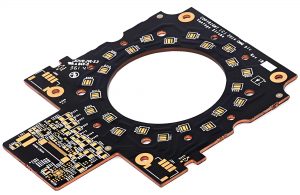
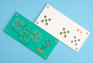
The solder mask layer is designed mainly to prevent the PCB copper foil from being directly exposed to the air and play a role in protecting the PCB surface, which is also to prevent the area that should not be soldered from being soldered.

PCB Solder mask

As we know that almost all the PCB need to do the assembly, which need to go through the reflow soldering while the assembly, and solder mask plays an important role during control of the reflow soldering process.

Here is a summary for what solder mask roles played on the board:

(1) Prevent physical disconnection of conductor circuits on the circuits board;

(2) In the welding process, solder mask can prevent short circuit caused by bridging;

(3) solder mask can reduce copper pollution to the soldering trough;

(4) Print solder mask on the PCB can prevent insulation deterioration and corrosion caused by external environmental factors such as dust and moisture;

(5) Solder mask are with high insulation; it is possible to increase the density of the circuit.

Red solder mask

In terms of solder mask material, it must be used through liquid wet process or dry film lamination.

Dry film solder mask materials are supplied in a thickness of 0.07-0.1mm (0.03-0.04″), which can be suitable for some surface mount products, but this material is not suitable for PCBs with tighter pitches.

You may also like

Why choose MCPCB rather than FR4 PCB for high power LED?

Monday, September 20th, 2021

Compared to conventional LED, high-power LED consume more electricity and require higher currents, but the heat generated in the end cannot be dissipated in time through the ordinary FR4 CPB. And there will be some failures when the heat from a LED is not properly removed, the LED’s light output is reduced as well as degradation when the heat remains stagnant in the LED package.

So if the PCB requires fast cooling, it’s better to use a metal base rather than a traditional FR-4 substrate. The typical LED MCPCB is a single circuitry layer copper foil which is bonded to a layer of thermally conductive dielectric material which is bonded to a thicker layer of metal like Aluminium or Copper base, the purpose of a MCPCB is to efficiently remove the heat from all topical IC’s (not just LEDs). Following are the comparison between FR4 PCB and MCPCB for your reference.


1. Thermal Dissipation

FR4 has low thermal conductivity, typically around 0.3W/m.K, while MCPCB has higher thermal conductivity, ranging from 1.0-7.0W/m.K. MCPCB transfer heat 8 to 9 times faster than FR4 PCB, the dielectric layer must be very thin to create the shortest path from the heat source to the supporting metal plate, its thickness is normally between 0.003 and 0.006 inches.

As an example, consider that a test conducted on an MCPCB with integrated 1W LED showed how its temperature remained pretty close to the ambient temperature of 25°C, while the same power LED mounted on a FR-4 board reached a temperature 12°C higher than the ambient one.

2. Better Strength and Stability

Since high power LED chips are usually assembled directly on the PCB, these LEDs can create stability and reliability problems for the circuit. Without adopting the right technique, heat dissipation can hinder the performance of electronic devices that operate at high power. The use of metal PCBs in these applications effectively solves this problem. In addition to ensuring a high durability, aluminum is very light, and adds strength and resilience to the printed circuit board without causing an increase in weight.

3. Dimensional Stability

The size of a metallic printed circuit board remain more stable, as environmental conditions vary, than that of a PCB made with traditional materials, such as FR-4. Subjected to a heating process from 30°C to about 150°C, PCBs with metal layers (such as aluminum) have undergone a very small variation in size, ranging from 2.5% to 3.0%.

If you have other questions about MCPCB, welcome to contact us.

You may also like

Ceramic PCB is suitable for UVC-LED

Wednesday, September 8th, 2021

Due to COVID-2019, UVC-LED is becoming more and more popular.

The wavelength of UVC-LED is 100-275nm, 265 nm is the best!

Why UVC-LED is becoming more and more popular?

Because UVC-LED has a lot of advantages for sterilization.

High efficiency: The UVC segment ultraviolet light emitted by UVC-LED generally kills bacteria and viruses within a few seconds.

Extensive bactericidal effect: UVC-LED can kill a lot of bacteria.

Safety and environmental protection (without mercury): The most obvious advantage of UVC-LED devices over traditional mercury-excited ultraviolet lamps is that the germicidal light source does not contain mercury or heavy metals, and is simple to operate, safer and more reliable.

Small size, flexible design, easy installation: UVC-LED devices are small in size, and the sterilization device is flexible in design. It can be used in small spaces where traditional ultraviolet mercury lamps cannot be used. It is more in line with the future development trend of high efficiency, small size and integration.

Why ceramic PCB is suitable for UVC-LED?

Because UVC-LED is sensitive to heat.

Due to the low external quantum efficiency (EQE) of UVC-LEDs, only about 1-3% of the input power is converted into light, while the remaining 97% is basically converted into heat. If the heat cannot be dissipated in time and the LED chip is kept below its maximum operating temperature, it will directly affect the service life of the chip, and it may even be unusable.

Due to the small size of UVC-LED, most of the heat cannot be dissipated from the surface, so the back of the LED becomes the only way to effectively dissipate heat. After years of development, UVC-LED is basically based on a flip-chip solution with a high thermal conductivity aluminum nitride substrate. Aluminum nitride (AlN) PCB made by Best Technology has high thermal conductivity (thermal conductivity 180 W/(mK) ~ 260 W/(mK)), which meets the needs of high heat dissipation of UVC-LED and effectively extends the service life of UVC-LED.

Please feel free to contact sales@bestpcbs.com to know more about ceramic PCB for UVC-LED.

Ceramic PCB for UVC LED
AlN Ceramic PCB

You may also like