

In electronics, GND is one of the most essential concepts to understand. Whether you are designing a PCB or troubleshooting a circuit, knowing what GND means and how it works is fundamental. GND, short for Ground, acts as the reference point for all voltages in a circuit. You can think of it as the zero point on a ruler, from which every measurement is taken.
GND is not only a voltage reference; it also ensures circuit stability, reduces noise, and protects both devices and users. Improper grounding can lead to unstable signals, interference, or even damage sensitive components. This detailed guide explains everything about GND—from its definition and types to symbols, working principles, and PCB grounding best practices. Even beginners will understand how to use GND effectively after reading this.

What Is the GND in an Electronic Circuit?
GND in an electronic circuit is the reference voltage level. In most cases, this is 0 volts. All other voltages in the circuit are measured relative to GND. For instance, if a microcontroller pin reads 5V, it means the voltage difference between that pin and GND is 5 volts.
GND is also the path through which current returns to the power source. Without a return path, current cannot flow, and the circuit will not work. In this sense, GND acts as the foundation of the circuit, similar to how a building’s foundation supports everything built above it.
Additionally, GND protects the circuit. In the event of a fault, excess current is directed safely to ground, preventing damage to components or hazards to users.
Types of Ground in Circuits
Not all grounds serve the same purpose. Different types of circuits require different grounding strategies. Here are the most common types:
1. Analog Ground (AGND):
- Used for sensitive analog circuits.
- Reduces noise that can affect analog signals, like audio or sensor data.
- Often separated from digital ground to prevent interference.
2. Digital Ground (DGND):
- Used for digital circuits with logic signals.
- Ensures stable operation of digital devices like microcontrollers or FPGAs.
- Helps prevent digital switching noise from reaching analog sections.
3. Protective Earth (PE):
- Connected to the metal casing of devices.
- Protects users from electric shock in case of a fault.
- Often connected to the physical earth or building ground.
4. Signal Ground:
- Used specifically for reference in signal circuits.
- Isolated from power ground in sensitive applications to reduce noise interference.
Proper grounding requires careful planning. Incorrect separation or connection of these grounds can lead to signal interference, erratic operation, or even damage.
Functions of GND Design
- Voltage Reference: All voltages are measured relative to GND. It ensures consistent operation of electronic components.
- Complete Current Loop: For current to flow, it must return to the power source. GND provides that return path.
- Safety: Excess currents, such as those caused by short circuits or faults, are safely directed to ground, protecting users and devices.
- Noise Reduction: Proper grounding can significantly reduce electromagnetic interference (EMI) and radio frequency interference (RFI).
Each function ensures circuits operate reliably, safely, and efficiently. In high-speed electronics, correct grounding is even more crucial, as signal integrity depends heavily on stable ground reference.
Working Principle of GND
The working principle of GND is simple yet vital. In any electrical circuit, current flows from the positive terminal of the power source, through the load, and returns via the negative terminal or ground.
GND serves two key roles:
- Reference Point: It establishes a baseline voltage level. All other voltages are measured relative to this point.
- Return Path for Current: Current needs a complete loop to flow. GND provides the return path back to the source.
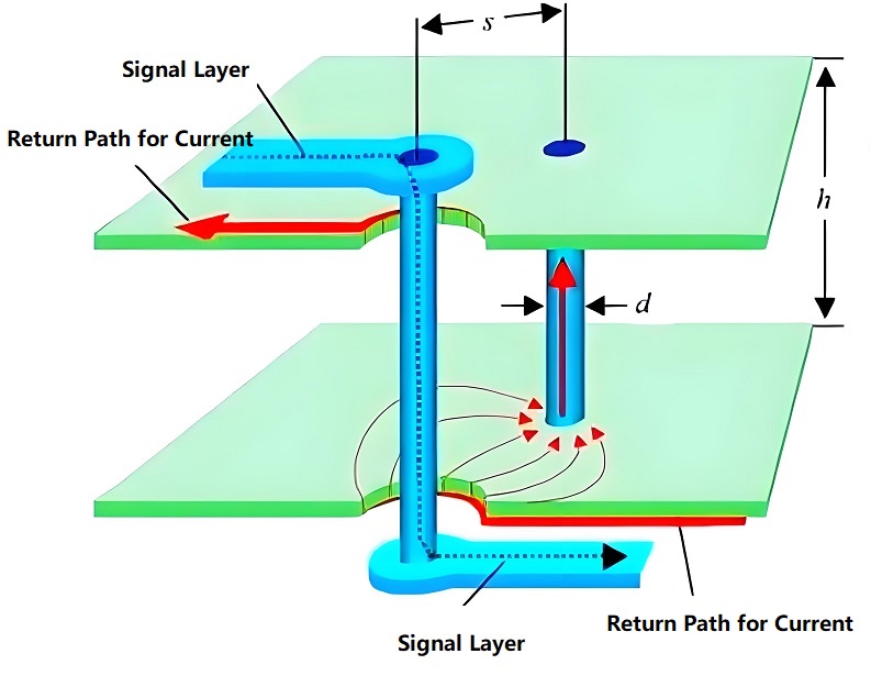
Without a stable GND, circuits can behave unpredictably. Voltage levels may fluctuate, and signals may become distorted. In digital electronics, this can cause logic errors. In analog electronics, it can introduce unwanted noise or distortion.
Ground Symbols in Circuit Diagrams
Understanding GND symbols in circuit diagrams is crucial for designing or troubleshooting circuits. Common symbols include:
- Triangle or a line at the base: Represents a universal or general ground.
- Multiple horizontal lines stacked: Often indicates digital or system ground.
- Three horizontal lines of decreasing width: Represents protective earth (PE) for safety grounding.
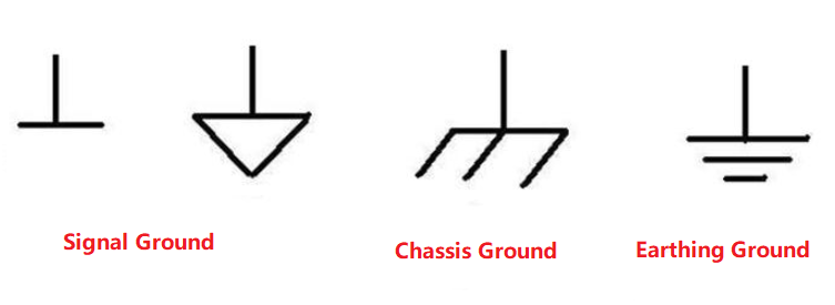
When reading schematics, recognizing these symbols allows engineers to identify different types of ground and design circuits that minimize noise and interference.
Is GND Positive or Negative?
GND is neither strictly positive nor negative. It is the reference point from which all voltages are measured. The potential of any point in the circuit can be positive or negative relative to GND.
For example:
- In a 5V DC circuit, the positive terminal is +5V relative to GND.
- In a split supply system (±12V), points can be +12V or -12V relative to GND.
Generally, GND is treated as 0V, which simplifies measurements and circuit design.
How Does GND Differ in DC and AC Circuits?
DC Circuits:
- GND is usually the negative terminal of the power supply.
- Provides a return path for current.
AC Circuits:
- GND can be connected to the earth or neutral line.
- Provides safety and a reference point for alternating voltage.
While the role of GND is similar, the behavior of AC voltage fluctuates, making grounding crucial for safety. In DC, GND mainly serves as a stable voltage reference.
Difference Between Earthing and Grounding
Many beginners and even some experienced engineers often confuse earthing and grounding. While they are related concepts in electrical and electronic circuits, their purposes are different.
1. Earthing
Earthing, also known as protective earth, is the process of connecting the metallic parts of an electrical device or system to the physical ground (earth). Its main purpose is safety.
Key Points:
- Protects users from electric shock if a live wire accidentally touches the metal body.
- Directs excess current safely into the earth, preventing damage to devices.
- Often mandatory in homes, industries, and hospitals for safety compliance.
For easy to understanding, you can consider it as a metal-cased fan. If a live wire inside the fan comes into contact with the casing, the entire casing becomes live. If the casing is properly earthed, the current flows directly into the ground instead of passing through a person touching the fan.
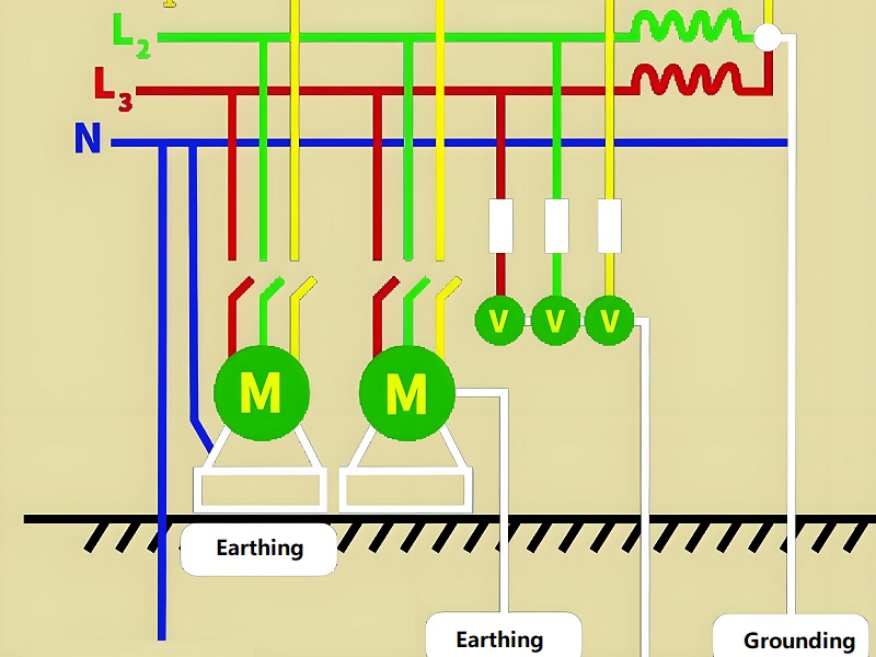
2. Grounding
Grounding, in electronics, is the process of connecting a circuit’s reference point to a common voltage level, typically 0 volts. It is essential for circuit functionality.
Key Points:
- Provides a reference voltage for the entire circuit.
- Ensures stable operation of digital and analog devices.
- Helps current return to the power source, completing the circuit loop.
- Reduces noise and electromagnetic interference (EMI) in sensitive circuits.
In a microcontroller circuit, all voltages are measured relative to the GND pin. The microcontroller reads sensors, powers LEDs, and communicates with other devices using ground as the reference point. Without grounding, voltage levels would fluctuate, and the system might fail.
Here is a detailed comparison table between them, hope this is easy to make you sense:
| Feature | Earthing | Grounding |
| Purpose | Safety; protects users and equipment from electric shock | Circuit reference; ensures proper operation and stability |
| Connection | Connects metal parts or chassis directly to earth | Connects circuit reference point (GND) to a common node or plane |
| Affects Circuit Operation? | No, works only during fault conditions | Yes, essential for accurate voltage measurement and signal integrity |
| Current Flow | Only during fault or leakage current | Normal current returns via GND path |
| Symbol in Schematics | PE symbol (three lines of decreasing length) | Triangle or horizontal line for GND |
| Example | Metal casing of appliances | Microcontroller GND, power supply negative terminal |
In simple terms:
- Earthing is about protecting people and equipment from electric shock.
- Grounding is about providing a stable reference point for circuits.
Do All Circuits Need a Ground?
Do all circuits need a ground? Most circuits require GND for reference and return paths. However, small battery-operated circuits can sometimes function without an external ground.
Still, for complex electronics involving high-speed signals or sensitive analog circuits, proper grounding is essential to maintain signal integrity and safety.
Best Practices for PCB Grounding Design
Effective PCB grounding ensures stable, noise-free circuits. Here are some best practices:
- Single-Point Grounding: Connect different types of ground at a single point to prevent loops.
- Ground Plane: Use a continuous copper layer as a low-impedance return path.
- Separate Analog and Digital Grounds: Isolate sensitive analog circuits from noisy digital circuits.
- Short and Wide Traces: Keep high-frequency signal traces close to the ground plane to minimize impedance.
- Proper Protective Earth Connection: Connect safety ground correctly to protect users without introducing interference.
FAQs
1. Can grounding replace earthing?
No. Grounding provides a voltage reference, while earthing protects against electrical faults. Both serve different purposes.
2. Why do circuits need both earthing and grounding?
Grounding ensures stable operation; earthing ensures safety. Both together provide reliable and safe systems.
3. What happens if earthing is not done?
Without earthing, fault currents may flow through the user, causing electric shock and equipment damage.
4. What is a ground loop?
A ground loop occurs when multiple ground connections create unintended current paths, causing noise or interference.
5. How to implement earthing in PCB design?
Connect metal parts and chassis to a PE pin, separate from GND planes, and ensure a single star point connection if possible.
6. What is the difference between analog and digital ground?
Analog ground reduces noise for analog circuits. Digital ground ensures stable logic signals. Separating them reduces interference.
7. Why do PCBs need a ground plane?
Ground planes provide a low-impedance return path, reducing noise and improving signal stability.
8. What is the difference between earthing and grounding?
Earthing protects users by connecting equipment to earth. Grounding provides a reference for circuit operation.