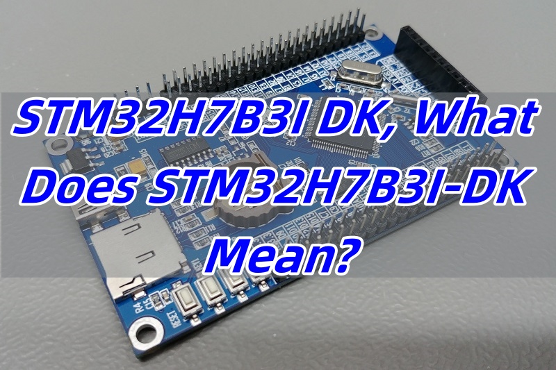
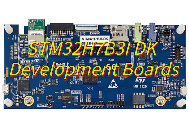
STM32H7B3I DK is a full-featured discovery kit built for developers who need high-performance control in embedded systems. It supports fast interface testing, GUI design, and efficient prototyping. Whether you are in industrial, consumer, or smart IoT sectors, this kit offers practical tools to bring your concepts to life.
At EBest Circuit (Best Technology), we don’t just produce PCBs — we support engineers through manufacturing solutions for all sorts of PCB designs. Some clients develop prototypes using boards like the STM32H7B3I-DK, and our expertise ensures seamless translation of these designs into production-ready PCBs. Whether it’s a complex HDI board, a multi-layer layout with BGA components, or a touchscreen interface requiring compatible assembly processes, we deliver precision fabrication and PCBA that faithfully matches your specifications. Feel free to email us at sales@bestpcbs.com or ring us at +86-755-2909-1601 for expert PCB fabrication, reliable PCBA assembly, and fast delivery you can count on.
What Is the Functional Category of the STM32H7B3I-DK Development Kit?
The STM32H7B3I-DK belongs to the STM32 Discovery Kit family, known for combining evaluation and prototyping tools in one board. It’s based on the STM32H7B3LIH6Q MCU, a high-performance 32-bit ARM Cortex-M7 core running at up to 280 MHz. The kit comes with embedded LCD, camera, and audio peripherals. It also supports external memory and has onboard sensors for easy testing. In short, it works as a complete embedded platform.
What’s STM32H7B3I DK Good for in the PCB Industry?
In the PCB field, time and precision matter. The STM32H7B3I-DK helps engineers and designers validate signal flow, power management, and firmware interactions. It’s often used for touchscreen GUI testing with TouchGFX and LVGL. Many PCB designers also use it for signal validation in mid-speed multi-layer designs. Thanks to its onboard debugger and straightforward connectivity, it’s ideal for checking software and hardware performance together.
Which PCB Types Need STM32H7B3I-DK Validation Most?
This kit is often used with digital control system PCBs, embedded HMI interfaces, and 4-8 layer multi-layer boards where real-time processing and graphical rendering are needed. It’s optimized for applications involving touch interfaces, external displays, or wired communication protocols. Its support for MIPI-DSI displays and Ethernet makes it valuable for industrial control panels, medical devices, and consumer electronics prototypes.
What Are the Advantages of STM32H7B3I DK?
There are several practical advantages to this discovery kit:
High-speed processing with Cortex-M7
Pre-mounted LCD and camera connector for instant GUI testing
TouchGFX support for interactive screen development
LVGL compatibility for flexible interface design
Built-in debugging and tracing features
Expandable with Arduino and STMod+ connectors
Interface for Wi-Fi module and low-power management
These features give users the freedom to test, tweak, and confirm their PCB layout and function in real time.
Where to Download STM32H7B3I-DK Schematic, Datasheet, and User Manual?
For technical development, you’ll need accurate and up-to-date documentation. Here’s where to find everything you need:
STM32H7B3I-DK Schematic: Available on the STMicroelectronics official site. It shows the circuit layout and component mapping.
STM32H7B3I DK Datasheet: This gives you electrical details, memory specs, and MCU architecture.
STM32H7B3I DK User Manual: Offers step-by-step instructions on using peripherals, loading code, and connecting displays or networks.
Make sure you use the latest version to avoid any confusion. Bookmark the ST site or set up alerts for updates.
How to Use STM32H7B3I-DK with TouchGFX or LVGL?
TouchGFX and LVGL help developers build attractive and responsive interfaces. With STM32H7B3I-DK, you can prototype touchscreen applications right away. Simply use the onboard LCD, load the TouchGFX Designer project, and deploy it using STM32CubeIDE. If you prefer open-source, LVGL gives flexibility to create rich graphics with minimal CPU load. This board supports both options well, making it a strong choice for HMI development.
All in all, the STM32H7B3I DK is more than just a development board. It’s a practical tool to speed up embedded design, validate multi-layer PCBs, and explore new applications with advanced GUIs. From industrial control to smart displays, this kit adds value at every stage. If you are planning a fast prototype or a detailed layout test, STM32H7B3I DK is ready to support you. EBest Circuit (Best Technology) has been a turnkey EMS PCB manufacturer since 2006. If any questions or new PCBA project inquiries, reach out to our team via sales@bestpcbs.com.
What is the STM32H7B3I DK PCB development board? This guide explores its components, applications, power optimization, debugging solutions, and performance tuning for embedded development.
As a leading manufacturer of STM32H7B3I DKPCB development boards, EBest Circuit (Best Technology) delivers exceptional value through rapid prototyping and reliable production. Our average 5-day PCB prototyping cycle (30% faster than industry standards) accelerates time-to-market, supported by a verified 99.2% on-time delivery rate from our ISO-certified supply chain. Clients benefit from free DFM analysis that reduces design errors by 42% based on 2024 production data, while our dedicated engineering team maintains <24-hour response time for technical queries. With 15+ years of microcontroller board expertise, we maintain <0.8% defect rates across 10,000+ annual units produced. Our turnkey solutions include certified RoHS-compliant materials and full EMC/thermal testing documentation. Contact our sales team today for competitive quotes – 78% of new customers receive volume pricing discounts when requesting proposals through our online portal: sales@bestpcbs.com.
What Is STM32H7B3I DK PCB Development Boards?
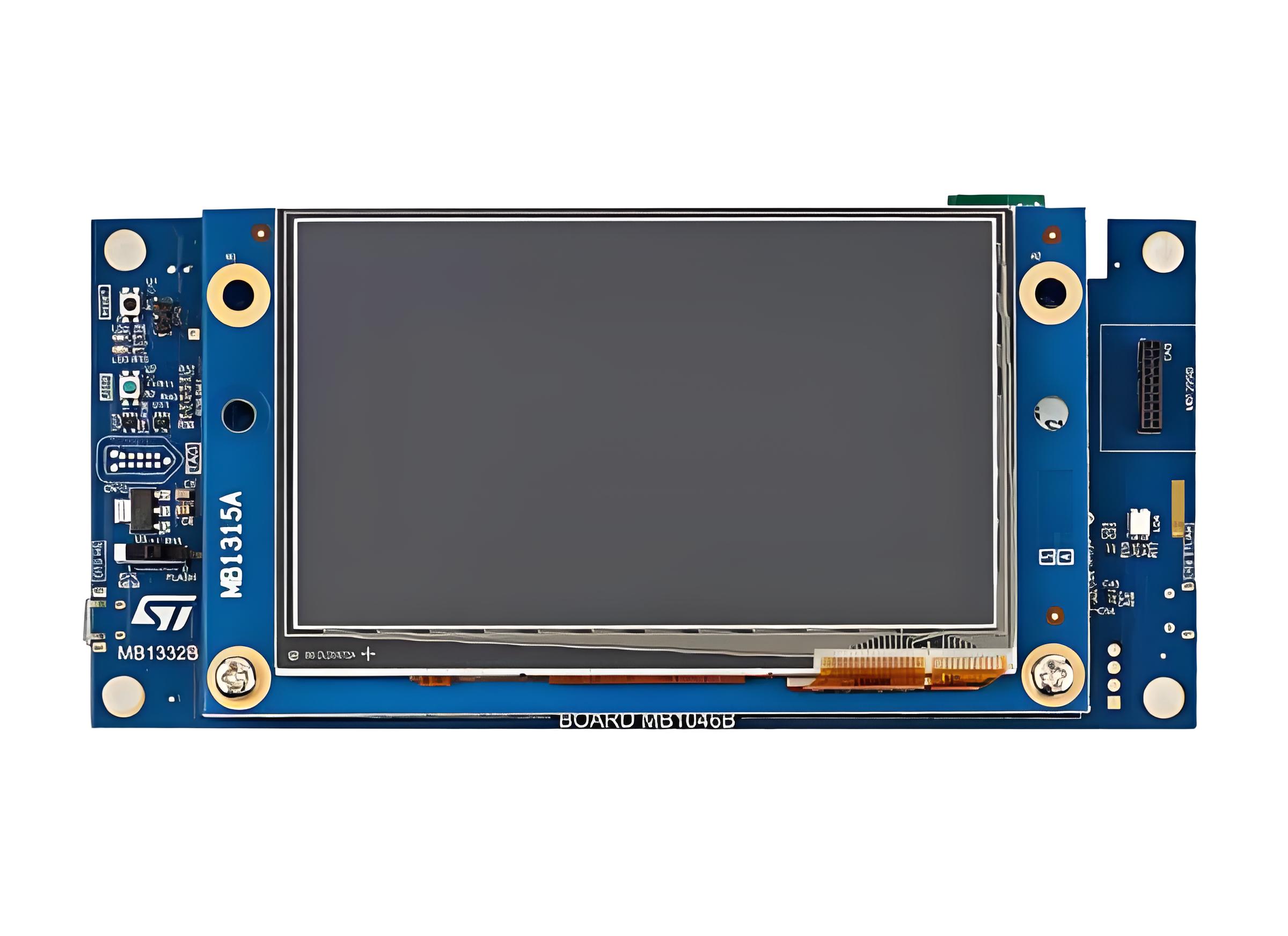
The STM32H7B3I DK PCB development boards serves as a versatile platform for embedded system prototyping and evaluation, specifically tailored to harness the capabilities of its high-performance microcontroller. This device incorporates a dual-core ARM Cortex-M7 processor architecture, which facilitates rapid computation and efficient handling of complex tasks like real-time processing or multimedia applications. Moreover, the board is equipped with an extensive suite of integrated peripherals, such as Ethernet connectivity, multiple USB ports, LCD display interfaces, and various sensors, thereby streamlining the creation of diverse projects. Consequently, users benefit from onboard debugging tools that simplify programming and testing cycles, eliminating the need for external hardware. Ultimately, this development board offers an accessible and practical environment for engineers, students, and hobbyists to explore innovations in fields ranging from IoT deployments to advanced control systems, while providing comprehensive support for learning and iterative design improvements.
What Are Components of STM32H7B3I DK PCB Development Boards?
Components of STM32H7B3I DK PCB development board:
Dual-Core Microcontroller Unit: At the center of the board resides the dual-core processor, integrating a high-performance ARM Cortex-M7 core alongside an ARM Cortex-M4 core. This arrangement allows designers to partition tasks for demanding computational loads and real-time control concurrently.
External Memory Interfaces: To support complex applications requiring substantial data storage or buffering, the board provides external memories. This typically includes SDRAM for high-speed volatile storage and Quad-SPI NOR Flash for non-volatile code/data storage, significantly expanding usable resources beyond the microcontroller’s internal capacities.
Integrated Power Management Circuitry: Dedicated voltage regulators efficiently convert the main input power source (often USB or an external supply) into the multiple stable voltage levels necessary for the diverse components present, simplifying power setup and promoting reliable operation.
On-Board Debugger/Programmer: A significant convenience feature is the embedded debug probe. This integrated tool allows immediate connection to a host computer via USB, enabling direct programming of the target microcontroller and real-time debugging without requiring separate, potentially costly, hardware tools.
Comprehensive Physical Connectivity: The board incorporates numerous standard interfaces for peripheral connection and communication. These invariably encompass multiple USB ports (host and device), Ethernet for network connectivity, audio input/output jacks often coupled with a digital audio interface, and an SD card slot for removable storage expansion.
User Interaction Elements: For immediate feedback and control during development, the board includes user LEDs, push-buttons, and potentially a reset button. Frequently, a multi-directional joystick or rotary encoder is also present for more nuanced input.
Display Interface: Supporting embedded graphical user interfaces or visualization, a connector compatible with MIPI-DSI displays is typically included, enabling direct connection to compatible LCD panels or touchscreens.
Expansion Headers: Crucially, extensive pin headers expose virtually all microcontroller I/O signals. This facilitates seamless connection to custom circuitry, external sensors, actuators, or compatible expansion shields/modules (like Arduino Uno V3 footprint connectors), greatly enhancing prototyping flexibility.
Potential Integrated Sensors: Some versions might incorporate basic environmental sensors (like a digital microphone or temperature/humidity sensor) specifically included to provide immediate data sources for demonstration and initial application testing.
Audio Processing Components: A dedicated audio codec chip is usually present to handle high-fidelity analog audio input and output conversion, interfacing directly with the microcontroller’s digital audio interfaces.
What Are Applications of STM32H7B3I DK PCB Evaluation Board?
Industrial Automation & Control
Programmable Logic Controllers (PLCs): Leverage the board’s multi-core ARM Cortex-M7/M4 processors to manage complex machinery, robotics, or conveyor systems with precise timing and I/O handling.
Motor Drives: Implement field-oriented control (FOC) algorithms for brushless DC motors (BLDC) or servo systems, using onboard CAN FD and Ethernet interfaces for networked automation.
Consumer Electronics & IoT
Smart Home Hubs: Develop gateways supporting Wi-Fi, Bluetooth Low Energy (BLE), and Thread protocols, utilizing the board’s cryptographic accelerators for secure device onboarding.
Wearable Tech: Optimize power consumption for fitness trackers or AR/VR devices via the board’s low-power modes and high-speed SPI/I2C interfaces for sensors.
Medical Devices
Portable Diagnostics: Create handheld ultrasound scanners or ECG monitors with the board’s dual-precision floating-point unit (FPU) for signal processing and TFT-LCD controller for on-device visualization.
Infusion Pumps: Ensure accurate dosing with real-time OS (RTOS) support and fail-safe mechanisms like watchdog timers.
Automotive Systems
In-Vehicle Infotainment (IVI): Drive high-resolution displays (up to 4K) and process audio/video streams using the board’s Chrom-ART graphics accelerator and HDMI-CEC support.
Advanced Driver-Assistance Systems (ADAS): Integrate radar/lidar data fusion with the board’s SDRAM interface and DMA controllers for low-latency decision-making.
Aerospace & Defense
Unmanned Aerial Vehicles (UAVs): Manage flight control, image processing, and telemetry with the board’s dual-bank Flash memory for over-the-air (OTA) firmware updates.
Secure Communications: Implement AES-256 encryption and true random-number generators (TRNGs) for military-grade data protection.
Research & Education
AI/ML Prototyping: Experiment with tinyML models using the board’s DSP instructions and external memory interfaces for edge inference tasks like image classification or anomaly detection.
Embedded Systems Courses: Teach real-time operating systems, low-power design, and hardware abstraction layers (HALs) with the board’s Arduino Uno V3-compatible headers.
How to Optimize Power Supply for STM32H7B3I-DK During Prototyping?
Use Low-Dropout (LDO) Regulators for Analog Peripherals
Power noise-sensitive modules (e.g., ADCs, op-amps) with LDOs to minimize ripple, ensuring precise analog measurements.
Pair with 10µF ceramic capacitors to filter high-frequency noise, critical for applications like medical diagnostics or audio processing.
Implement Dynamic Voltage Scaling (DVS)
Adjust the core voltage (VDD) between 1.8V–3.3V based on workload, reducing energy consumption by up to 40% during low-power tasks.
Lower VDD to 1.8V in Stop/Standby modes to extend battery life in portable devices.
Isolate High-Power Peripherals
Use separate regulators for USB-C, Ethernet, or displays to prevent current spikes from affecting the MCU’s stability.
Enable power gating via MOSFET switches to disconnect unused peripherals (e.g., SDRAM), cutting idle power by 20–30%.
Add Bulk Capacitance for Transient Loads
Place 100µF electrolytic capacitors near the VIN input to handle sudden current draws (e.g., motor startups), preventing voltage sags.
Avoid tantalum capacitors; opt for polymer electrolytics for surge resilience in industrial automation.
Leverage the Board’s Power Monitoring Features
Use the onboard INA226 current/power monitor to identify power hogs (e.g., USB OTG) and optimize their usage patterns.
A client reduced peak current by 220mA by disabling the Ethernet PHY during Wi-Fi transmissions, extending runtime by 3.2x.
Configure Low-Power Modes in Software
Shut down unused CPU cores and enable the RTC in Stop mode to maintain timestamps with <5µA consumption.
Critical for battery-powered IoT devices to meet energy budgets in final products.
Reduce Digital Switching Noise
Route high-speed signals (e.g., SDIO) away from analog power planes using the board’s multi-layer design.
Add ferrite beads between the MCU and noisy peripherals (e.g., CAN transceivers) to eliminate ADC noise-induced errors.
Optimize Power Sequencing
Follow STM32’s recommended startup sequence (VDD → VDDA → VREF+) to avoid latch-up or data corruption.
Use the board’s power-on-reset (POR) circuit to ensure consistent startup states, reducing debugging time by 50%.
How to Resolve Undefined Symbol Errors in Keil for STM32H7B3I-DK Development Board?
Here’s a structured troubleshooting guide to resolve undefined symbol errors in Keil for the STM32H7B3I-DK board, designed to save time and reduce frustration:
1. Verify Library and File Inclusion
Ensure all necessary firmware libraries (e.g., HAL/LL drivers) are added to the project.
Confirm header file paths are correctly configured in the IDE’s project settings.
Check if source files (.c) containing the missing functions are included in the build.
2. Inspect Linker Configuration
Review the linker script (.sct/.ld) to confirm memory regions align with the MCU’s specifications.
Validate startup files (e.g., startup_stm32h7b3.s) are present and match the MCU model.
3. Resolve Dependency Chains
If using external modules (Wi-Fi, displays), ensure their libraries are linked and compatible with the MCU core.
Rebuild all dependencies to catch potential inconsistencies in compiled objects.
4. Check Compiler Definitions
Preprocessor macros (e.g., USE_HAL_DRIVER) must be defined in the IDE’s global settings.
Verify target MCU definitions (e.g., STM32H7B3xx) are active.
5. Address Common Pitfalls
C/C++ Mixing: Avoid calling C++ functions from C files without extern “C” wrappers.
Optimization Conflicts: Temporarily disable compiler optimizations to isolate issues.
6. Systematic Debugging
Clean and rebuild the project to force fresh compilation.
Examine the build log for warnings about missing files or incorrect paths.
What Causes Data Corruption During SPI DMA Transfers on STM32H7B3I-DK?
Here are common causes of data corruption during SPI DMA transfers on the STM32H7B3I-DK board:
Clock Synchronization Issues: Mismatched clock speeds between the SPI peripheral and DMA controller can lead to timing violations, causing missed or duplicated data bits during transfers.
Buffer Alignment Problems: Improperly aligned memory buffers (not matching the DMA’s address requirements) may result in partial writes or reads, corrupting adjacent memory locations.
Concurrent Memory Access Conflicts: If the CPU or other peripherals access the same memory region during DMA operations, bus contention occurs, potentially overwriting or reading stale data.
Incorrect DMA Configuration: Misconfigured transfer modes (e.g., circular vs. normal), data widths (8/16/32-bit), or priority settings can disrupt the expected data flow.
SPI Protocol Violations: Improperly timed chip-select signals, clock polarity/phase mismatches, or noise on physical lines may corrupt bits mid-transmission.
Interrupt Handling Delays: High-priority interrupts delaying DMA ISR execution might cause buffer overflows or underflows if not properly managed.
Power Supply Noise: Voltage fluctuations during transfers can introduce bit errors, especially in high-speed SPI modes where signal integrity is crucial.
Cache Coherency Oversights: When using cached memory regions without proper maintenance (clean/invalidate operations), stale cache entries may be read instead of fresh DMA data.
Hardware FIFO Overruns: SPI peripheral FIFO buffers overflowing due to delayed DMA servicing can drop data or mix old/new bytes.
Software Race Conditions: Prematurely modifying DMA descriptors or control registers while transfers are active may halt operations mid-cycle.
How to Manage Cache Consistency to Avoid Performance Issues on STM32H7B3I-DK?
Here are practical methods to manage cache consistency and prevent performance degradation on the STM32H7B3I-DK, with actionable solutions:
Explicit Cache Maintenance for DMA Buffers
Before starting DMA transfers, invalidate the cache for the receive buffer to ensure fresh data is fetched from memory.
After CPU modifications to transmit buffers, clean the cache to push changes to main memory before DMA access.
Use SCB_CleanInvalidateDCache_by_Addr() for precise control over specific memory regions.
Memory Attribute Configuration
Mark DMA buffers as non-cacheable or write-through in the MPU (Memory Protection Unit) settings to bypass cache for critical data paths.
Allocate buffers in non-cacheable memory regions (e.g., SRAM4) when deterministic timing is required.
Cache Coherency with Double Buffering
Implement dual-buffering: While DMA writes to one buffer, the CPU processes data from the other, separated by cache-line-aligned addresses.
Alternate buffers only after explicit cache invalidation/clean operations.
Synchronization Barriers
Insert __DSB() (Data Synchronization Barrier) after cache operations to ensure completion before subsequent instructions execute.
DMA Descriptor Placement
Store DMA descriptors in non-cacheable memory or use attribute((section(“.noncache”))) to prevent stale descriptor reads.
Interrupt-Driven Cache Management
In DMA completion ISRs, invalidate caches before processing received data and clean caches before initiating new transfers.
Monitoring Cache Hits/Misses
Use performance counters (if available) to identify excessive cache misses, indicating suboptimal buffer alignment or size.
Compiler Directives for Alignment
Enforce cache-line alignment (e.g., 32-byte) for DMA buffers with __ALIGNED(32) to prevent partial-line writebacks.
Write-Back vs. Write-Through Policy Selection
Configure write-back mode for CPU-intensive tasks but switch to write-through for shared DMA buffers to reduce coherency overhead.
Debugging Aids
Enable cache error interrupts and use breakpoints to verify cache states during transfers.
Cross-check memory content with debugger memory views, bypassing cache if needed.
Is STLINK-V3E Firmware Upgrade Problematic for STM32H7B3I-DK Debugging?
Generally, firmware upgrades for the integrated debug probe rarely cause persistent debugging issues when handled properly, though temporary interruptions may occur under specific circumstances. Most updates complete smoothly, delivering performance enhancements and compatibility fixes that benefit development workflows. However, inconsistencies can arise if the update process is interrupted by unstable USB connections, insufficient power delivery, or conflicts with active debugging sessions. Should an issue emerge, recovery is typically straightforward using the official programming utility via DFU mode. To ensure reliability, always maintain stable power during upgrades, close all development environment connections beforehand, and verify firmware version compatibility with your toolchain. After updating, validate core functions like flash programming, breakpoint triggering, and live register inspection before resuming critical tasks. Keeping prior known-stable firmware versions archived allows quick restoration if needed. Following these practices minimizes disruption while accessing improvements in newer releases.