pcb
Home > Blog

Posts Tagged ‘SSD PCB’

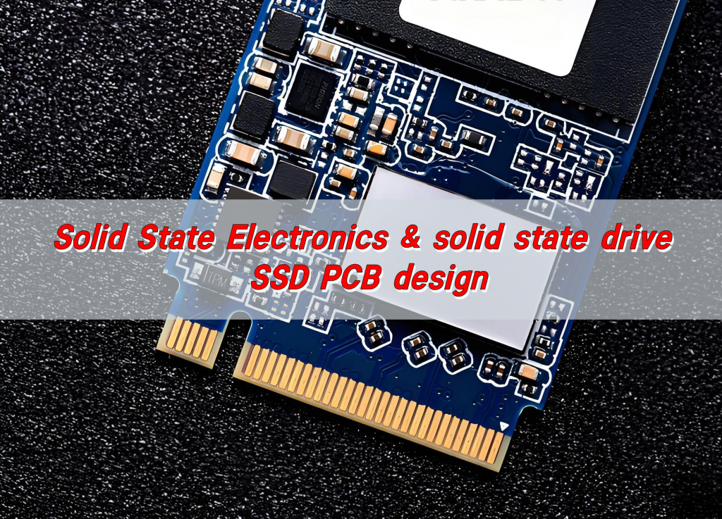
Solid State Electronics & solid state drive SSD PCB design
Tuesday, February 25th, 2025

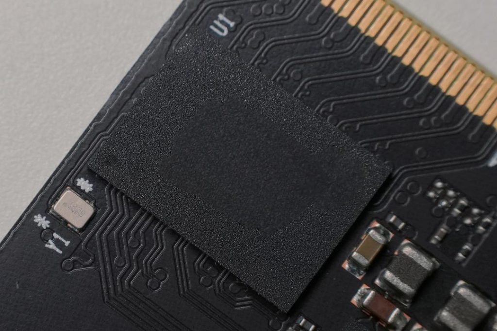
Solid state drive SSD PCB design requires reasonable layout of controllers, flash memory chips, power management modules and interfaces (such as SATA or NVMe), optimization of power supply and ground plane to reduce noise, and consideration of heat dissipation solutions to ensure efficient data transmission and stable operation.

Solid State Electronics & solid state drive SSD PCB design

At Best Technology, we specialize in high-quality SSD PCB design and manufacturing, offering expert solutions for both consumer and enterprise-grade SSDs. With cutting-edge technology, advanced thermal management, and top-grade materials, we ensure your SSD PCBs deliver optimal performance and reliability.

What is SSD PCB?

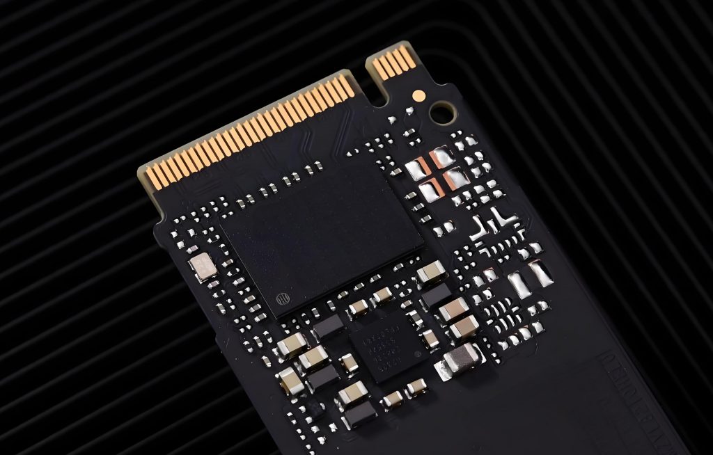
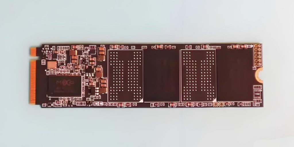
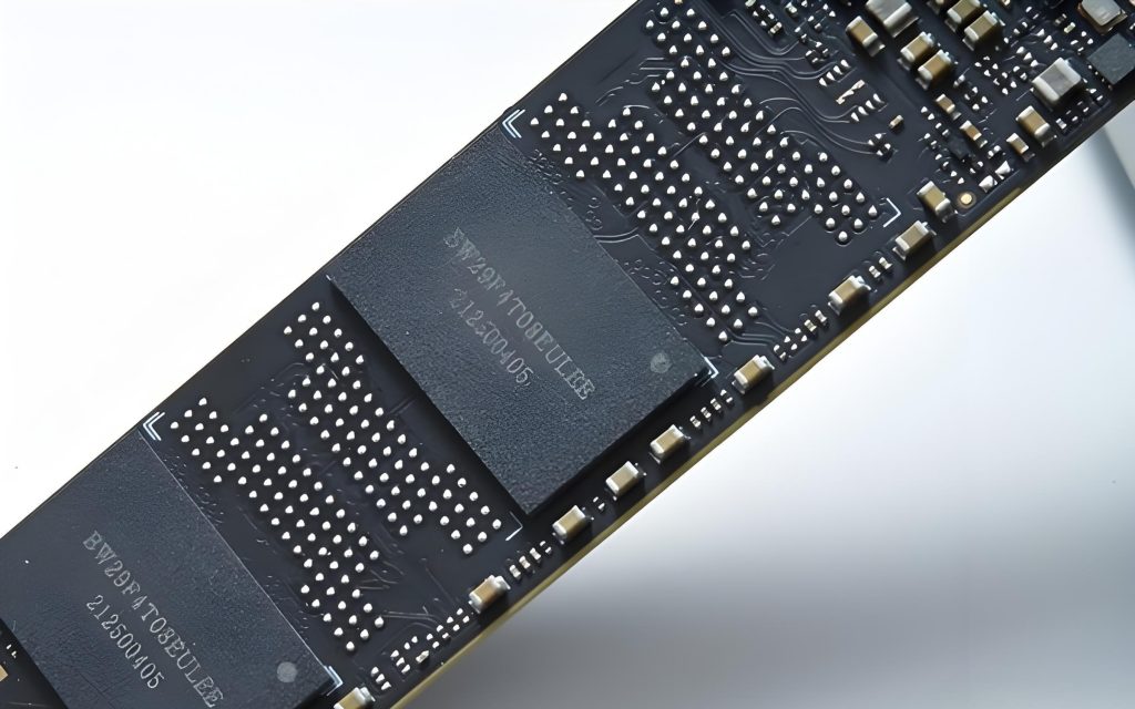
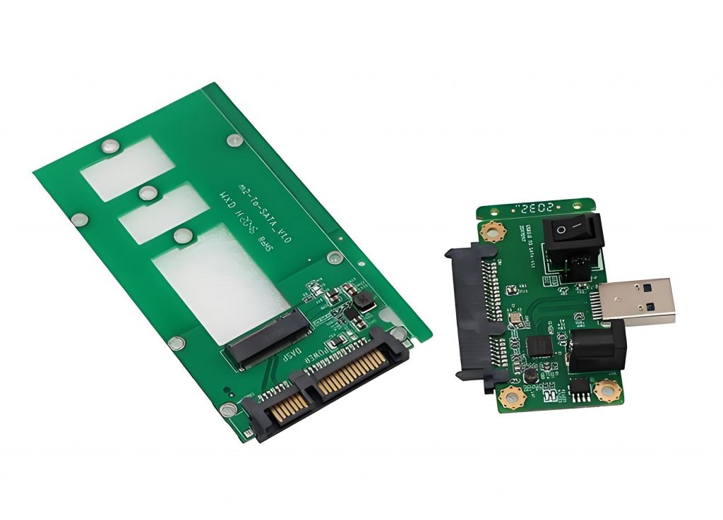
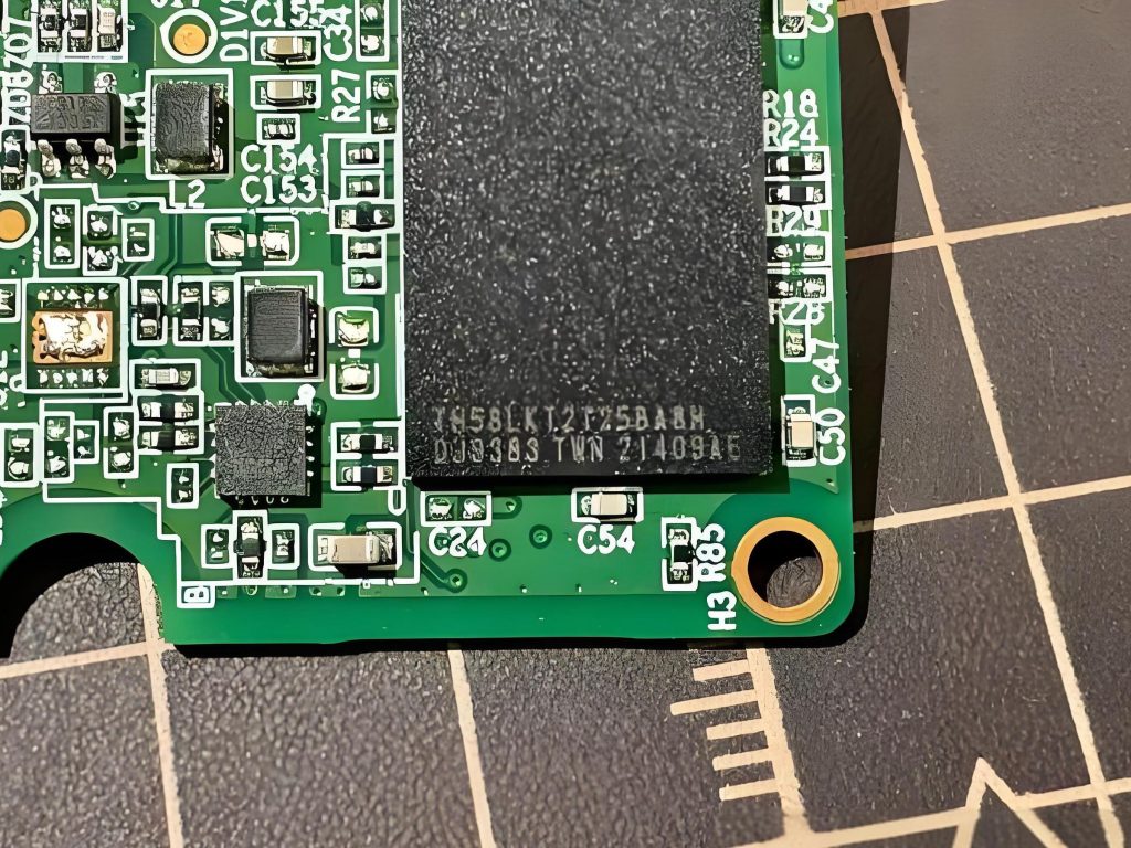
An SSD PCB, or Solid-State Drive Printed Circuit Board, is the backbone of a solid-state drive. It’s the platform that holds the essential components like the flash memory chips, controller, and interface connectors. The PCB provides the electrical pathways that connect these components and ensures smooth communication between them.

At its core, the SSD PCB is what enables the SSD to function as a fast, reliable storage device. Without the proper design and materials, even the best flash memory chips and controllers would not perform optimally.

A well-designed SSD PCB ensures minimal power loss, maximum efficiency, and stable data transfer speeds.

What is SSD PCB design?

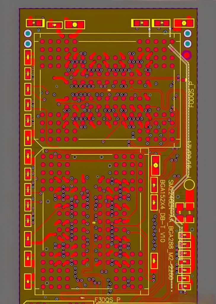
SSD PCB design involves creating a blueprint for the SSD’s printed circuit board. This includes selecting the right materials, ensuring optimal routing for electrical signals, managing heat dissipation, and considering layout factors that will allow the SSD to perform at its best.

A good SSD PCB design takes into account factors such as:

  • Electrical Pathways: The routing of signals between memory chips, controllers, and other components is critical. Poor routing can lead to signal interference, which can reduce performance.
  • Thermal Management: Poor heat dissipation can lead to overheating, affecting the longevity and reliability of the drive.
Solid State Electronics & solid state drive SSD PCB design
  • Component Placement: The arrangement of the components on the PCB impacts the drive’s performance and overall reliability. The design must minimize interference and ensure efficient data flow.

How does PCB design affect SSD speed?

PCB design plays a significant role in determining the speed of an SSD. In fact, the efficiency of the PCB’s layout can make a difference between an average SSD and one that performs at peak speeds.

Proper routing minimizes signal degradation, which is essential for maintaining high-speed data transfer. If the signals are routed inefficiently, delays can occur, slowing down the drive.

Additionally, the use of high-quality PCB materials with low resistance and impedance ensures faster data transfer. The components on the PCB must be placed to avoid interference, and careful design is necessary to keep data access times short and boost read/write speeds.

PCB design: SSD longevity factor?

The longevity of an SSD is another aspect that can be influenced by PCB design. SSDs have a finite number of write/erase cycles due to the nature of flash memory, but good PCB design can help maximize the number of cycles by optimizing power management and ensuring thermal efficiency.

If thermal management is not prioritized in the design, the drive could experience premature failure. Proper heat dissipation allows the components to operate at their optimal temperature, reducing stress on the memory chips and improving the overall lifespan of the drive.

Moreover, optimizing the power delivery system on the PCB helps reduce the wear on the memory chips. Smooth and efficient power distribution ensures that the SSD runs at a steady voltage level, preventing damage to sensitive components.

Why is thermal management critical for SSD PCBs?

SSDs can generate significant heat during operation, especially when performing heavy write operations. If this heat isn’t properly managed, it can cause thermal throttling, where the SSD slows down to prevent damage. In the worst case, excessive heat could lead to component failure and data loss.

To avoid these issues, SSD PCBs are designed with heat sinks, thermal pads, and efficient routing that allow heat to dissipate quickly.

Solid State Electronics & solid state drive SSD PCB design

Additionally, using materials with good thermal conductivity ensures that the heat generated by the SSD components is spread out evenly, preventing hot spots.

In high-performance SSDs, effective thermal management can make the difference between optimal performance and premature failure. Therefore, choosing the right PCB materials and layout is essential for maintaining the temperature within acceptable limits.

What is the biggest drawback to SSD drives?

Despite their many advantages, SSDs do have one significant drawback: their limited write endurance. Flash memory in SSDs has a limited number of program/erase cycles. As data is written to and erased from the drive, the memory cells experience wear, which eventually leads to failure.

However, good PCB design can help mitigate this issue by distributing writes evenly across the memory cells. This is done through wear leveling algorithms in the SSD controller. These algorithms ensure that the cells don’t wear out prematurely by spreading data writes across the available memory.

Which lasts longer, HDD or SSD?

In terms of durability and longevity, HDDs (hard disk drives) generally last longer than SSDs in terms of read/write cycles.

However, SSDs offer better performance and reliability in most real-world use cases. While HDDs can be prone to mechanical failures due to moving parts, SSDs, being solid-state, are more resistant to physical shock and damage.

When comparing lifespan, an SSD can endure a few years of heavy usage before the flash memory starts to degrade, while an HDD might last longer under light usage.

What are the best materials for SSD PCBs?

The materials used for SSD PCBs are critical in ensuring both performance and durability. High-quality materials such as FR4, polyimide, and ceramic are commonly used in the production of SSD PCBs.

  • FR4: The most commonly used PCB material, FR4 is a fiberglass-based epoxy laminate. It’s affordable and has good electrical insulating properties, making it a standard choice for SSD PCBs.
Solid State Electronics & solid state drive SSD PCB design
  • Polyimide: Used in flexible and rigid-flexible PCBs, polyimide is a high-performance material with excellent thermal stability and mechanical properties.
  • Ceramic: Known for its high thermal conductivity, ceramic is used in some high-end SSD designs to ensure efficient heat dissipation.

In addition to these materials, the selection of high-quality soldering materials and conductive adhesives is essential for ensuring a reliable connection between components.

How do multi-layer PCBs benefit SSDs?

Multi-layer PCBs are often used in SSD designs to enhance both performance and density. These PCBs consist of multiple layers of conductive material, allowing for more complex circuit routing without taking up extra space.

Multi-layer PCBs also contribute to thermal management by distributing heat across several layers, reducing the risk of overheating.

Conclusion:

In conclusion, the design of the SSD PCB plays an essential role in determining the drive’s speed, reliability, and longevity. A well-designed SSD PCB ensures optimal performance, efficient thermal management, and long-lasting durability.

For reliable and high-performance SSD PCB design, look no further than Best Technology. Our team specializes in designing and manufacturing advanced PCBs tailored to meet the needs of the modern electronic industry. Contact us at sales@bestpcbs.com

You may also like

SSD PCBA & What is SSD PCB?
Friday, February 21st, 2025

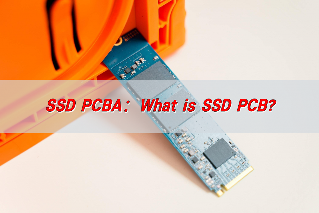
SSD PCBA refers to the process of soldering electronic components to the PCB of a solid-state drive through SMT or DIP processes to form a circuit board assembly with specific functions. It includes components such as controllers, flash memory chips, capacitors, resistors, etc., which are used to realize functions such as data storage, read and write operations, and transmission.

SSD PCBA & What is SSD PCB?

What is SSD PCB?

An SSD PCB is the circuit board where all the critical components of an SSD are mounted. It is designed to provide electrical connections between NAND flash memory chips, the SSD controller, voltage regulators, and capacitors.

The quality and design of the PCB impact the SSD’s speed, power consumption, and lifespan. High-quality materials and precise manufacturing processes are crucial in ensuring the reliability and durability of an SSD.

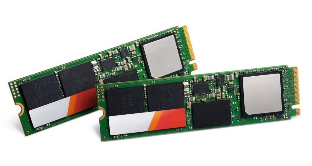
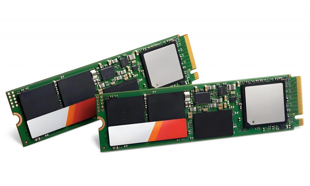
Different types of SSDs have varying PCB designs, optimized for form factors such as M.2, SATA, and PCIe NVMe SSDs. Each form factor has a specific PCB layout to accommodate the required components while maintaining efficiency. For instance, M.2 SSDs use compact PCBs that allow them to fit into ultra-thin laptops and high-performance desktops.

What is SSD in semiconductor?

An SSD is fundamentally a semiconductor-based storage device that uses NAND flash memory instead of spinning disks. In semiconductor technology, SSDs consist of multiple layers of NAND memory cells fabricated on silicon wafers.

These memory cells store data electronically and retain it even when power is turned off. The semiconductor industry has continuously innovated SSD technology, introducing 3D NAND to increase storage density and reliability.

Unlike mechanical hard drives, SSDs have no moving parts, making them more resistant to shock and vibration. The advancement of semiconductor technology has enabled higher-capacity SSDs with faster read/write speeds, reduced power consumption, and longer lifespans.

What does SSD mean in manufacturing?

In manufacturing, SSD production involves PCB assembly (PCBA), NAND memory integration, controller programming, and rigorous testing.

SSD manufacturing begins with designing and fabricating the PCB, ensuring it meets industry standards for high-speed data processing.

SSD PCBA & What is SSD PCB?

During PCB assembly (PCBA), components such as the SSD controller, DRAM cache, and NAND flash chips are mounted onto the board using Surface Mount Technology (SMT).

Advanced SMT processes ensure precise placement, strong solder joints, and minimal defects. After assembly, firmware is loaded onto the SSD controller, enabling it to manage data transfer and error correction.

The final stage includes extensive testing and quality control, where SSDs undergo thermal, electrical, and performance tests to ensure they meet durability and speed requirements.

How to assemble SSD PCB?

Assembling an SSD PCB requires multiple steps, integrating semiconductor chips, power management circuits, and high-speed interfaces onto a compact board.

  • PCB Fabrication: The process begins with manufacturing a high-quality PCB, typically made from multilayer FR4 or high-frequency materials.
  • Component Placement: Using automated SMT machines, components such as NAND flash memory, SSD controllers, and capacitors are precisely placed onto the board.
  • Soldering and Reflow Process: After placement, the board undergoes a reflow soldering process, where it is heated to secure the components.
  • Firmware Installation: Once assembled, the SSD controller is programmed with firmware to optimize data processing, wear leveling, and error correction.
  • Testing and Quality Assurance: Each SSD undergoes performance testing, including stress tests, endurance tests, and data integrity checks to ensure reliability.

What are the three types of SSDs?

SSDs are categorized based on form factors and interfaces, determining their speed, compatibility, and application.

  • SATA SSDs: These SSDs use the Serial ATA (SATA) interface, offering speeds up to 600MB/s. They are commonly found in older laptops and desktops.
  • NVMe SSDs: Utilizing the PCIe (Peripheral Component Interconnect Express) interface, NVMe SSDs provide significantly faster speeds, reaching up to 7,000MB/s in high-end models.
  • M.2 SSDs: Designed for compact spaces, M.2 SSDs come in both SATA and NVMe variants, making them ideal for ultrabooks, gaming PCs, and high-performance systems.

Each type has distinct advantages, with NVMe SSDs being the fastest and most efficient, while SATA SSDs remain a cost-effective choice for general storage.

SSD PCB vs HDD PCB, what are their differences?

There are many differences between SSD PCB (solid state drive printed circuit board) and HDD PCB (mechanical hard disk printed circuit board), as follows:

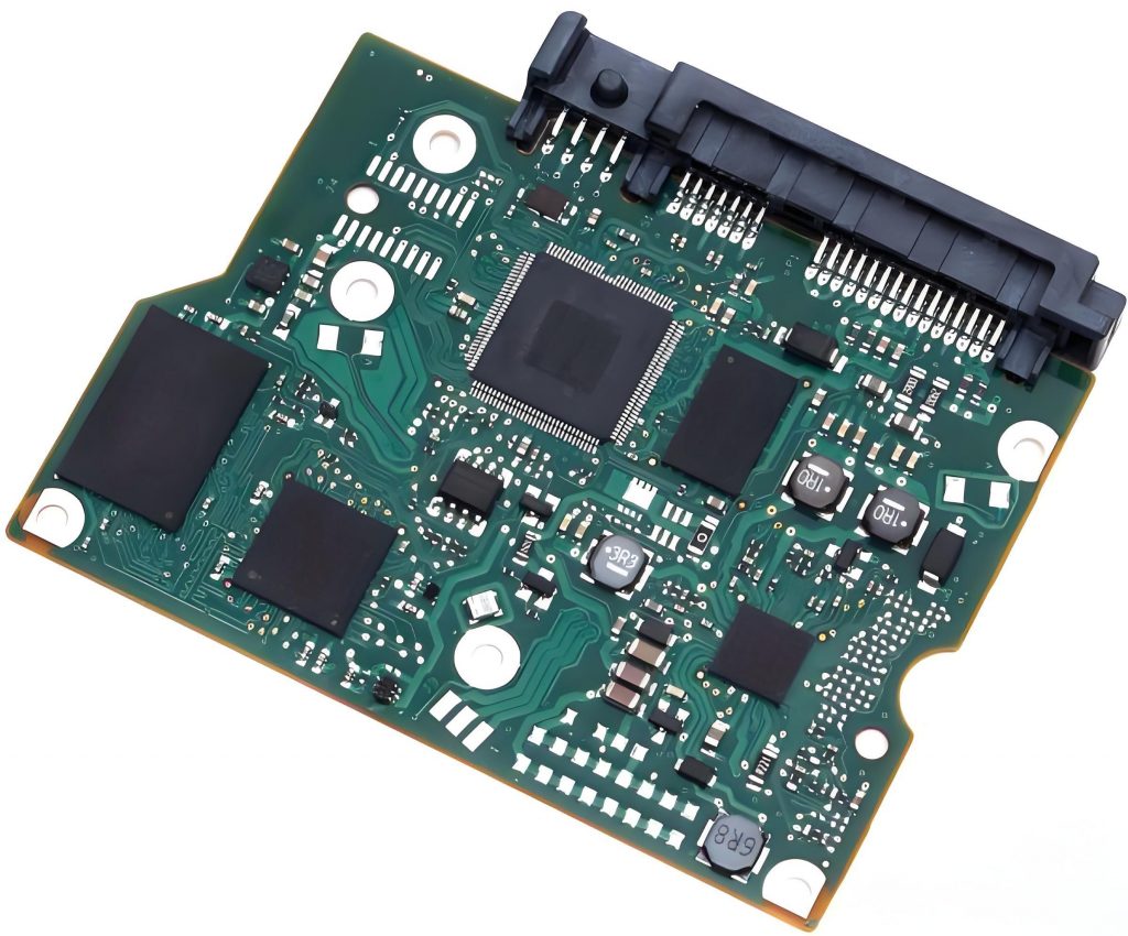
The main control chip on the SSD PCB is responsible for managing and transmitting data, the flash memory chip is used to store data, and some have cache chips for accelerated reading and writing. The main control chip on the HDD PCB is responsible for data transmission and instruction processing, the motor drive chip controls the rotation of the disk and the movement of the head, and the cache chip temporarily stores data.

SSD PCBA & What is SSD PCB?

Common interfaces of SSD include SATA, M.2, PCI-E, U.2, etc. HDD generally uses SATA or SAS interface.

In order to achieve high-speed data transmission, the wiring requirements of SSD PCB are strict, and precise impedance control and signal integrity design are required. Multilayer boards are often used. HDD PCB wiring is relatively simple, and the focus is on connecting components such as heads, motors and main control chips to ensure data transmission and the operation of mechanical components.

SSD does not have high-power components such as motors, and the overall power consumption is low. The power management circuit only needs to provide a stable voltage for the chip. HDD needs to provide a large drive current for the motor to ensure disk rotation and head seek, and the power management circuit is more complex.

SSDs come in a variety of sizes, including 2.5-inch and M.2. HDDs are usually 3.5-inch or 2.5-inch.

SSDs have no mechanical parts and are highly shock-resistant, but flash memory chips have wear and power-off data loss problems, and wear leveling and other technologies are needed to improve reliability. HDD mechanical parts are susceptible to vibration and collision, causing the head to scratch the disk or motor failure, and protection circuits such as vibration sensors are often designed on the PCB.

What is a PCB in a computer?

A PCB in a computer is the fundamental electronic platform that connects components like the processor, memory, storage, and expansion cards. The most critical PCB in a computer is the motherboard, which serves as the communication hub between all internal hardware.

SSDs have their dedicated PCBs for managing data storage, but other PCBs in a computer include graphics card PCBs, power supply PCBs, and network adapter PCBs. Each PCB is designed to ensure seamless operation and efficient power management.

What are the advantages of SSD PCB?

The use of high-quality SSD PCBs offers numerous benefits:

  • Faster Data Processing: SSD PCBs are optimized for high-speed memory access, allowing for quick boot times and fast application loading.
  • Lower Power Consumption: Compared to HDDs, SSDs consume less energy, making them ideal for laptops and battery-powered devices.
SSD PCBA & What is SSD PCB?
  • Durability and Shock Resistance: With no moving parts, SSDs are resistant to physical shocks, reducing failure rates and improving reliability.
  • Compact Design: SSD PCBs are designed for smaller form factors, enabling them to fit into ultra-thin devices without compromising performance.

What are the disadvantages of SSD?

Despite their advantages, SSDs have some limitations to consider:

  • Higher Cost per GB: SSDs are generally more expensive than HDDs, especially for higher storage capacities.
  • Limited Write Cycles: NAND flash memory has a finite number of write cycles, leading to wear over time.
  • Data Recovery Challenges: Unlike HDDs, data recovery from a failed SSD is more complex, requiring specialized tools and expertise.

Conclusion:

SSD PCBs play a vital role in modern data storage, offering high-speed performance, reliability, and efficiency.

For high-quality SSD PCB manufacturing and assembly, Best Technology offers cutting-edge solutions tailored to your needs. Contact us at sales@bestpcbs.com for expert guidance and customized SSD PCB solutions.
You may also like

What is SSD PCB? SSD Circuit Boards Fabricator
Tuesday, January 14th, 2025

What is SSD PCB? SSD PCB is the core component of solid-state drives, used to connect and realize communication and data transmission between various components. It is usually composed of a multi-layer printed circuit board, integrating key components such as the main control chip, NAND flash chip, cache chip (some hard drives do not have DRAM), etc.

What is SSD PCB? SSD Circuit Boards Fabricator

What is SSD PCB?

An SSD PCB is the printed circuit board that houses the essential components of a solid-state drive. It is designed to support NAND flash memory chips, a controller, and other electronic parts that allow the SSD to store and retrieve data efficiently.

The layout of the PCB directly impacts the drive’s performance, heat dissipation, and durability.

Modern SSD PCBs are engineered to handle high-speed data transfer and optimize energy efficiency. They are compact and lightweight, making them ideal for portable devices.

Additionally, advancements in PCB technology have enabled multi-layer designs, which improve performance and reliability.

What Does SSD Mean in Manufacturing?

In manufacturing, SSD stands for Solid-State Drive. It refers to a storage device that uses solid-state memory to store data, unlike traditional hard drives that rely on spinning disks.

SSD manufacturing involves assembling various components, including the PCB, memory chips, and controllers, into a compact and efficient storage solution.

The manufacturing process of SSDs requires precision and expertise. Each component must be carefully integrated to ensure optimal performance.

The PCB acts as the foundation, connecting all elements and ensuring seamless communication between them. Advanced techniques like surface-mount technology (SMT) are often used to create compact and reliable designs.

What is PCB in Hard Drive?

In both SSDs and traditional hard drives, the PCB serves as the foundational platform that connects all components. For SSDs, the PCB integrates NAND flash memory, a controller chip, and power management systems.

What is SSD PCB? SSD Circuit Boards Fabricator

In hard disk drives (HDDs), the PCB also includes circuits that control the motor and read/write heads. SSD PCBs, however, are more advanced and compact due to their solid-state technology.

The role of the PCB in hard drives is crucial for data processing and management. In SSDs, the PCB’s design focuses on speed and energy efficiency, while in HDDs, it emphasizes mechanical control and data transfer. This distinction highlights the technological advancement of SSD PCBs over traditional HDD designs.

What Does SSD Stand For?

SSD stands for Solid-State Drive. The name highlights its design—no moving parts, unlike spinning disks in traditional HDDs. This architecture makes SSDs faster, more durable, and energy-efficient. They are widely used in laptops, desktops, and data centers due to their superior performance.

The term ā€œsolid-stateā€ emphasizes the use of electronic circuits and memory chips instead of mechanical components. This innovation has revolutionized storage technology, making SSDs a preferred choice for modern applications.

How to Use an SSD in a PCB?

Using an SSD in a PCB involves designing a circuit board that accommodates NAND flash memory chips and a controller. Here are the key steps:

  • Component Placement: Arrange NAND chips, a controller, and power management components on the PCB.
What is SSD PCB? SSD Circuit Boards Fabricator
  • Signal Integrity: Ensure proper signal routing to minimize interference and maximize performance.
  • Thermal Management: Incorporate materials and designs to dissipate heat effectively.
  • Power Management: Include circuits to regulate voltage and ensure stable operation.
  • Testing: Validate the board’s functionality and reliability.

These steps require specialized tools and expertise to achieve optimal results. Advanced software tools are often used to simulate the PCB design and ensure it meets performance standards before production.

What are the Disadvantages of SSD?

While SSDs have numerous advantages, a few limitations exist:

  • Higher Cost: SSDs are more expensive than HDDs per gigabyte.
  • Finite Lifespan: NAND flash memory can only handle a limited number of write cycles.
  • Capacity: Large-capacity SSDs are less common and pricier.

Despite these drawbacks, SSDs’ benefits far outweigh their disadvantages. The higher cost is offset by their speed, durability, and energy efficiency. Additionally, advancements in manufacturing have steadily reduced costs, making SSDs more accessible to consumers.

What is the Common Problem of SSD?

One common issue is data retention after prolonged use. Over time, SSDs may lose data due to wear on the NAND flash memory. This problem is minimized with advanced error correction codes (ECC) and wear-leveling technologies.

Another issue is sudden power loss, which can lead to data corruption. High-quality SSDs often include capacitors or other measures to mitigate this risk.

Manufacturers continuously innovate to address these challenges, ensuring modern SSDs are more reliable and durable than ever.

What is the Lifespan of an SSD?

Modern SSDs typically last 5 to 10 years, depending on usage and quality. Factors affecting lifespan include the number of write cycles and the type of NAND flash used. For instance, Single-Level Cell (SLC) SSDs last longer than Multi-Level Cell (MLC) or Triple-Level Cell (TLC) SSDs.

Regular backups and proper usage can extend an SSD’s life. Avoid excessive write operations and ensure the SSD’s firmware is updated regularly to maintain optimal performance. With proper care, SSDs can provide reliable storage for years.

Which Lasts Longer, SSD or HDD?

HDDs have mechanical parts prone to wear, while SSDs use solid-state memory, making them more durable under typical conditions.

What is SSD PCB? SSD Circuit Boards Fabricator

However, HDDs may last longer in scenarios with infrequent data rewriting. SSDs’ durability, speed, and efficiency make them a better choice for most users.

The choice between SSD and HDD often depends on specific needs. For high-speed data access and portability, SSDs are superior. For long-term archival storage, HDDs might still be a viable option.

Why Choose Best Technology for SSD PCBs?

As a professional SSD PCB manufacturer, Best Technology brings unmatched expertise and experience to the table. With over 18 years in the PCB industry, we specialize in designing and fabricating high-performance SSD circuit boards. Our capabilities include:

  • Advanced Materials: We use cutting-edge materials to ensure reliability and heat resistance.
  • Precision Engineering: Our designs optimize performance and reduce signal interference.
  • Global Facilities: With SMT factories in China and Vietnam, we provide cost-effective and scalable solutions.
  • Customization: Tailored solutions to meet specific customer requirements.
  • Quality Assurance: Rigorous testing to ensure every PCB meets industry standards.

Our commitment to quality ensures that your SSD PCBs meet the highest industry standards. Whether you need a prototype or large-scale production, we deliver exceptional results.

Conclusion:

SSD PCBs are the backbone of solid-state drives, enabling high-speed data storage and retrieval. Their design and manufacturing demand precision and expertise. Best Technology is a trusted partner for SSD PCB fabrication, offering advanced solutions tailored to your needs. For inquiries, reach out to sales@bestpcbs.com

You may also like