

Ro3003 is one of the most stable RF laminates used across radar, wireless modules, satellite systems, and mmWave hardware. Ro3003 laminate supports high-frequency designs where low loss and tight impedance matter. Many engineers also use this laminate in sensitive RF blocks where phase stability is critical. In this guide, you will explore ro3003 material in details.
What Is Rogers RO3003 Material?
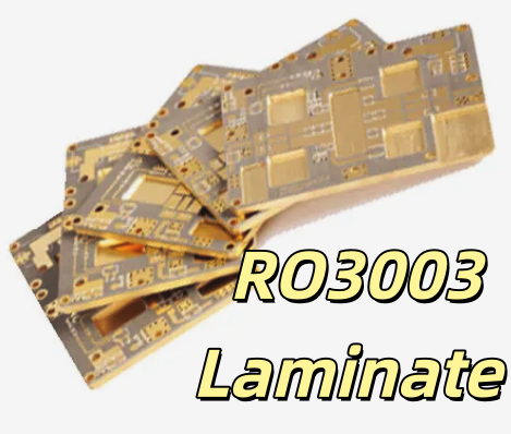
RO3003™ is a ceramic-filled PTFE laminate developed by Rogers Corporation for high-frequency RF and microwave applications. It offers one of the lowest dielectric loss values available in commercial PCB substrates, making it ideal for 5G, phased-array radar, aerospace communications, and precision antennas.
Key characteristics of RO3003:
- Ultra-low dielectric constant variation
- Low dissipation factor for minimal insertion loss
- Excellent dimensional stability and mechanical consistency
- Tight dielectric tolerance suitable for phase-critical designs
- Available in multiple thicknesses for impedance control
RO3003 is part of the Rogers 3000 series, designed specifically for high-frequency, high-reliability RF structures.
Features of Rogers RO3003
RO3003 laminate shows a unique blend of electrical and mechanical traits. These traits make the laminate one of the most trusted RF materials on the market.
- Stable Dielectric Constant
The dielectric constant stays around 3.00 ± 0.04 at 10 GHz. The tight tolerance helps maintain clean RF transmission lines. This is why many designers use ro3003 controlled impedance structures in radar filters and couplers.
- Very Low Dissipation Factor
The dissipation factor sits at 0.001 at 10 GHz. Low loss helps preserve signal strength and reduces heating in long RF paths.
- Low Moisture Absorption
Moisture absorption is around 0.04%. This helps keep the dielectric stable outdoors. It also reduces drift in sensitive antenna circuits.
- Consistent Mechanical Behavior
RO3003 laminate shows stable CTE values across X, Y, and Z directions. This supports fine-pitch drilling and strong via reliability.
- Supports High-Frequency Layout
Because of its low loss, ro3003 microwave laminate is a strong fit for 24 GHz sensors, 77 GHz radar, and mmWave imaging.
- Friendly for Hybrid Stackups
Designers often combine FR4 with ro3003 in a ro3003 hybrid stackup. This helps reduce cost without losing RF performance.
All these features help engineers build stable microwave systems with predictable behavior.
RO3003 Datasheet PDF Technical Overview
Below are the most referenced values from the official RO3003 datasheet:
| Parameter | Typical Value |
| Dielectric Constant (Dk 10 GHz) | 3.00 ±0.04 |
| Dissipation Factor (Df @ 10 GHz) | 0.0010 |
| Thermal Conductivity | 0.50 W/m·K |
| TCDk | +3 ppm/°C |
| Moisture Absorption | 0.04% |
| Decomposition Temperature (Td) | > 500°C |
| Density | 2.1 g/cm³ |
If you want to know more details about rogers RO3003 laminate datasheet, you can download it at below.

Rogers RO3003 Thickness Options
The Rogers RO3003 thickness lineup supports controlled impedance, multilayer RF boards, and antenna substrates:
Common RO3003 Thicknesses (inch/mm):
- 0.005” (0.13 mm) — (thin radar cores)
- 0.010” (0.25 mm)
- 0.015” (0.38 mm)
- 0.020” (0.50 mm)
- 0.025” (0.64 mm)
- 0.030” (0.76 mm) — (stable RF sub-assemblies)
- 0.060” (1.52 mm) — (antenna, coupler, and filter cores)
Thicker cores enable low-impedance RF lines, while thin cores support fine-pitch microwave structures (filters, couplers).
What Is the Thermal Conductivity of Rogers 3003?
RO3003 thermal conductivity = 0.50 W/m·K
This thermal conductivity is higher than traditional PTFE but lower than hydrocarbon-ceramic materials like RO4350B.
Effectively:
- Good for moderate-power RF
- Requires proper heatsinking & via-in-pad for high-power applications
How to Build Stable RF Structures With RO3003 Material?
Designers choose RO3003 material for its strong electrical stability, but the laminate reaches its best performance only when the RF layout follows a strict and systematic approach. The steps below describe how engineers build stable, low-loss, and repeatable RF structures using ro3003 pcb material.
1. Set a Consistent and Accurate RO3003 PCB Stackup
The stackup is the base of every RF design. Before placing any trace, define a stable ro3003 pcb stackup with fixed dielectric thickness and accurate copper weight.
RO3003 has a tight dielectric tolerance, so the main risk comes from variations in laminate thickness. A small shift in the core can move impedance away from your target value.
To avoid this:
- Pick one RO3003 thickness that matches your controlled impedance goals.
- Avoid mixing many thickness values in one project unless required.
- Confirm bonding films if you use a ro3003 hybrid stackup with FR4.
A clean, stable stackup is the first step toward building strong RF structures.
2. Use Copper with Low Roughness for Better High-Frequency Performance
At high frequencies, conductor loss increases as copper becomes rougher. When building a ro3003 microwave laminate design, choose a smoother copper option if your frequency moves above 10 GHz.
For mmWave devices, rolled copper gives better performance than standard ED copper.
Lower copper roughness leads to:
- Lower insertion loss
- More stable phase
- Improved 24 GHz and 77 GHz radar behavior
- Better antenna radiation when making ro3003 antenna pcb designs
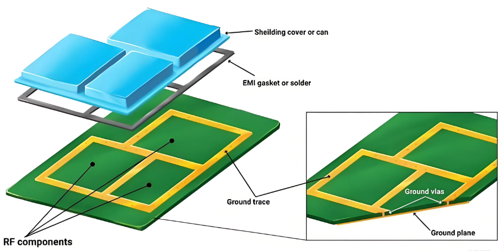
3. Build a Strong Ground Network to Stabilize Return Currents
A tight ground network provides:
- Lower radiation
- Lower signal reflection
- Better matching near connectors
- Stronger isolation between RF blocks
This is also critical when designing couplers, filters, and antennas on ro3003 pcb material.
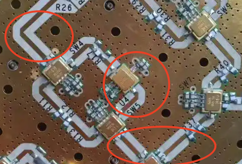
4. Keep RF Lines Short, Simple, and Smooth
Shorter RF paths produce lower loss, smooth curves reduce field disturbance and sharp 90° corners create reflections that shift impedance. In a detailed ro3003 pcb design, you should:
- Use soft bends or chamfered angles
- Keep trace width uniform along the entire length
- Avoid necking unless required by components
When traces stay short and smooth, phase stability remains high even in wide-band applications such as 5G or automotive radar.
5. Reduce Layer Transitions Whenever Possible
In mmWave systems built on ro3003 pcb material, a single via can change the response of a filter or antenna feed. To reduce problems, you can:
- Keep RF traces on one layer
- If you must transition, use back drilling
- Match the pad size to your simulation
- Surround the via with ground stitching vias
6. Match Connector Pads and Launch Geometry With Simulation
Connector transitions are the most sensitive part of many RF boards. A small mismatch on the connector pad can shift impedance and distort the feed. This is especially true for SMA, SMP, MCX, and UFL connectors.
Rogers RO3003 vs RO4003C vs RO4350B: What are Differences?
| Property | RO3003 | RO4003C | RO4350B |
| Dk | 3.00 | 3.55 | 3.48 |
| Df @ 10 GHz | 0.0010 (best) | 0.0027 | 0.0037 |
| Thermal Conductivity | 0.50 | 0.71 | 0.62 |
| Cost | High | Low | Medium |
| Max Frequency | ~40–100 GHz+ | ~10–20 GHz | ~20–30 GHz |
| Material Base | PTFE ceramic | Hydrocarbon | Hydrocarbon |
| Usage | Radar, mmWave | Routers, mid-RF | Power RF, telecom |
In summary
- RO3003 → Best for mmWave, radar, precision filters
- RO4003C → Cost-friendly for mid-RF hardware
- RO4350B → Good for RF power and backhaul radios
RO3003 is the preferred laminate for high-end millimeter-wave work where small shifts can damage system accuracy.
Popular Usage of RO3003 PCB
RO3003 laminate supports thousands of RF designs. The material functions well in any system where high stability and low loss matter, common usage including:
- 24 GHz radar modules
- 77 GHz vehicle radar
- Point-to-point microwave links
- Satellite receivers
- GPS L1/L2/L5 hardware
- Phased-array antennas
- RF filters and couplers
- RF measurement devices
- mmWave imaging systems
- High-frequency test boards
- 5G small cell antennas
- Imaging systems in security
- Precision measurement devices
- Millimeter-wave radar sensors
Many of these designs rely on mmwave ro3003 pcb material for consistent behavior in harsh environments.
Why Rogers 3003 Price Is Higher & How to Reduce It?
Rogers 3003 price is higher than RO4003C or FR-4 because of the PTFE-ceramic system and its strict manufacturing process. PTFE lamination requires special equipment and careful handling. The cost rises due to controlled sintering and slow processing cycles.
You can still lower the overall cost with smart design choices:
1. Use hybrid stack-ups (RO3003 for RF layers + FR-4 for digital layers).
2. Select thinner RO3003 where possible.
3. Optimize panel utilization to reduce waste.
4. Reduce layer transitions
5. Keep traces simple and consistent
6. Minimize layer count.
7. Discuss DFM steps early with the PCB manufacturer.
These steps help reduce cost without losing RF performance.
Fabrication Limits of RO3003 Material
RO3003 can be fabricated well in experienced RF PCB factories, but the material has special requirements.
Typical Fabrication Limits
| Parameter | Typical Limit |
| Minimum trace width | 3 mil (depends on copper) |
| Minimum spacing | 3 mil |
| Plated through-hole size | ≥0.2 mm |
| Laser microvia | Yes, but PTFE drilling needs caution |
| Hybrid lamination | Possible with bonding layers |
| Solder mask | Controlled to avoid impedance shift |
| Tolerance | ±10% or better for RF lines |
RO3003 PCB Layout Design Tips
- Keep RF lines straight
- Use smooth bends, not sharp corners
- Place ground stitching close to key lines
- Keep distance between RF and digital areas
- Use stable reference planes
- Match connector pads with simulation results
- Use isolation areas between sensitive blocks
Frequently Asked Questions About RO3003
1. Does RO3003 support mmWave?
Yes. Many mmwave ro3003 pcb systems use it at 24 GHz and 77 GHz.
2. Can RO3003 be mixed with FR4?
Yes. Designers use it in a ro3003 hybrid stackup to reduce cost.
3. Why is RO3003 expensive?
PTFE processing and ceramic filler raise the cost.
4. What is the loss tangent?
The loss tangent is 0.001 at 10 GHz.
5. Can RO3003 be used for antennas?
Yes. Its stable dielectric supports precise antennas.
Why Choose EBest Circuit (Best Technology) for RO3003 PCB Manufacturing?
RO3003 supports advanced RF structures where stability, low loss, and tight impedance are important. To reach the laminate’s full performance, you need a manufacturer with strong PTFE skills. EBest Circuit (Best Technology) offers stable fabrication lines, SI9000 modeling, clean etching control, and strict lamination parameters. We also hold ISO9001, ISO13485, IATF16949, and AS9100D certifications for high-reliability hardware.
We support ro3003 pcb fabrication, ro3003 hybrid stackup builds, radar module assembly, antenna PCBA, and full RF tuning. Our engineering team reviews your layout, stackup, and fabrication notes to help lower ro3003 pcb cost and improve long-term performance.