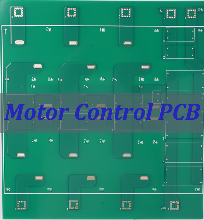
Motor Control PCB technology serves as the intelligent interface between command signals and physical motion, translating digital instructions into precise electrical currents that drive motors with exceptional accuracy and efficiency. These sophisticated circuit boards form the operational core of modern motion systems, balancing power delivery, thermal management, and signal integrity within increasingly compact form factors. This comprehensive guide explores the engineering principles, design methodologies, and practical implementation strategies that define advanced motor control PCB solutions, providing engineers and system designers with actionable insights for next-generation motion system development.
Are you struggling with motor control implementations that fail to deliver expected performance, reliability, or efficiency? Engineers developing motion systems consistently face several critical challenges:
- Thermal Management Difficulties: High-current operation generates excessive heat, leading to premature component failure and reduced lifespan without proper dissipation strategies.
- Electromagnetic Interference Issues: Switching noise from PWM signals disrupts sensitive control circuits, compromising precision in demanding applications.
- Space Constraints vs. Power Requirements: Shrinking form factors conflict with increasing power densities, creating engineering trade-offs that impact overall system performance.
- Signal Integrity Degradation: Mixed-signal environments where high-power switching noise corrupts low-voltage control signals, reducing positioning accuracy and control stability.
- Complex Implementation Barriers: Sophisticated control algorithms like FOC require specialized expertise and careful PCB layout, increasing development time and cost.
Modern motor control PCB technologies address these challenges through innovative engineering approaches:
- Advanced Thermal Management Architectures: Implementing thermal vias, copper pours, and strategic component placement to dissipate heat effectively, ensuring reliability under demanding operating conditions.
- Comprehensive EMI Reduction Techniques: Careful grounding strategies, component separation, and filtering methods that minimize electromagnetic interference, preserving signal integrity in noisy environments.
- High-Density Power Delivery Systems: Utilizing multilayer boards with dedicated power planes and optimized trace geometries to deliver substantial current within minimal board area.
- Mixed-Signal Layout Optimization: Implementing separation techniques and guard traces to isolate sensitive control signals from power switching noise, maintaining precision in challenging environments.
- Integrated Development Ecosystems: Combining hardware reference designs with software libraries and configuration tools that streamline implementation of advanced control methodologies.
At BEST Technology, we specialize in manufacturing advanced motor control PCBs that overcome these challenges through innovative engineering and precision manufacturing. Our expertise spans from basic DC motor controllers to complex multi-axis motion systems, ensuring optimal performance for your specific application requirements. For more information or if you would like to send us any inquiry, please send us an email through the contact form at the bottom of our Contact US Page.
What Is a Motor Control PCB?
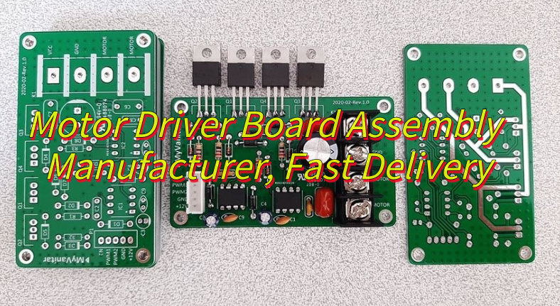
A motor control PCB is a specialized printed circuit board designed specifically to manage the electrical power delivered to an electric motor, translating command signals into precise motion output. These intelligent boards serve as the critical interface between low-power control systems (such as microcontrollers or processors) and the high-power demands of motors, enabling sophisticated control over speed, torque, position, and operational characteristics.
Unlike generic circuit boards, motor control PCBs incorporate several distinctive elements that make them uniquely suited for their role. They typically feature power transistors or MOSFETs capable of handling substantial currents, gate driver circuits for switching control, current sensing mechanisms for feedback, and protection circuits to prevent damage from overcurrent, overvoltage, or thermal overload conditions. The specific component selection and layout vary significantly depending on whether the board is designed for DC, stepper, or brushless DC (BLDC motor controller PCB) applications.
The fundamental importance of motor control PCBs in modern motion systems cannot be overstated. They enable the precision control necessary for applications ranging from delicate robotic surgery instruments to powerful industrial automation equipment. By implementing sophisticated control algorithms like Field-Oriented Control (FOC) and Space Vector PWM (SVPWM), these PCBs deliver smooth, efficient motor operation across speed and torque ranges that were previously unattainable with simpler control methods.
Table: Comparison of Motor Control PCB Types
| PCB Type | Typical Applications | Key Characteristics | Control Methodology |
|---|---|---|---|
| DC Motor Controller PCB | Toys, Pumps, Small Devices | H-bridge, PWM Control | Voltage & Direction |
| Stepper Motor Driver PCB | 3D Printers, CNC, Robotics | Microstepping, Phasing | Pulses & Current |
| BLDC Motor Controller PCB | Drones, EVs, Tools | 3-phase Bridge, Sensors | Commutation, FOC |
| PCB Stator Motor Controller | Robotics, Aerospace, Medical | Thin Design, High Precision | Digital & Adaptive |
The evolution of motor control circuit board PCB board technology continues to push the boundaries of what’s possible in motion control, with recent advancements incorporating wide-bandgap semiconductors (SiC and GaN), integrated motor-driver solutions, and advanced thermal management techniques that collectively enhance power density, efficiency, and reliability.

How Does a Motor Control Board Work?
A motor control board operates through a sophisticated interplay of power regulation, signal processing, and feedback mechanisms that collectively transform command signals into precise motor motion. At its core, the board functions as a translator and amplifier, converting low-power signals from a microcontroller or command source into the high-current, high-voltage signals necessary to drive motors effectively. This process involves multiple stages of signal conditioning, power switching, and real-time monitoring to ensure accurate and reliable operation.
The operational sequence begins when the board receives a command signal indicating the desired motor behavior (speed, position, or torque). This signal is processed by control logic, which determines the appropriate switching sequence for the power stage. The power stage then delivers energy to the motor windings in a carefully controlled manner, while feedback sensors continuously monitor actual motor performance. This feedback allows the control logic to make real-time adjustments, creating a closed-loop system that maintains the desired output despite variations in load or operating conditions.
Critical Components and Their Functions
Understanding the individual components that comprise a motor control board reveals how these systems achieve such precise control over electric motors:
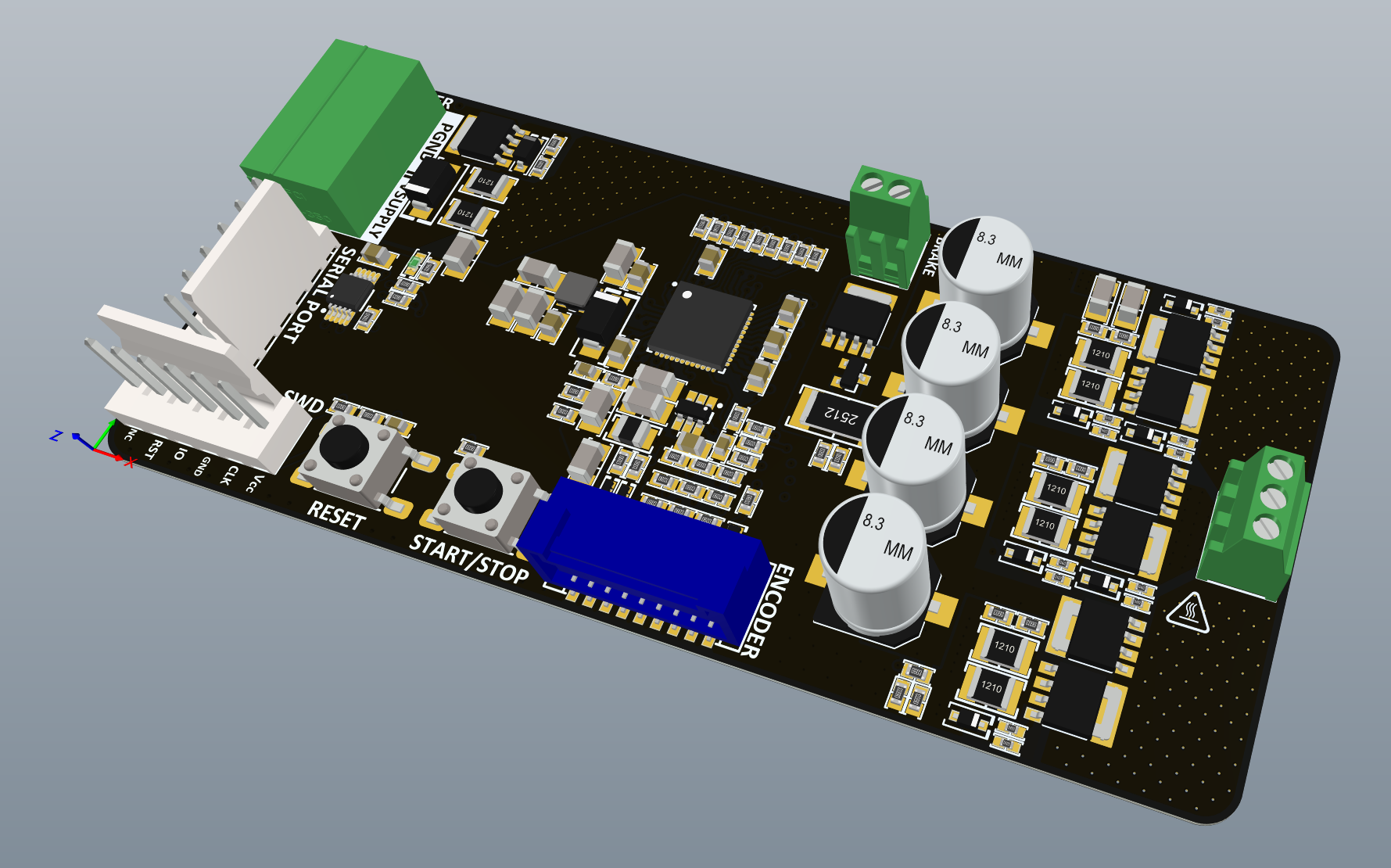
- Microcontroller/Processor: Serves as the intelligent core of the system, executing control algorithms (PID, FOC, etc.) and making real-time decisions based on sensor feedback and command inputs. Modern motor control boards often feature powerful 32-bit ARM Cortex-M processors capable of running advanced algorithms at high speeds.
- Gate Driver Circuits: Amplify low-power signals from the microcontroller to voltage and current levels sufficient to drive the power switches efficiently. These circuits ensure rapid switching of MOSFETs or IGBTs while providing necessary isolation and protection features.
- Power Switches (MOSFETs/IGBTs): Function as electronic valves that control power flow to the motor windings. The specific configuration (H-bridge for DC motors, three-phase bridge for BLDC motors) determines how the motor operates in terms of direction, speed, and torque generation.
- Current Sensing Circuits: Monitor electrical current flowing to the motor using shunt resistors, Hall effect sensors, or current transformers. This information is crucial for torque control and protection functions, enabling the implementation of advanced control strategies like Field-Oriented Control.
- Protection Circuits: Include overcurrent detection, overvoltage clamping, thermal monitoring, and undervoltage lockout mechanisms that safeguard both the control board and the motor from damage under fault conditions.
Control Methodologies and Signal Processing
Different motor types require distinct control approaches, which the motor control board implements through specialized circuitry and algorithms:
For DC motor speed control PCB applications, Pulse Width Modulation (PWM) is the predominant control strategy. The board varies the duty cycle of switching signals to effectively control the average voltage applied to the motor, thereby regulating speed. An H-bridge configuration enables bidirectional current flow, permitting both forward and reverse operation.
In brushless DC motor controller PCB systems, the control board must sequentially energize the motor phases in synchronization with rotor position. This requires either sensor-based feedback (from Hall effect sensors or encoders) or sensorless techniques that monitor back-EMF to determine commutation timing. Advanced boards implement Field-Oriented Control, which decouples torque and flux-producing currents for superior efficiency and dynamic response.
Stepper motor controllers employ a different approach, sending precise pulse sequences to advance the motor in discrete steps. Microstepping techniques subdivide these steps for smoother operation and reduced resonance, requiring sophisticated current control through each motor winding.
Table: Motor Control Board Signal Processing Stages
| Processing Stage | Function | Key Components |
|---|---|---|
| Command Input | Receives control signals | UART / SPI / CAN |
| Signal Conditioning | Filters input signals | Op-amps, RC parts |
| Control Algorithm | Computes motor output | MCU / DSP |
| PWM Generation | Creates timing pulses | PWM timers |
| Gate Driving | Drives power switches | Gate drivers |
| Feedback Acquisition | Reads motor feedback | ADCs, sensors |
The sophistication of modern motor control PCB board designs continues to evolve, with integrated solutions like Texas Instruments’ MCF8316C and MCF8315C devices combining control algorithms, gate drivers, and power stages into single-chip solutions that reduce design complexity while enhancing performance and reliability.
How Does a BLDC Motor Controller PCB Achieve Smooth and Precise Motor Operation?
A brushless DC motor controller PCB achieves exceptional smoothness and precision through sophisticated control algorithms that optimize performance across the entire operating range. The most significant advancement in BLDC control methodology is Field-Oriented Control (FOC), a technique that decouples the control of torque-producing and magnetic flux-producing components of motor current. This approach enables seamless operation similar to high-performance DC motors but with the efficiency benefits of brushless technology.
The FOC algorithm implementation on a BLDC motor controller PCB involves several computational stages. First, the controller measures two motor phase currents, deriving the third using Kirchhoff’s law. These measurements are transformed from a three-phase system to a two-axis rotating reference frame using the Clarke and Park transformations. This mathematical manipulation allows the controller to independently manage torque (q-axis) and flux (d-axis) components. After applying appropriate control strategies (typically PID controllers), the algorithm transforms the signals back to the three-phase domain for PWM generation.
Critical Sensor Integration and Feedback Mechanisms
Precision operation in BLDC motors relies heavily on accurate feedback systems integrated into the motor control PCB. Two primary sensing approaches dominate modern implementations:
Sensor-based systems utilize Hall effect sensors or encoders mounted within the motor to provide precise rotor position information. These sensors deliver digital or analog signals to the controller, enabling exact commutation timing. Encoders, especially absolute and multi-turn variants, offer the highest position resolution, making them ideal for applications requiring precise positioning such as robotic arms and CNC machines.
Sensorless control techniques have gained significant popularity for their reduced component count and cost advantages. These methods typically monitor the back-electromotive force (back-EMF) generated in the unenergized motor winding during operation. As the motor rotates, each winding generates a voltage proportional to speed, with zero-crossing points indicating commutation events. Advanced sensorless algorithms can achieve performance comparable to sensored systems, particularly at medium to high speeds.
PWM Techniques and Switching Optimization
The quality of BLDC motor operation heavily depends on the pulse-width modulation techniques employed by the controller PCB. Standard PWM methods have evolved to include sophisticated approaches that optimize switching patterns for reduced acoustic noise, improved efficiency, and smoother torque production:
- Sinusoidal PWM: Provides smooth sinusoidal current to the motor windings, reducing torque ripple and acoustic noise compared to traditional six-step commutation.
- Space Vector PWM (SVPWM): A more advanced technique that offers approximately 15% better DC bus utilization compared to sinusoidal PWM, resulting in higher torque output capabilities without increasing voltage requirements.
- Advanced Modulation Schemes: Techniques such as discontinuous PWM and third-harmonic injection further optimize switching losses and electromagnetic performance, particularly important in high-frequency applications.
The switching frequency selection represents a critical design trade-off. Higher frequencies (typically 20-100 kHz) move acoustic noise above the human hearing range and reduce current ripple but increase switching losses. Lower frequencies improve efficiency but may produce audible noise and require larger filtering components.
Implementation Considerations for Smooth Operation
Achieving truly smooth BLDC operation requires attention to several implementation details on the motor controller PCB:
- Current Sensing Accuracy is paramount for precise torque control. High-quality sampling circuits with adequate resolution (typically 12-16 bits), proper filtering, and careful layout ensure accurate current measurements. Multiple sampling techniques including low-side, high-side, and inline resistor configurations each offer distinct advantages for different applications.
- Dead Time Insertion prevents shoot-through currents that can damage power switches during phase transitions. However, improper dead time compensation introduces distortion, so modern controllers implement adaptive compensation techniques that maintain waveform integrity while ensuring safety.
- Startup and Low-Speed Optimization presents particular challenges, especially for sensorless designs that rely on back-EMF measurement. Advanced startup sequences typically begin with rotor alignment followed by open-loop acceleration until sufficient back-EMF develops for transition to closed-loop operation. Sophisticated algorithms smoothly manage this transition to prevent stalling or hesitation.
The integration of these techniques in modern BLDC motor controller PCB designs enables remarkable performance characteristics, with efficiency levels exceeding 90% and torque ripple reduced to less than 2% in optimized implementations.
What Design Principles Ensure a Stable and Efficient Motor Driver PCB and Motor Controller PCB Layout?
The foundation of a stable motor driver PCB begins with strategic component placement that segregates circuits based on their signal characteristics and power requirements. Effective partitioning separates high-power switching sections (containing MOSFETs/IGBTs and gate drivers) from sensitive analog and digital control circuits, minimizing noise coupling and ensuring signal integrity.
A well-designed motor controller PCB layout follows a logical flow from power input to motor output, with components arranged to minimize current path lengths and loop areas. The power stage components should be clustered together, with gate drivers positioned immediately adjacent to their corresponding power switches to keep gate drive traces short (typically <15mm). This placement strategy reduces parasitic inductance that can cause voltage spikes and switching artifacts.
Critical to this partitioning approach is the establishment of distinct functional zones:
- Power Input Section: Where bulk capacitors and filtering components are located near power connectors
- Switching Power Stage: Containing MOSFETs/IGBTs and gate drivers in a compact arrangement
- Control Section: Housing the microcontroller and support components in a quiet area of the board
- Feedback Circuits: Positioning current sensors and analog conditioning circuits away from noise sources
- Communication Interfaces: Isolating sensitive digital interfaces from power switching noise
Power Delivery System Design
A robust power delivery system is essential for motor driver PCB stability and efficiency. This begins with appropriate PCB layer stackup design, where multi-layer boards (typically 4-6 layers) provide dedicated power and ground planes that offer low-impedance current paths and excellent noise suppression.
The power delivery network must be designed to handle both continuous and peak current demands without excessive voltage drop or heating. Trace width calculations based on current requirements are critical, with external layers capable of carrying approximately 30-50% more current than internal traces of the same width due to better heat dissipation. For high-current applications (typically >5A), 2oz or heavier copper is recommended to reduce resistance and improve current-handling capability.
Table: PCB Trace Width Recommendations for Motor Control Applications
| Current (A) | 1oz Copper (10°C rise) | 2oz Copper (10°C rise) | 1oz Copper (20°C rise) | 2oz Copper (20°C rise) |
|---|---|---|---|---|
| 5A | 1.2mm (47 mil) | 0.6mm (24 mil) | 0.8mm (31 mil) | 0.4mm (16 mil) |
| 10A | 3.0mm (118 mil) | 1.5mm (59 mil) | 2.0mm (79 mil) | 1.0mm (39 mil) |
| 20A | 8.5mm (335 mil) | 4.2mm (165 mil) | 5.5mm (217 mil) | 2.8mm (110 mil) |
| 30A | 15.0mm (591 mil) | 7.5mm (295 mil) | 10.0mm (394 mil) | 5.0mm (197 mil) |
Decoupling capacitor placement significantly impacts high-frequency performance. Small ceramic capacitors (100nF-1μF) should be located as close as possible to IC power pins, with larger bulk capacitors (10-100μF) distributed throughout the board to maintain stable voltage during transient loads.
Thermal Management Strategies
Effective thermal management is non-negotiable for reliable motor control PCB operation. Power dissipation in switching components and current-carrying traces generates heat that must be efficiently conducted away from critical components to prevent thermal runaway and ensure long-term reliability.
Several techniques contribute to optimal thermal performance:
- Thermal Via Arrays: Placing multiple vias (typically 0.3-0.5mm diameter) beneath power component thermal pads conducts heat to inner and opposite copper layers, significantly improving heat dissipation. These vias should be filled with thermal epoxy or solder for optimal thermal transfer.
- Copper Pour Utilization: Large copper areas connected to power components act as heat spreaders, increasing surface area for convective cooling. The effectiveness of these pours depends on their size, connection method, and exposure to airflow.
- Component Placement Considerations: Distributing heat-generating components across the board prevents localized hot spots. When high-power components must be clustered, additional cooling measures such as heatsinks or forced airflow are necessary.
- Thermal Interface Materials: Selecting appropriate thermal compounds, pads, or phase-change materials between components and heatsinks minimizes thermal resistance, improving heat transfer efficiency.
For applications with extreme power demands, metal-core PCBs (MCPCB) provide superior thermal conductivity compared to standard FR-4 substrates, though at increased cost and manufacturing complexity.
Grounding and EMI Control Techniques
Proper grounding strategies form the foundation of EMI control in motor driver PCB designs. A single, continuous ground plane is generally preferred over multiple segmented grounds, as it provides a low-impedance return path and minimizes ground bounce.
When dealing with mixed-signal designs containing analog, digital, and power sections, the ground plane separation approach must be carefully considered. While complete separation seems intuitively correct, it can create more problems than it solves by forcing return currents to take longer paths, increasing loop areas and EMI radiation. A better approach maintains a unified ground plane with careful component placement to prevent noise coupling.
Additional EMI reduction techniques include:
- Guard Traces: Placing grounded copper barriers between noisy and sensitive circuits provides additional isolation.
- Filtering Networks: Implementing RC filters on sensitive analog inputs and motor feedback signals suppresses high-frequency noise.
- Proper Shielding: Using shielded cables for external connections and incorporating shielded compartments for particularly sensitive circuits.
- Slowing Switching Edges: Adding small resistors (2-10Ω) in series with gate drive paths reduces dv/dt, decreasing EMI generation at the cost of slightly increased switching losses.
By implementing these design principles, motor controller PCB layout can achieve the stability and efficiency required for demanding motion control applications, ensuring reliable operation across diverse operating conditions.
How Does a DC Motor Speed Control PCB Regulate Speed, Torque, and Power Output?
The primary method employed by a DC motor speed control PCB to regulate motor velocity is Pulse Width Modulation (PWM), a technique that varies the average voltage applied to the motor by switching power to the load at a high frequency with adjustable duty cycles. Rather than delivering a variable analog voltage, the controller rapidly switches full power on and off, with the proportion of on-time to off-time (duty cycle) determining the effective voltage seen by the motor.
The PWM frequency selection represents a critical design decision that balances several factors. Lower frequencies (typically 1-5 kHz) are more efficient with lower switching losses but may produce audible noise and result in larger current ripple. Higher frequencies (20-50 kHz) move the switching noise above the audible range and reduce current ripple but increase switching losses in the power devices. Modern DC motor controller PCB designs typically operate in the 15-25 kHz range, optimizing both acoustic performance and efficiency.
The implementation of PWM control involves an H-bridge configuration comprising four power switches (usually MOSFETs) arranged in a bridge configuration. This arrangement allows bidirectional current flow through the motor, enabling both forward and reverse operation. By controlling the switching sequence of these four devices, the controller can apply positive voltage, negative voltage, or brake the motor by shorting its terminals.
Torque Control and Current Regulation
Beyond basic speed control, advanced DC motor speed control PCB designs implement precise torque regulation through current control techniques. Since motor torque is directly proportional to armature current, measuring and controlling current enables accurate torque management essential for applications like robotic arms, conveyor systems, and precision tools.
Current sensing typically employs one of several methods:
- Shunt Resistors: Low-value, high-precision resistors placed in series with the motor current path, with the voltage drop across the resistor proportional to current. This method offers excellent accuracy and bandwidth but introduces power losses.
- Hall Effect Sensors: Magnetic field sensors that measure current without direct electrical connection, providing isolation and minimal insertion loss. These are preferred for higher-current applications but are more expensive and may have limited bandwidth.
- Current Transformer: Used for AC current measurement, these provide inherent isolation but are unsuitable for DC measurement without additional circuitry.
Once measured, the current feedback is compared to a torque command, with the error processed by a PI controller that adjusts the PWM duty cycle to maintain the desired current level. This closed-loop current control enables precise torque regulation even as motor back-EMF varies with speed.
Power Output Optimization and Efficiency Considerations
Efficient power delivery is a hallmark of well-designed DC motor controller PCB systems. Several techniques contribute to optimized power output:
- Synchronous Rectification significantly improves efficiency in PWM motor drives. During the off-time of the PWM cycle, the motor’s inductance causes current to continue flowing through the body diodes of the MOSFETs. By intentionally turning on the appropriate MOSFETs during this period (synchronous conduction), the voltage drop reduces from approximately 0.7V (diode forward voltage) to just the MOSFET’s RDS(ON) voltage drop, typically 0.05-0.10V for modern devices. This reduction in voltage drop decreases power losses, particularly at light loads where conduction time is short.
- Dead Time Management addresses a potential issue in H-bridge operation. To prevent shoot-through currents (both high-side and low-side switches on simultaneously), a small dead time is inserted between turning one switch off and turning the complementary switch on. However, improper dead time causes distortion at zero-current crossings and reduces effective voltage. Advanced controllers implement adaptive dead time compensation to minimize these effects.
- Supply Voltage Compensation maintains consistent performance across varying input voltages. As battery voltage declines in portable applications or line voltage fluctuates in stationary systems, the PWM duty cycle requires adjustment to maintain the same effective motor voltage. Sophisticated controllers incorporate input voltage monitoring and automatic compensation.
Advanced Control Algorithms for Enhanced Performance
While basic PWM control suffices for many applications, advanced DC motor speed control PCB implementations employ sophisticated algorithms for superior performance:
- PID Speed Control combines proportional, integral, and derivative terms to achieve precise speed regulation. The proportional term responds to immediate error, the integral term eliminates steady-state error, and the derivative term improves response to changing loads. Carefully tuned PID controllers maintain consistent speed despite varying mechanical loads.
- Adaptive Control techniques automatically adjust control parameters as operating conditions change. For example, the controller might recognize that higher torque levels require different gain settings to maintain stability, or that motor characteristics change with temperature, necessitating corresponding adjustments to the control strategy.
- Field-Weakening Control extends the speed range beyond the motor’s base speed. In permanent magnet DC motors, back-EMF limits the maximum speed at which the motor can be driven with available voltage. By intentionally reducing the magnetic flux (in wound-field motors) or applying advanced current phase control (in BLDC motors), the controller can achieve higher speeds at the expense of reduced torque capability.
These advanced control techniques, implemented through sophisticated motor control PCB programming, enable DC motor controllers to deliver precise, efficient, and responsive performance across a wide range of operating conditions and application requirements.
What Makes PCB Stator Motor Technology Unique and How Does It Expand PCB Motor Application?
PCB Stator motor technology represents a revolutionary approach to electric motor design that replaces traditional copper wire windings with precision-etched printed circuit boards as the stator component. This innovative methodology leverages printed circuit board manufacturing techniques to create intricate, multilayer stator structures that offer significant advantages over conventional motor construction.
The core innovation lies in the replacement of hand-wound or machine-wound copper coils with photolithographically defined traces on a rigid or flexible PCB substrate. These traces form the motor windings with exceptional precision and consistency, eliminating the variations and imperfections inherent in traditional winding processes. The resulting stator is dramatically thinner and lighter than conventional designs while maintaining excellent electromagnetic performance.
A key differentiator of PCB Stator motor technology is its integration of the motor drive and control electronics directly onto the stator PCB itself. This integration creates a compact, unified system that reduces the overall footprint and eliminates many of the interconnects that can introduce reliability issues in traditional motor systems. The approach enables unprecedented levels of miniaturization while maintaining high power density.
Performance Advantages and Technical Superiority
The unique characteristics of PCB Stator motor design translate into several compelling performance advantages that expand potential applications:
- Exceptional Power Density is perhaps the most significant benefit, with PCB stator motors delivering up to 70% weight reduction and 50% size reduction compared to conventional motors of equivalent power output. This dramatic improvement stems from the elimination of bulky copper windings and the integration of control electronics within the motor structure itself.
- Superior Efficiency results from the precise control over trace geometry and the ability to optimize the winding pattern for specific operating conditions. PCB stator motors achieve efficiencies exceeding 90% across a broad operating range, with some implementations reaching 95% efficiency in targeted applications. This efficiency advantage translates to reduced energy consumption and less waste heat generation.
- Acoustic Performance improvements are another notable benefit. The absence of cogging torque (due to the slotless design) and the precision of the magnetic circuit result in exceptionally quiet operation with near-zero acoustic signature. This characteristic makes PCB stator motors ideal for applications where noise is a critical concern.
- Thermal Management advantages arise from the distributed nature of the windings across the PCB substrate, which provides a large surface area for heat dissipation. Additionally, the integration of thermal vias and the ability to incorporate heatsinking directly into the PCB structure enable effective cooling in high-power-density applications.
Expanded Application Horizons
The unique properties of PCB Stator motor technology open up new application possibilities that were previously challenging or impossible with conventional motor technologies:
- Aerospace and Aviation applications benefit tremendously from the weight reduction and compact form factors. Drones, electric aircraft, and satellite systems can achieve significant performance improvements through the integration of PCB stator motors, where every gram of weight reduction translates to extended flight time or increased payload capacity.
- Medical Devices represent another promising application area, where the combination of compact size, quiet operation, and precision control aligns perfectly with requirements for surgical robots, diagnostic equipment, and portable medical devices. The ability to create custom motor geometries enables integration into space-constrained medical instruments.
- Robotics and Automation systems gain advantages from the high torque density and precise control capabilities of PCB stator motors. Collaborative robots, in particular, benefit from the compact dimensions and excellent torque responsiveness, enabling more natural and safer human-robot interaction.
- Consumer Electronics and Internet of Things (IoT) devices represent emerging application areas where the small form factor, quiet operation, and efficiency of PCB stator motors enable new product categories and enhanced functionality in existing products.
Integration with Advanced Control Systems
The PCB Stator motor design naturally complements advanced control methodologies, particularly when integrated with sophisticated motor control PCB electronics. The precise, predictable electromagnetic characteristics of PCB stators enable implementation of advanced control algorithms with exceptional accuracy.
ECM’s “Eight Ball” servo motor exemplifies this integration, combining a 50:1 harmonic drive with a PCB stator motor and dual encoder feedback system. This configuration delivers remarkable performance characteristics: 33.9 Nm peak torque and 18.8 Nm continuous torque in a package weighing just 0.57 kg with dimensions of 2.95″ × 3.35″ × 1.96″. Such performance would be difficult or impossible to achieve with conventional motor technologies.
The PrintStator Motor CAD platform further enhances the capabilities of PCB stator technology by enabling digital motor design and optimization. This software-driven approach allows engineers to create custom motor solutions tailored to specific application requirements, significantly reducing development time and cost while optimizing performance.
As PCB Stator motor technology continues to evolve, it promises to redefine the possibilities for electric motion systems across an expanding range of industries and applications, offering unprecedented combinations of performance, efficiency, and compactness.
How Do OEM Motor Control Circuit Board PCB Board Manufacturers Guarantee Reliability and Quality?
OEM motor control circuit board PCB board manufacturers implement rigorous design validation processes to ensure reliability before production begins. These processes involve simulation and modeling of electrical, thermal, and mechanical performance under various operating conditions. Advanced software tools simulate power integrity, signal integrity, and thermal behavior, identifying potential issues early in the design phase when corrections are most cost-effective.
A key aspect of design validation is Design for Manufacturability (DFM) analysis, which identifies potential production issues before tooling begins. DFM checks ensure that the PCB design complies with manufacturing capabilities regarding minimum trace widths, spacing, hole sizes, and other geometric constraints. Similarly, Design for Assembly (DFA) analysis optimizes component placement and orientation for efficient, reliable assembly, considering factors such as solder joint quality, thermal management during reflow, and accessibility for automated testing.
Design for Testability (DFT) represents another critical validation aspect, incorporating test points, boundary scan capabilities, and other features that facilitate comprehensive testing during manufacturing. These features enable manufacturers to verify proper component operation and interconnection before the board reaches customers, catching defects early in the production process.
Advanced Manufacturing Techniques and Quality Control
The manufacturing process for motor control circuit board PCB board products incorporates multiple quality assurance checkpoints to maintain consistent quality:
Material Selection forms the foundation of reliability. High-temperature FR-4 substrates with appropriate Tg (glass transition temperature) values are essential for motor control applications where components may operate at elevated temperatures. For high-power applications, manufacturers often recommend heavy copper PCBs (2-6 oz) to handle high currents without excessive heating.
- Precision Fabrication processes ensure dimensional accuracy and consistency. Laser direct imaging (LDI) systems achieve finer trace geometries than traditional photolithography, while automated optical inspection (AOI) systems verify critical dimensions and detect defects such as shorts, opens, or insufficient spacing.
- Component Sourcing and Verification plays a crucial role in reliability. Established manufacturers maintain relationships with authorized distributors of reputable components, avoiding counterfeit parts that plague the electronics industry. Incoming components undergo verification testing, particularly for critical components such as power semiconductors that directly impact product reliability.
Table: Quality Control Checkpoints in Motor Control PCB Manufacturing
| Manufacturing Stage | Quality Control Measures | Purpose |
|---|---|---|
| Material Preparation | Material certification, thermal analysis | Verify substrate and copper quality |
| PCB Fabrication | Automated Optical Inspection (AOI), electrical testing | Detect manufacturing defects |
| Component Placement | Solder paste inspection, component verification | Ensure proper placement and orientation |
| Reflow Soldering | Thermal profiling, post-reflow inspection | Verify proper solder joints |
| Final Assembly | Functional testing, burn-in (if required) | Validate performance under operating conditions |
Comprehensive Testing Methodologies
Reliability assurance continues with rigorous testing protocols that evaluate motor control PCB performance under simulated operating conditions:
- In-Circuit Testing (ICT) verifies the presence, orientation, and value of components, while also checking for shorts and opens in the circuitry. Fixture-based ICT systems make contact with test points throughout the board, providing comprehensive electrical verification.
- Functional Testing subjects the completed motor control board to simulated operating conditions, applying power and control signals while monitoring outputs. This testing validates that the board performs its intended functions correctly, including proper motor driving, feedback sensing, and protection features.
- Environmental Stress Screening exposes boards to accelerated aging conditions such as thermal cycling, vibration, and humidity. Highly reliable applications may require Highly Accelerated Life Testing (HALT) or Highly Accelerated Stress Screening (HASS) to identify potential failure mechanisms and verify robustness.
- Burn-in Testing operates boards at elevated temperatures and voltages for extended periods to identify infant mortality failures before products ship to customers. This process is particularly important for applications where reliability is critical, such as automotive, medical, or industrial systems.
Reliability Certification and Continuous Improvement
Reputable OEM motor control circuit board PCB board manufacturers maintain certifications that demonstrate their commitment to quality and reliability. ISO 9001 quality management system certification ensures consistent processes and continuous improvement, while IATF 16949 is essential for automotive applications. Specific industry certifications such as ISO 13485 for medical devices or AS9100 for aerospace applications may be required for specialized markets.
Failure Analysis capabilities complement these certifications, enabling manufacturers to investigate any field returns or test failures to determine root causes and implement corrective actions. This closed-loop process drives continuous improvement in both design and manufacturing, enhancing reliability over successive product generations.
By implementing these comprehensive approaches to reliability and quality, reputable manufacturers deliver motor control PCBs that meet the demanding requirements of modern motion control applications, ensuring long-term performance and customer satisfaction.
How Does Motor Control PCB Programming Optimize 12V and High-Power Motor Systems?
Motor control PCB programming creates the intelligent layer that optimizes performance across varying voltage domains, from compact 12V systems to high-power industrial applications. The firmware architecture typically implements a modular structure that separates hardware abstraction, control algorithms, and application logic, enabling code reuse across different motor platforms while maintaining optimization for specific operating conditions.
For 12V motor control PCB applications, typically found in automotive, robotics, and consumer products, programming focuses on efficiency optimization due to often limited power availability. These implementations emphasize low quiescent current, sleep modes, and efficient startup sequences to minimize power consumption during idle periods. The code manages trade-offs between performance and battery life, implementing adaptive algorithms that adjust behavior based on available voltage and load conditions.
High-power systems, in contrast, prioritize thermal management and protection mechanisms in their programming. Firmware for these applications incorporates comprehensive monitoring of temperature, current, and voltage parameters, dynamically adjusting operation to prevent damage under fault conditions. Advanced implementations may include model predictive control algorithms that anticipate thermal behavior and adjust control parameters preemptively to maintain safe operating temperatures.
Advanced Control Algorithm Implementation
The sophistication of modern motor control PCB programming enables implementation of advanced algorithms that optimize performance across diverse operating conditions:
- Field-Oriented Control (FOC) represents the gold standard for brushless motor control, particularly in high-performance applications. This algorithm decouples the control of magnetic flux and torque-producing current components, enabling seamless operation similar to separately excited DC motors. FOC implementation requires substantial computational resources, typically running on 32-bit ARM Cortex-M processors with hardware acceleration for mathematical transformations.
- Sensorless Control Techniques eliminate the need for physical position sensors, reducing cost and improving reliability. These algorithms estimate rotor position by monitoring back-EMF in undriven motor phases, with sophisticated variants incorporating High-Frequency Injection for position estimation at standstill and low speeds. The programming must seamlessly transition between different estimation techniques as speed increases, maintaining stability across the entire operating range.
- Adaptive PID Tuning addresses the challenge of maintaining optimal control performance as motor characteristics change with operating conditions. Rather than using fixed PID gains, adaptive implementations continuously adjust proportional, integral, and derivative parameters based on observed performance. Some advanced systems implement self-tuning algorithms that automatically determine optimal PID parameters during commissioning or operation.
Performance Optimization Strategies
Motor control PCB programming implements various strategies to optimize specific aspects of motor performance:
- Efficiency Optimization focuses on minimizing losses across the operating range. Techniques include phase advance optimization for brushless motors, which adjusts the timing of commutation events to maximize torque per amp, particularly at high speeds. Maximum Torque Per Ampere (MTPA) algorithms continuously optimize current angle to achieve the highest possible efficiency for a given torque output.
- Acoustic Noise Reduction is critical for applications where silent operation is important. Programming techniques include PWM frequency modulation to spread acoustic energy across a broader frequency spectrum, reducing perceptible noise. Smooth commutation transitions through sinusoidal drive or advanced modulation schemes also minimize audible vibration caused by torque ripple.
- Torque Ripple Minimization enhances smoothness, particularly at low speeds where ripple is most noticeable. Advanced implementations employ iterative learning control or repetitive control techniques that identify periodic disturbances in the torque output and generate compensating signals to cancel them.
Protection and Diagnostic Features
Comprehensive protection mechanisms are essential components of motor control PCB programming, particularly for high-power systems where faults can have serious consequences:
- Real-Time Fault Detection algorithms monitor current, voltage, temperature, and position signals continuously, comparing them against predefined thresholds. When anomalies are detected, the firmware initiates appropriate responses, ranging from controlled shutdowns to graceful performance reduction, depending on the severity of the fault.
- Predictive Maintenance capabilities represent an advanced feature in modern motor controllers. By tracking operating hours, temperature profiles, and load cycles, the firmware can estimate component aging and predict potential failures before they occur. This information enables proactive maintenance, reducing downtime in critical applications.
- Commissioning and Diagnostics routines simplify setup and troubleshooting. Automated commissioning sequences characterize motor parameters upon initial installation, determining electrical and mechanical properties that optimize control parameters. Comprehensive diagnostic capabilities provide detailed information about system status and historical performance, facilitating troubleshooting and reducing mean time to repair.
Through these sophisticated programming approaches, modern motor control PCBs deliver optimized performance across diverse applications, from precision 12V systems to high-power industrial drives, maximizing efficiency, reliability, and functionality.
How to Test a Motor Control Circuit?
Testing a motor control circuit requires a systematic approach that progresses from basic validation to comprehensive performance characterization under simulated operating conditions. A well-structured testing regimen ensures reliability, safety, and performance compliance with design specifications.
The testing process typically begins with static measurements without power applied, progresses to power-on functional verification, and culminates in dynamic performance testing under load. At each stage, specific parameters are measured and compared against expected values, with deviations triggering investigation and corrective action.
Essential Test Equipment and Setup
Proper test equipment selection is crucial for accurate motor control circuit evaluation:
- Oscilloscope: A minimum 100MHz bandwidth digital oscilloscope with multiple channels is essential for observing PWM signals, current waveforms, and timing relationships. High-voltage differential probes are necessary for safely measuring switching waveforms in high-voltage circuits.
- Programmable Power Supply: A DC power supply capable of delivering the expected voltage and current ranges while providing measurement readbacks enables controlled power application during testing.
- Electronic Load or Dynamometer: For testing under realistic load conditions, an electronic load or mechanical dynamometer applies controllable torque to the motor, allowing performance characterization across the operating range.
- Current Probes: High-bandwidth current probes (Hall effect or Rogowski coil) accurately capture motor phase currents without introducing significant resistance or disturbing the circuit.
- Thermal Measurement Equipment: Infrared thermometers or thermal cameras provide non-contact temperature measurements of critical components during operation.
- Data Acquisition System: For comprehensive testing, a multi-channel DAQ system records voltage, current, temperature, and speed measurements simultaneously, enabling detailed performance analysis.
Step-by-Step Testing Procedure
A methodical approach to motor control circuit testing ensures thorough validation:
1. Visual Inspection and Continuity Testing
- Before applying power, conduct a thorough visual examination of the PCB for manufacturing defects such as solder bridges, missing components, or physical damage. Follow with continuity testing to verify proper connections and absence of shorts, particularly between power rails and ground.
2. Power-Up and Quiescent Current Measurement
- Apply low voltage (e.g., 5V) to the control circuitry first, measuring quiescent current to detect potential short circuits. Gradually increase voltage to nominal levels while monitoring current draw, ensuring values align with expectations based on the design.
3. Control Signal Verification
- With power applied but motor disconnected, verify proper operation of control interfaces. Apply command signals (PWM, analog voltage, or digital commands) and observe the resulting gate drive signals using an oscilloscope. Check for correct timing, amplitude, and waveform characteristics.
4. Gate Drive Signal Analysis
- Examine gate drive waveforms for proper shape, rise/fall times, and absence of ringing or oscillations. Excessive ringing indicates layout issues or inadequate gate resistance. Verify that dead time insertion prevents shoot-through in bridge configurations.
5. No-Load Motor Testing
- Connect the motor without mechanical load and apply gradually increasing commands. Monitor motor acceleration, listening for unusual noises and observing current draw. For BLDC motors, verify smooth rotation throughout the speed range, particularly during startup.
6. Protection Circuit Validation
Test each protection feature individually:
- Overcurrent Protection: Momentarily apply excessive load or simulate overcurrent condition to verify shutdown response
- Overvoltage/Undervoltage Protection: Vary supply voltage to trigger protection circuits
- Thermal Protection: Use a heat gun or similar to raise component temperatures while monitoring protection response
7. Dynamic Performance Characterization
Under controlled load conditions, measure:
- Efficiency: Power input versus mechanical power output across speed and torque range
- Speed Regulation: Ability to maintain set speed under varying loads
- Torque Response: Step changes in torque demand and response characteristics
- Thermal Performance: Temperature rise of critical components during continuous operation
Table: Motor Control Circuit Performance Metrics and Test Conditions
| Performance Metric | Test Condition | Acceptance Criteria |
|---|---|---|
| Startup Reliability | Multiple start-stop cycles at various positions | Smooth rotation without hesitation |
| Speed Regulation | ±50% load variation at constant speed command | <2% speed deviation |
| Efficiency | 25%, 50%, 75%, 100% of rated load | >85% (varies by motor type and power) |
| Thermal Stability | 2 hours at rated load | Temperature stabilization below maximum ratings |
| Audible Noise | Entire speed range at light load | <45 dBA at 1 meter distance |
Advanced Testing Techniques
For comprehensive validation, several advanced testing approaches provide deeper insights:
- Loop Response Analysis characterizes the control system’s stability and response characteristics. Using a frequency response analyzer or specialized software, inject a small signal perturbation into the control loop and measure the system’s response. This analysis verifies phase and gain margins, ensuring stable operation under all conditions.
- EMI/EMC Pre-compliance Testing identifies potential electromagnetic interference issues before formal certification testing. Using a spectrum analyzer with near-field probes, scan the operating circuit for emissions hotspots. This preliminary testing allows design modifications before costly formal testing.
- Accelerated Life Testing subjects the motor control circuit to elevated stress levels (temperature, voltage, vibration) to identify potential failure mechanisms and estimate product lifetime under normal operating conditions. While requiring specialized equipment, this testing provides valuable reliability data.
By following this comprehensive testing methodology, engineers can thoroughly validate motor control circuit performance, ensuring reliability, safety, and compliance with design specifications before deployment in field applications.
How Can You Choose the Best Motor Control PCB Supplier for High-Performance Motion Control Projects?
Selecting the optimal motor control PCB supplier requires careful evaluation of technical capabilities aligned with your project requirements. The assessment should include design expertise specific to motor control applications, as general PCB manufacturers may lack specialized knowledge about high-current layouts, EMI mitigation, and thermal management challenges unique to motion systems.
Key technical considerations include:
- Power Electronics Experience: Evaluate the supplier’s track record with similar power levels and motor types. High-performance applications demand expertise in layout techniques that minimize parasitic inductance, optimize switching performance, and manage high-current paths effectively. Request case studies or reference designs demonstrating their capability with projects of similar complexity.
- Signal Integrity Capabilities: For precision motion control, the supplier must demonstrate expertise in mixed-signal layout strategies that protect sensitive analog measurements (current sensing, position feedback) from digital noise and power switching artifacts. This includes proper grounding techniques, component separation, and filtering implementation.
- Thermal Management Expertise: Assess the supplier’s approach to heat dissipation, particularly for high-power designs. Look for experience with thermal vias, copper balancing, substrate selection, and integration of heatsinks or other cooling methods. The ideal supplier should provide thermal simulation results validating their design approach.
Manufacturing and Quality Assurance Evaluation
The supplier’s manufacturing capabilities and quality systems directly impact the reliability and performance of your motor control PCB:
- Certifications and Standards Compliance: Reputable suppliers maintain relevant quality certifications such as ISO 9001 for quality management systems and IATF 16949 for automotive applications. Industry-specific certifications may be necessary for medical, aerospace, or military applications.
- Testing and Validation Capabilities: Inquire about the supplier’s in-house testing facilities. Look for automated optical inspection (AOI), in-circuit testing (ICT), functional testing, and environmental stress screening capabilities. Suppliers with robust testing protocols can identify potential issues before boards ship.
- Supply Chain Management: Evaluate the supplier’s component sourcing practices and relationships with reputable distributors. Established suppliers have reliable access to genuine components, reducing the risk of counterfeit parts affecting your product’s reliability.
Design Support and Collaboration Approach
The level of design support offered by a motor control PCB supplier significantly influences project success, particularly for complex motion control applications:
- Engineering Support Availability: Determine whether the supplier provides dedicated engineering resources to assist with design optimization, component selection, and layout review. Early collaboration can prevent costly revisions and improve performance.
- Design for Manufacturability Feedback: The ideal supplier offers comprehensive DFM analysis, providing specific recommendations to improve manufacturability, reliability, and cost-effectiveness without compromising performance.
- Prototyping and NPI Services: Evaluate the supplier’s rapid prototyping capabilities and new product introduction process. Efficient prototyping services allow for quick design validation and iteration, accelerating time to market.
Cost Structure and Business Factors
While technical capabilities are paramount, business considerations also influence supplier selection:
- Pricing Transparency: Seek suppliers with clear, detailed pricing models that account for setup charges, tooling costs, and volume breaks. Beware of unusually low bids that may indicate compromised quality or hidden costs.
- Manufacturing Scalability: Ensure the supplier can accommodate production volumes from prototyping through mass production without compromising quality or lead times. Scalable suppliers grow with your business needs.
- Communication and Project Management: Evaluate the supplier’s communication responsiveness, language capabilities, and project management approach. Regular progress updates and clear points of contact facilitate smooth collaboration.
Table: Motor Control PCB Supplier Evaluation Criteria
| Evaluation Category | Key Assessment Factors | Ideal Supplier Characteristics |
|---|---|---|
| Technical Capability | Power design, SI, Thermal | Motor-control expertise, Simulation, Samples |
| Quality Systems | Certifications, Testing, Traceability | ISO/IATF, Full tests, Full tracking |
| Design Support | Engineering help, DFM, Prototyping | Dedicated engineers, Design input, Fast prototypes |
| Business Factors | Pricing, Scale, Communication | Clear quotes, Flexible capacity, Fast response |
BEST Technology’s Approach to Motor Control PCB Manufacturing
At BEST Technology, we’ve built our reputation on delivering high-quality motor control PCBs that meet the demanding requirements of modern motion systems. Our approach combines technical expertise with rigorous quality control:
- Specialized Engineering Team: Our engineers possess deep experience in motor control applications, from basic DC motor controller PCB designs to sophisticated BLDC motor controller PCB implementations using advanced algorithms like Field-Oriented Control.
- Comprehensive Design Support: We offer proactive design review services, focusing on critical aspects such as power delivery optimization, thermal management, and EMI control to ensure optimal performance and reliability.
- Advanced Manufacturing Capabilities: Our facilities include state-of-the-art equipment for producing multi-layer boards with heavy copper weights, precise impedance control, and sophisticated testing to verify performance.
- Quality Assurance: We implement rigorous testing protocols, including automated optical inspection, in-circuit testing, and functional validation under simulated operating conditions.
When evaluating motor control PCB suppliers for your high-performance motion control projects, consider these factors carefully to establish a partnership that ensures optimal performance, reliability, and success for your applications.
In a nutshell, Motor Control PCB technology continues to evolve as the critical enabler of precise, efficient, and intelligent motion systems across industries. From basic DC motor controllers to advanced PCB Stator implementations, these sophisticated circuits translate digital commands into physical motion with unprecedented accuracy and reliability. This comprehensive examination has explored the design principles, control methodologies, testing protocols, and supplier selection criteria that define cutting-edge motor control solutions.
The future of motor control PCB technology points toward greater integration, intelligence, and efficiency. Wide-bandgap semiconductors, advanced control algorithms, and innovative manufacturing techniques will continue pushing the boundaries of power density and performance. As motion systems become increasingly sophisticated across automotive, industrial, medical, and consumer applications, the role of expertly designed motor control PCBs will only grow in importance. At BEST Technology, we specialize in manufacturing advanced motor control PCBs tailored to your specific application requirements. Pls feel free to contact us at sales@bestpcbs.com to discuss how our expertise can enhance your motion control projects.