

How to test electronic circuit board? Testing an electronic circuit board is a critical step to ensure functionality, reliability, and safety before mass production or deployment. A well-structured testing process helps identify design flaws, assembly defects, and component failures early—saving both time and cost.
How to Test an Electronic Circuit Board?
To begin, place the board on a stable surface with proper lighting. Before you touch anything, disconnect all power sources.
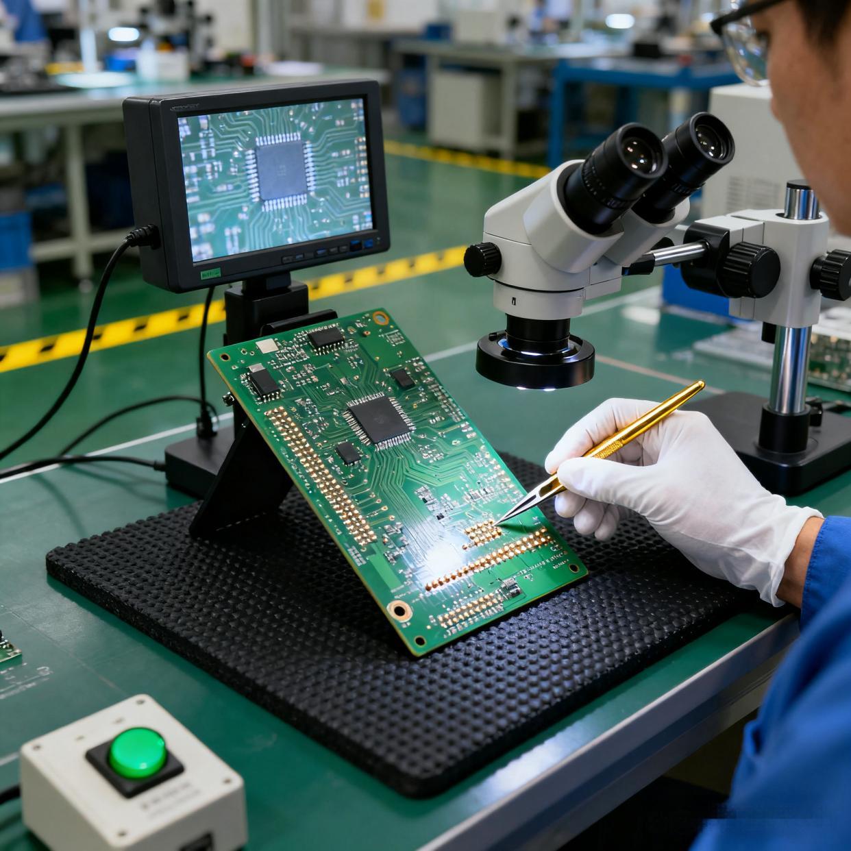
Next, perform a visual inspection. This simple act often reveals more information than expected. Look for burned areas, cracked components, lifted pads, poor solder joints, or debris. A magnifying lamp makes this process easier.
After the visual check, inspect connectors, jumpers, and wires. Loose connections appear harmless but often create intermittent issues that feel impossible to catch. A light touch with tweezers confirms stability.
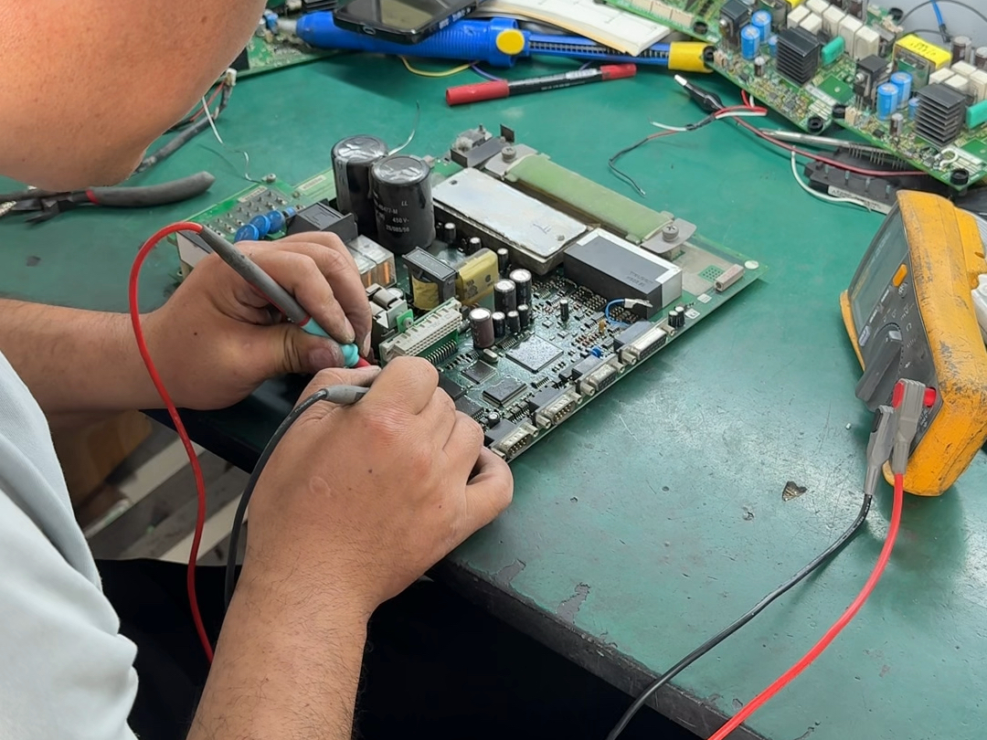
Once the board passes the visual stage, move to electrical testing. A multimeter becomes your most trusted tool. Use continuity mode to confirm that important traces are connected. Use voltage mode to verify that power rails provide stable output. Use resistance mode to track suspicious paths.
During testing. If something feels unusual—temperature differences, unexpected noise, odd smells—pause and investigate.
By following these steps slowly and calmly, you can test an electronic circuit board with clarity and success.
How to Test Electronic Components on a Circuit Board?
Testing individual components is the next logical step because a PCB is only as reliable as each device mounted on it. When a component fails, it often takes down the entire function.
Start with passive components. Resistors are easy to check using the resistance mode on a multimeter. Measure across both ends. If the value appears close to the labeled rating, the resistor is healthy. If the value is extremely high, open, or inconsistent, it may be faulty.
Capacitors require a different approach. When testing capacitors, use capacitance mode if available. For electrolytic capacitors, check for bulging or leaking material. These symptoms almost always indicate failure. For ceramic capacitors, inspect for cracks. Even hairline cracks can cause unstable behavior.
Next, check diodes. These parts allow current to flow in only one direction. Use diode mode on your multimeter. A healthy diode shows one direction with low forward voltage and the other direction with high resistance. If it shows low resistance in both directions, it is bad.
Transistors require a bit more attention. You can test them using diode mode by checking junction behavior. If the readings do not follow expected patterns, the transistor may be damaged.
Integrated circuits are more complex to test directly. Instead, check their input and output voltages relative to the datasheet. If the IC receives the correct signals but responds incorrectly, it may be faulty.
Sensors, connectors, coils, and switches also deserve inspection. Loose contacts or internal breaks lead to intermittent failures that frustrate even experienced technicians.
How to Test Circuit for Short on Electronic Board?
A short circuit is one of the most common and stressful PCB issues. The good news is that detecting a short is often easier than expected, especially when using the right steps.
Begin by switching your multimeter to continuity mode. Touch one probe to the ground reference. Touch the other to various power points such as 3.3 V, 5 V, or 12 V rails. If you hear a beep, it means there is continuity—possibly a short.
Do not panic if continuity appears at first. Some circuits use intentional low-resistance paths. Instead, look for extremely low resistance, usually near zero ohms. That value often indicates a short.
Move through the board section by section. Check areas where power lines run close to ground. Solder bridges, damaged vias, and misaligned components cause accidental shorts more often than people realize.
If the PCB is multi-layer, you may need to isolate regions by lifting components such as decoupling capacitors. Removing them temporarily helps narrow down the exact node causing trouble.
Thermal cameras, even simple ones, can help detect shockingly fast where the short is hiding. Components sitting on a short path heat up quickly even with tiny amounts of voltage.
How to Test if a Circuit Board Is Bad?
- First, observe the power behavior. If the board fails to start or shows unstable voltage, there may be a damaged regulator or short. Use your multimeter to check the rails. Healthy boards deliver stable readings.
- Second, examine functionality. Does the board complete its tasks? Do LEDs light as expected? Does the CPU start? Even small symptoms provide big clues. For instance, an LED flickering instead of glowing steadily indicates unstable current or improper grounding.
- Next, perform thermal observation. If any component heats too quickly, it may be failing. Healthy boards warm slowly and evenly.
- Another sign is physical condition. Bad boards often exhibit damaged traces, cracked solder joints, corrosion, or burnt areas.
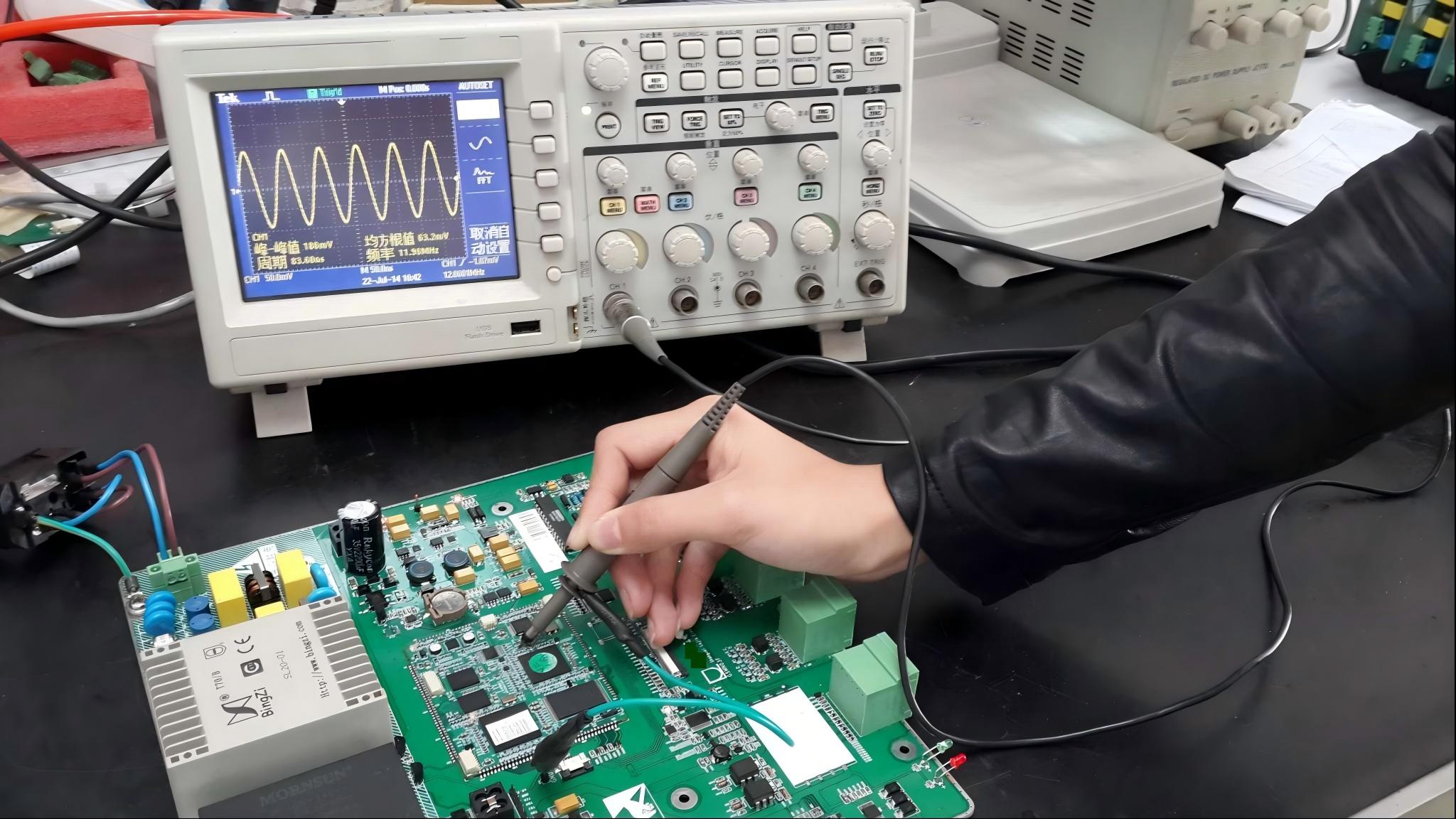
Software tools such as oscilloscopes or logic analyzers can also reveal deeper issues. Incorrect waveforms often indicate a bad board even when the components appear intact.
If several tests reveal inconsistent results, or if the board repeatedly fails under mild load, it is likely defective.
How Do I Test a PCB with a Multimeter?
A multimeter is one of the most powerful tools for testing PCBs because it reveals real electrical behavior.
To begin, ensure the multimeter battery is healthy. Weak multimeter power may give misleading readings.
Use the continuity mode to trace connections. This test is simple but effective because it verifies whether the PCB’s paths are intact. Place one probe on one end of a trace and the second at the opposite end. If the multimeter beeps, you confirm electrical continuity.
Use the resistance mode to examine suspicious components. High resistance where there should be low resistance is a warning.
Then use voltage mode on a powered board. Measure power rails to confirm stable output. Move on to test key IC pins. Compare the readings with datasheet requirements. Small deviations may indicate early failures. Larger gaps point to serious issues.
Finally, use current measurement if necessary. This test should be done carefully. Excess current flow usually points to a short or overheating component.
Can You Cut a Circuit Board and It Still Work?
The answer is: yes, a circuit board can still work after cutting, but only under specific conditions.
Cutting a PCB should be done with extreme care. The board will continue working only if you avoid damaging active traces, copper planes, or functional zones. Many PCBs contain dense routing, so a careless cut could destroy the device.
If you must cut a circuit board, examine the board layout first. Look for areas without copper. Many boards intentionally include cut-lines for modular use. These areas are safe to cut as long as you stay within the boundaries.
Use tools designed for PCB cutting such as scoring knives, mills, or board shears. Regular tools may crack the laminate or tear pads.
After cutting, inspect the edges. Smooth them if needed. Ensure no copper is exposed or touching unwanted surfaces.
When done properly, a cut PCB can continue working exactly as before. It depends entirely on how well you prepare and execute the cut.
How to Troubleshoot and Repair Electronic Circuit Boards?
Troubleshooting a PCB is a blend of logic, patience, and methodical thinking. The process begins with clear observation and continues through structured testing until the root problem is solved.
- Start with the symptom list. What exactly is the board failing to do?
- Next, examine power. In many cases, weak or unstable power is the hidden cause behind strange behavior.
- Move on to signal behavior. Use tools like oscilloscopes or logic probes to check timing and waveform integrity. Unexpected waveforms often signal failing components or broken connections.
- Then follow a zone-based approach. Break the board into functional regions—power, processing, communication, outputs, and sensors. If you suspect a component, replace one part at a time. Do not replace everything at once.
- Reflowing solder joints also saves many boards. Cold joints and cracked pads create intermittent issues that vanish after a clean reflow.
With these methods, troubleshooting and repairing electronic circuit boards will become a predictable process.
Conclusion:
Whether you are checking components, detecting shorts, verifying power rails, testing the board with a multimeter, cutting a PCB safely, or repairing complex circuits, the process becomes manageable when broken into structured steps.
If you need assistance with PCB design, manufacturing, or troubleshooting support, feel free to contact us at sales@bestpcbs.com