

MCX Connector PCB is a critical high-frequency interconnect solution that mounts Miniature Coaxial (MCX) connectors directly onto printed circuit boards, enabling reliable RF signal transmission in compact electronic assemblies. This comprehensive guide explores the design, selection, application, and manufacturing of MCX connector PCBs, with a focus on the complete turnkey process from initial design to final assembly.
For engineers sourcing MCX connector PCBs, the path from concept to a fully functional, mass-produced RF board is fraught with challenges. What are the most common pain points developers face when integrating these specialized components?
- Signal Degradation and Mismatch: Improper impedance control or layout around the MCX PCB connector footprint causes significant RF signal loss, return loss, and degraded system performance.
- Mechanical Failure in the Field: Choosing a connector with inadequate locking mechanism or PCB retention can lead to intermittent connections or the MCX connector detaching from the PCB under vibration.
- Prototyping Bottlenecks: Difficulty in obtaining small-batch, reliable prototypes for testing from suppliers who only focus on high-volume orders, stalling the design verification phase.
- Inconsistent Quality in Volume: Receiving production batches with poor soldering, misaligned connectors, or inconsistent plating that fails during assembly or compliance testing.
- Hidden Costs and Timeline Delays: Unexpected expenses and delays arise from dealing with multiple vendors for design, PCB fabrication, connector sourcing, and assembly, coupled with poor communication.
Here is how a full-turnkey service model directly addresses these critical issues.
- Expert RF Design Review: A specialized manufacturer provides upfront Design for Manufacturability (DFM) and Design for Excellence (DFX) analysis specifically for RF layouts, ensuring optimal impedance matching and placement to eliminate signal integrity issues from the start.
- Validated Component Sourcing: Leveraging direct relationships with trusted connector manufacturers (like those producing China MCX connector PCB components) to supply genuine, mechanically robust connectors with verified specifications for reliable mating and board retention.
- Rapid Prototyping Services: Offering fast-turn, low-volume prototype builds that use the same processes as mass production, allowing for real-world performance validation without delaying the project timeline.
- Integrated High-Precision Manufacturing: Controlling the entire production line—from PCB fabrication with tight impedance tolerance to automated, optical-inspected assembly—ensures consistent, high-quality output in every batch, whether for prototypes or volume runs.
- Unified Project Management: A single point of contact and responsibility for the entire full turnkey process—from initial design files to final assembled and tested boards—eliminates vendor coordination hassles, provides cost transparency, and guarantees on-time delivery.
At BEST Technology, we specialize in providing exactly this seamless, end-to-end service. As a professional MCX connector PCB factory, we combine deep RF expertise with advanced manufacturing capabilities to deliver reliable, high-performance boards. From selecting the right PCB MCX male connector to ensuring flawless assembly, we manage every detail, allowing you to focus on your core product development. Pls feel free to contact our team at sales@bestpcbs.com to transform your RF board requirements into a perfected product.
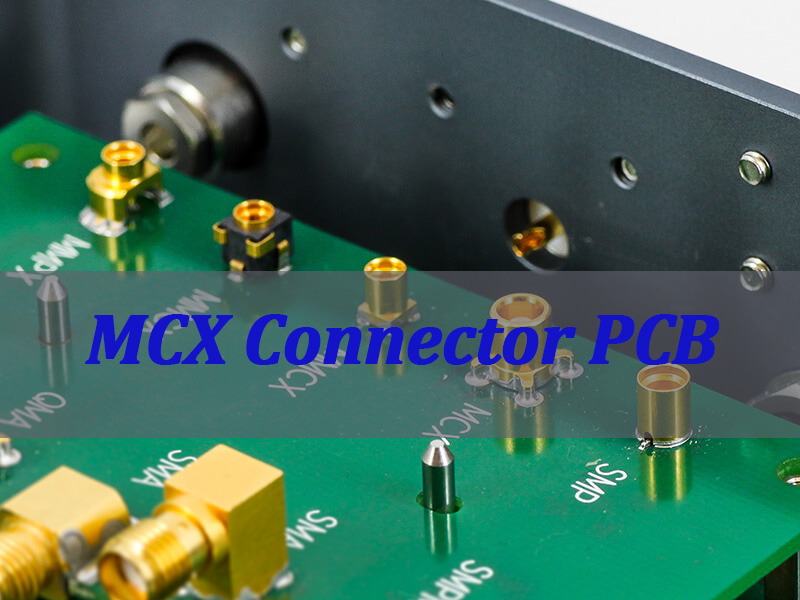
What Is an MCX Connector PCB?
An MCX Connector PCB refers to a printed circuit board that incorporates Miniature Coaxial (MCX) connectors as integrated board-mount interfaces. These connectors are known for their compact size, snap-on coupling mechanism, and excellent performance through several GHz, making them ideal for space-constrained RF applications.
- Core Components: The system consists of the PCB itself (with controlled-impedance traces), the connector’s solderable footprint, and the MCX PCB connector (male or female) which is soldered onto the board.
- Key Interface: It serves as the critical transition point between the controlled environment of the PCB trace and the external coaxial cable, minimizing signal reflection and loss.
- Common Formats: Boards can feature various layouts, including edge-mounted connectors, through-hole designs, or MCX jack panel PCB connector arrays for chassis interfaces.
In essence, an MCX Connector PCB is a fundamental building block in modern RF systems, enabling efficient and reliable high-frequency signal ingress and egress in a miniaturized format. Choosing a reliable pcb mcx jack connector factory is crucial for ensuring the performance of this critical link.
Where Is MCX Connector PCB Commonly Used in RF Systems?
MCX connector PCBs are ubiquitous in applications where a blend of small form factor, reliable RF performance, and moderate frequency requirements converge. Their usage spans commercial, consumer, and industrial sectors.
| Application Sector | Specific Use Cases | Why MCX is Preferred |
|---|---|---|
| Telecommunications | Cellular repeaters, base station subsystems, GSM MCX PCB connector modules, antenna feeder links. | Compact size, good performance at cellular bands (e.g., 900 MHz, 1800 MHz). |
| IoT & Wireless Devices | Wireless sensors, RFID readers, LPWAN gateways, short-range communication modules (Bluetooth, Zigbee). | Saves valuable board space in compact devices. |
| Test & Measurement | Portable analyzers, signal generator modules, internal interconnects in lab equipment. | Allows for dense connector arrangements on panels. |
| Broadcast & AV | Digital video broadcast (DVB) equipment, satellite receiver LNBs, in-car entertainment systems. | Reliable performance for video/audio signal transmission. |
| Aerospace & Defense | Avionics comms, UAV telemetry, GPS modules, and other space-constrained onboard systems. | Lightweight and secure snap-on mating withstands mild vibration. |
From enabling the GSM backhaul in remote locations to connecting antennas on a compact IoT sensor, the MCX connector PCB is a versatile workhorse. The trend towards miniaturization continues to drive its adoption, making a partner like a proficient China PCB MCX male connector supplier essential for developers worldwide.
Key Structural Differences Between MCX PCB Connectors and Other RF PCB Mount Connectors
Selecting the right RF connector involves understanding mechanical and electrical trade-offs. MCX, SMA, and SMP are common choices, each with distinct structural advantages.
- 1. Coupling Mechanism:
- MCX: Uses a snap-on, quick-connect/disconnect interface. It mates with a simple push and releases with a gentle pull, offering speed but a relatively lower mating security compared to threaded types.
- SMA: Features a robust threaded coupling mechanism. It provides very high mechanical stability and superior shielding but requires more time and space for wrench tightening.
- SMP (SubMiniature Push-on): Offers a slide-on/push-off action with a distinct detent. It provides a good compromise between MCX’s speed and SMA’s security, often used for blind-mate applications.
- 2. Size and Weight:
- MCX: Has the smallest outer diameter (~3.5mm) and is very lightweight, enabling the highest port density on a panel PCB connector.
- SMA: Significantly larger and heavier (~5mm+ diameter), reducing the number of connectors that can be placed in a given area.
- SMP: Slightly larger than MCX but smaller than SMA, offering a dense yet more secure alternative.
- 3. Frequency Performance:
- MCX: Typically rated for reliable operation up to 6 GHz, suitable for many commercial wireless applications.
- SMA: A true workhorse, often specified for performance up to 18 GHz or even 26.5 GHz in precision versions.
- SMP: Can perform into the millimeter-wave range, with many variants rated for 40 GHz and beyond.
- 4. Mechanical Durability:
- MCX: Rated for around 500 mating cycles. Its plastic snap-ring is the wear point, making it suitable for applications not requiring frequent connection changes.
- SMA: Can withstand 500+ mating cycles (with metal-on-metal threading), ideal for test equipment and field-deployed gear.
- SMP: Mating cycle life varies by design but generally falls between MCX and SMA.
In summary, the MCX PCB connector is the choice for ultimate miniaturization and quick connection where extreme mechanical robustness or ultra-high frequency is not the primary driver. Its structure defines its niche in the RF interconnect ecosystem.
How to Select the Right MCX PCB Connector for Signal Integrity and Mechanical Stability?
Choosing the optimal MCX connector is a balancing act between electrical performance and physical reliability. Key factors must be evaluated against your specific application requirements.
- 1. Impedance Matching: The connector must be 50Ω (standard for RF) to match your controlled-impedance PCB trace. Any mismatch creates signal reflections (high VSWR). Verify the connector’s datasheet impedance specification.
- 2. Frequency Range & VSWR: Check the connector’s rated maximum frequency and its Voltage Standing Wave Ratio (VSWR) performance across your band of operation. A lower, flatter VSWR (e.g., <1.3:1) indicates better signal integrity.
- 3. Interface Gender and Configuration: Decide between a PCB MCX male connector (pin) or a female (socket) for board-mount. Consider if you need a straight, right-angle, or edge-mount type based on your board layout and cable routing.
- 4. Termination and Retention: Evaluate the PCB tail style (surface-mount/SMT or through-hole) and the board retention features. SMT saves space, but through-hole provides stronger mechanical bonding. Look for connectors with solder tabs or mounting ears for enhanced stability, especially for the PCB mount female MCX switch connector types that may see actuation force.
- 5. Material and Plating: The center contact is typically beryllium copper for spring properties, plated with gold over nickel for low resistance and corrosion resistance. The outer body/collet should be brass or similar, with a corrosion-resistant finish. Inferior plating increases insertion loss and degrades over time.
- 6. Mating and Unmating Force: Ensure the connector’s specified mating force aligns with your assembly process and end-use. Too high a force can damage the board; too low can lead to unreliable connections.
By systematically analyzing these factors against your operational environment (temperature, vibration, mating cycles) and signal requirements, you can select an MCX PCB connector that ensures both a clean signal path and long-term reliability on the board.
Design Considerations When Integrating GSM MCX PCB Connector Into RF and IoT Boards
A GSM MCX PCB Connector is a specific type of MCX connector PCB interface designed and optimized for use in GSM (Global System for Mobile Communications) frequency bands, primarily 850/900 MHz and 1800/1900 MHz. It is selected for its compact size and adequate performance within these cellular ranges, commonly found in modules, repeaters, and IoT devices with cellular connectivity.
Integrating a GSM MCX PCB connector successfully requires attention to both RF principles and practical layout constraints to ensure the module performs as intended in the final product.
- 1. Impedance Continuity is Paramount: The 50-ohm microstrip or coplanar waveguide trace leading to the connector must be designed with precise width and spacing, considering the PCB stack-up. The transition from the trace to the connector pad must be as smooth as possible to minimize discontinuities. Use simulation tools if available.
- 2. Grounding and Via Fencing: Provide an excellent, low-inductance RF ground for the connector. This involves:
- Placing a dense array of grounding vias (a “via fence”) immediately around the connector’s ground pads.
- Ensuring ground pours on multiple layers are stitched together with vias to form a solid ground cage, preventing parasitic modes.
- 3. Keep-Out and Component Placement: Maintain a clear keep-out area around the connector footprint, especially in the direction of the mating interface. Do not place tall components nearby that could obstruct cable attachment. Keep sensitive analog or high-speed digital traces away from the RF path to avoid coupling.
- 4. Mechanical Reinforcement: For applications subject to vibration or where the cable may be stressed, consider adding mechanical support. This can include:
- Using through-hole connector variants for stronger bond.
- Adding epoxy strain relief spots on the connector body after soldering (often done in assembly).
- Designing a board cut-out or chassis support to take lateral force off the solder joints.
- 5. DFM/DFA for Assembly: Design the footprint according to the connector manufacturer’s recommended land pattern. Ensure solder paste stencil apertures are correctly sized to prevent tombstoning (for SMT types) or solder voids. Clear silkscreen markings for orientation aid assembly technicians.
In practice, a well-integrated GSM MCX PCB connector should appear electrically “invisible” at its operating frequency, providing a seamless, low-loss transition between the board and the antenna system. Neglecting these considerations can lead to reduced range, dropped connections, and failed compliance tests.
Manufacturing Capabilities of a Reliable MCX Connector PCB Factory for Volume Production
A factory capable of delivering high-volume, reliable MCX connector PCBs must possess a tightly integrated set of capabilities that span materials, precision fabrication, and automated assembly. This is what separates a true turnkey partner from a simple board fab house.
- Advanced PCB Fabrication: Expertise in producing boards with tightly controlled dielectric constants (Dk) and loss tangents, and impedance control with tolerances of ±5% or better. This includes mastery of materials like FR-4, Rogers, or hybrid stacks.
- Automated, High-Precision Assembly: Utilizing chip shooter and fine-pitch placement machines for accurate SMT component placement, coupled with advanced solder paste inspection (SPI) and reflow profiling to ensure perfect soldering of the tiny MCX PCB connector leads.
- Stringent Quality Control Regime: Implementing a multi-stage inspection protocol including Automated Optical Inspection (AOI) for solder joint quality, X-ray inspection for hidden voids (especially on BGA or under connectors), and 100% electrical testing of the RF path for continuity and shorts.
- Supply Chain Mastery: Established, vetted relationships with top-tier connector manufacturers to ensure a steady supply of authentic, high-performance MCX PCB connectors, avoiding counterfeit or substandard components that plague the market.
- Scalable Process Engineering: The ability to seamlessly scale from a few prototype boards to thousands of production units while maintaining consistent quality. This involves process optimization, fixture design for panelization, and efficient throughput.
A reliable MCX connector PCB factory like BEST Technology combines these capabilities under one roof. This vertical integration and control over the entire process—from sourcing the right China MCX connector to final RF testing—is what guarantees a manufacturable design and a flawless, on-schedule production run for our clients.
What Determines the Cost Structure in an MCX Connector PCB Pricelist?
Understanding the MCX connector PCB pricelist requires breaking down the cost drivers at each stage of the turnkey process. Transparency here helps in budgeting and value engineering.
| Cost Driver Category | Specific Factors | Impact on Final Cost |
|---|---|---|
| PCB Fabrication | Board material (FR-4 vs. RF laminate), layer count, board size/panel utilization, impedance control tolerance, surface finish (ENIG), and special requirements (like blind vias). | This forms the base substrate cost. High-frequency materials and tight tolerances increase cost. |
| Component Cost | The unit price of the MCX PCB connectors themselves, which varies by brand, plating quality, and configuration (e.g., right-angle vs. straight). Switches or other special components also add cost. | A significant portion of the BOM cost, especially for high-quality, brand-name connectors. |
| Assembly Complexity | Number of components, mix of technology (SMT vs. thru-hole), density, and need for special processes (e.g., underfill, selective soldering for a PCB mount female MCX switch connector). | Higher complexity requires more sophisticated equipment and time, increasing labor and machine costs. |
| Testing & Qualification | Level of testing required: basic continuity, full functional test, or RF parameter verification (VSWR, insertion loss). Fixture development costs for automated testing. | More comprehensive testing adds upfront engineering and per-unit time costs but reduces field failure risk. |
| Order Volume & Logistics | Economies of scale: unit cost drops significantly with higher volumes. Packaging requirements and shipping destination also factor in. | Prototypes are inherently higher cost per unit. Large volumes spread fixed costs (setup, tooling) over more units. |
When reviewing a pricelist, it’s crucial to look beyond the simple per-board quote. The value lies in a supplier’s ability to optimize these factors—through smart material selection, efficient panel design, and bulk purchasing—to deliver the required performance at the best total cost of ownership. Requesting a detailed breakdown from your MCX connector PCB factory is always a best practice.
Application Scenarios for PCB Mount Female MCX Switch Connector in Compact RF Devices
The PCB mount female MCX switch connector is a specialized variant that integrates a switching function—typically between an internal antenna path and an external port—directly onto the board. This component is invaluable for adding flexibility and testability to space-constrained designs.
- 1. Internal/External Antenna Selection: The most common use. The switch allows the RF transceiver to connect to either a small, integrated PCB antenna or an external, high-gain antenna via the MCX port. This is crucial for devices that may be used in varying signal strength environments.
- 2. Production Line Testing and Calibration: The switch connector provides a dedicated, easily accessible test point. During manufacturing, test equipment can be connected to calibrate output power, frequency, and modulation accuracy without interfering with the operational antenna, speeding up the testing process.
- 3. Field Diagnostics and Maintenance: For deployed equipment, a technician can connect a portable analyzer to the external port to diagnose signal issues without opening the device casing, enabling quick troubleshooting and minimal downtime.
- 4. Signal Path Bypass or Loopback: In some designs, the switch can be used to create a controlled loopback path from the transmitter to the receiver for self-test or diagnostic routines, improving system reliability.
- 5. Multi-mode Device Configuration: In devices that support multiple communication standards (e.g., Cellular + GPS), a switch can be used to route signals from different internal modules to a common external antenna connector, simplifying the mechanical design.
By integrating this functionality, the PCB mount female MCX switch connector saves significant board space compared to using a separate RF switch IC and connector. It simplifies the RF front-end layout, reduces component count, and enhances the device’s field utility, making it a strategic component in sophisticated compact devices. Partnering with an expert PCB MCX male connector factory that understands these applications ensures you get a component that meets both electrical and mechanical lifecycle requirements.
Why Engineers Purchase China MCX Connector PCB from EBest Circuit (Best Technology)?
Engineers and procurement specialists globally turn to BEST Technology for their China MCX Connector PCB needs because we solve the core dilemma: achieving high-performance, reliable RF boards at a scalable cost without compromising on service or technical expertise. We are not just a supplier; we are a full-turnkey engineering and manufacturing partner.
- End-to-End Ownership: We manage the entire process—from design review and PCB MCX connector sourcing to fabrication, assembly, and testing. This single-point accountability eliminates finger-pointing between vendors and ensures seamless project execution.
- Deep RF & Manufacturing Expertise: Our engineering team possesses specialized knowledge in RF layout and DFM. We proactively identify and resolve potential signal integrity or manufacturability issues before they become costly prototypes or production delays.
- Uncompromising Quality with Cost Efficiency: By operating our own advanced manufacturing facilities and leveraging our position in the robust China PCB supply chain, we control quality at every step while optimizing costs. This allows us to offer a compelling MCX connector PCB pricelist without cutting corners on materials or processes.
- Scalability from Prototype to Volume: We support you at every stage. We deliver fast, functional prototypes for validation and seamlessly transition to high-volume manufacturing with consistent quality, ensuring your time-to-market is accelerated.
- Proactive Communication and Support: We assign a dedicated project manager to every order, providing clear, timely updates and acting as your technical liaison. We believe transparent partnership is key to success.
Choosing BEST Technology means investing in a hassle-free pathway from concept to a high-quality, assembled board. We provide the certainty, performance, and partnership that complex RF projects demand.
Overall, MCX Connector PCBs are essential, high-performance interconnects that enable reliable RF signal transitions in increasingly miniaturized and complex electronic devices. This guide has comprehensively covered their definition, application, selection, design, and manufacturing, highlighting the critical importance of a integrated approach from design to assembly.
For projects where performance, reliability, and timeline cannot be left to chance, partnering with an expert full-turnkey provider is the most strategic decision. BEST Technology embodies this partnership, combining deep RF engineering insight with vertically controlled manufacturing to deliver superior MCX Connector PCBs. Let us manage the complexities so you can focus on innovation. A warm welcome to contact our technical sales team at sales@bestpcbs.com for a consultation and quote.