

PCB board colors refer to the solder mask hues applied to printed circuit boards, which not only enhance aesthetics but also serve critical functions like insulation and protection. This article explores the significance, processes, and quality aspects of PCB colors, offering insights for selecting the right options for your projects.
Are you struggling with inconsistent PCB color results or defects that impact performance? Common challenges include color variations, poor adhesion, and reliability issues. Below, we outline five key pain points faced by PCB buyers:
- Inconsistent color coverage leading to uneven appearance.
- Solder mask defects such as scratches or debris affecting functionality.
- Difficulty in achieving precise color matching across batches.
- Inadequate inspections resulting in undetected quality issues.
- Limited process capabilities hindering complex designs.
To address these, BEST Technology provides robust solutions:
- Strict process controls ensure uniform color application.
- Advanced defect prevention techniques minimize errors.
- Custom color matching with high-resolution techniques.
- Comprehensive inspections meet industry standards.
- High-precision manufacturing supports diverse color requirements.
BEST Technology is a professional PCB and PCBA manufacturer with expertise in solder mask applications, leveraging state-of-the-art equipment and stringent quality checks to deliver reliable boards. Pls feel free to contact us at sales@bestpcbs.com for tailored solutions.
What Is the Color of a PCB Board?
The color of a PCB (Printed Circuit Board) board primarily refers to the color of the solder mask, a protective layer applied over the copper traces to prevent short circuits, reduce solder loss, and provide insulation.
Common PCB Colors and Their Features
Green Solder Mask:
- Popularity and Cost:
Green is the most widely used color because it is the cheapest and most readily available.
It offers excellent reliability and is environmentally friendly, as it does not release toxic gases under high temperatures.
- Manufacturing Advantages:
In SMT (Surface Mount Technology) processes, green provides a good contrast for optical alignment during soldering, improving accuracy.
Additionally, it minimizes issues like solder bridging, with a typical solder mask bridge width of 3mil for standard green boards.
- Documentation Support: As noted in the materials, green is considered “common grade” and is less prone to problems such as color variation or handling difficulties compared to other colors.
Other Colors (e.g., Black, Blue, White, Red, Yellow):
Black Solder Mask:
- Often perceived as high-end, black is challenging to manufacture because it absorbs UV light strongly during exposure, requiring a wider solder mask bridge (e.g., 4-6mil) to prevent defects.
- This can lead to design constraints, such as larger pad spacing.
- It is also less ideal for mass production due to higher rejection rates.
Blue Solder Mask:
- Blue is considered novel and aesthetically pleasing but has several drawbacks.
- Blue ink is more expensive (e.g., about 20 RMB/m² more for domestic blue ink than green), and it suffers from issues like lower hardness (making it prone to scratches), poor flow control (leading uneven coating), difficulty in hole plugging, longer baking times, and color changes after SMT.
- These factors increase production costs and defect rates.
White Solder Mask:
- White solder mask is widely used on metal-based PCBs, especially in LED and lighting applications, because of its excellent light reflectivity.
- It enhances brightness and thermal performance by reflecting more light and reducing heat absorption from high-power LEDs.
- Compared with darker solder mask colors, white provides a cleaner appearance and supports better optical efficiency in aluminum‐based and copper‐based board designs.
Red and Yellow Solder Masks:
- Colors like red and yellow are used sparingly, often in niche products like IT devices without enclosures, but they share similar challenges with blue and black, such as variability in batch colors and higher sensitivity to process conditions.
In summary, PCB color choices depend on factors like aesthetics, cost, and application-specific needs. While green remains the recommended color among other colors.
Why Are Circuit Boards Green?
The solder mask, often called “green oil” in the industry, is essential for PCB functionality. While green is the most common color, accounting for over 90% of PCBs due to its cost-effectiveness and reliability, other colors like black, blue, red, white, and yellow are also used for specific applications, such as aesthetics or thermal management.
Green vs. Blue Solder Mask
Price:
- Blue solder mask is more expensive—domestic blue ink costs about 20 RMB/m² more than green, while imported blue ink (e.g., Japanese) can be 100 RMB/m² higher.
- This translates to a cost increase of 0.05–0.30 RMB per unit for products like DVD players.
Performance and Reliability:
- Green ink is harder and more durable, reducing scratches and production defects.
- Blue ink has higher fluidity, causing issues like oil accumulation and uneven coating, which require PCBs to be laid flat during production, occupying more space.
- It also tends to discolor after SMT due to interactions with flux, and batch-to-color variation is common.
Manufacturing Considerations:
- Blue ink requires longer baking times and is more susceptible to contamination, increasing complexity.
- For example, solder mask bridging is harder to achieve with blue—typically needing a width of 3.5mil compared to 3mil for green, which affects design rules (e.g., pad spacing must be at least 7.5mil for blue vs. 7mil for green).
Human Factors:
- Blue can cause more visual fatigue for assembly line workers compared to green, which is gentler on the eyes during prolonged inspections.
In summary, while PCB color choices depend on factors like aesthetics, cost, and application-specific needs, green remains the recommended color for most scenarios due to its cost-effectiveness, ease of manufacturing, and reliability. Other colors, such as blue or black, may suit high-end or specialized products but come with trade-offs in production stability and cost.
When selecting a color, designers should consider manufacturing capabilities, as illustrated in the case where black solder mask required adjustments to pad spacing to ensure solder mask bridges. Ultimately, green solder mask balances performance and economy, making it the industry standard.
What Silkscreen Machines Are Most Commonly Used Across Different PCB Colors?
Silkscreen machines are crucial for applying solder mask evenly. The most common types include:
- Manual screen printers: These machines rely entirely on the operator for controlling the upward and downward movement of the screen frame, along with the pressure and motion of the squeegee. They are suitable for small batches or repair work but depend heavily on operator skill and consistency.
- Semi-automatic screen printers: In these machines, loading and unloading the PCB are handled manually, while the printing stroke is mechanically controlled. Semi-automatic printers are widely used in PCB factories, including those at BEST Technology, because they deliver stable precision with higher efficiency than manual systems.
- Full-automatic screen printers: By equipping a semi-automatic printer with automated feeding and output modules, it becomes a fully automatic screen printer.
These systems support high-volume production, reduce labor dependency, and improve uniformity in solder mask or silkscreen application.
Across different PCB board colors, these machines help maintain consistent printing quality. Parameters such as screen tension, squeegee hardness, printing pressure, and ink viscosity can be fine-tuned to achieve optimal results for each color.
What Inspections Are Required for a Green Color PCB Board?
A green PCB board requires a comprehensive series of quality inspections to ensure its solder mask provides reliable electrical insulation, mechanical protection, and long-term durability.
1. Adhesion Test
- Requirement: 100/100 (Perfect adhesion with no lifting).
- Method: Tested according to the IPC-SM-840B standard. This verifies the solder mask bonds completely to the underlying substrate and copper traces, preventing delamination.
2. Hardness Test
- Requirement: 6H pencil hardness.
- Method: Tested per IPC-SM-840B. This measures the coating’s resistance to scratches and abrasion during handling and assembly.
3. Surface Insulation Resistance (SIR) Test
- Requirement: ≥ 1 x 10¹⁰ Ohms.
- Method: Tested per IPC-SM-840B. This critical electrical test ensures the green solder mask maintains high insulation resistance between conductors, preventing current leakage.
4. Withstand Voltage (Dielectric Withstanding Voltage) Test
- Requirement: 500 VDC per MIL (mil thickness standard).
- Method: Tested per IPC-SM-840B. This verifies the mask can withstand high voltages without breaking down, which is essential for safety and reliability.
5. Solvent & Chemical Resistance Test
- Solvent Resistance: Must withstand immersion for 30 minutes or more at room temperature.
- Chemical Resistance: Must withstand immersion for 60 minutes at room temperature.
- Method: This involves immersion in common solvents and chemicals to ensure the mask does not degrade, blister, or dissolve during cleaning processes.
6. Solderability and Thermal Stress Test
- Requirement: Performance must be “Good” (no blistering, lifting, or cracking).
- Method: The board is subjected to solder float or infrared reflow at 260°C for 15 seconds over 4 cycles. This simulates the thermal shock of assembly and checks the mask’s stability.
7. Thermal Cycle Resistance Test
- Requirement: Performance must be “Good” after extreme cycling.
- Method: The board undergoes 200 cycles of thermal shock, alternating between 260°C for 5 seconds and -1°C for 20 seconds. This evaluates the mask’s ability to withstand expansion and contraction without failure.
8. Flammability Rating
- Requirement: Must achieve a rating of “Good,” typically corresponding to the UL94 V-0 standard.
- Method: Tested to the UL94V-0 protocol. This is a safety requirement to ensure the solder mask material is self-extinguishing and meets fire safety regulations.
9. Solder Mask Thickness Measurement
- Requirement: Based on customer specifications. A common general requirement is a minimum of 0.4 mils (≈10 μm) over traces and 0.8 mils (≈20 μm) over the base laminate.
- Method: Verified via micro-sectioning (cross-section analysis). This ensures the coating is sufficiently thick to provide insulation but not so thick as to cause other manufacturing issues.
In summary, a green color PCB board must pass a rigorous battery of inspections covering mechanical adhesion, electrical insulation, environmental resistance, and thermal reliability. These tests, standardized under protocols like IPC-SM-840B, are not merely procedural but are fundamental to guaranteeing that the board will perform reliably in its final application. While the green solder mask is renowned for its cost-effectiveness and ease of manufacturing, this reputation is underpinned by these stringent quality controls that ensure consistency and durability.
What Process Capabilities Can Be Achieved Across Different PCB Board Colors?
Process capabilities for PCB board colors include precision and thickness control.
- Alignment accuracy: ±0.05mm for precise color registration.
- Solder mask thickness: Minimum 10μm, ensuring adequate coverage.
- Bridge width: As narrow as 0.07mm for fine patterns.
- Via plugging: Handling apertures from 0.25mm to 0.6mm.
- Board thickness range: 0.4-4.0mm, accommodating various applications.
These capabilities allow for high-quality results across basic PCB board colors, from green to black or white.
What Solder Mask Quality Defects Are Most Likely to Occur on Various PCB Board Colors?
Common defects in solder mask application, as highlighted in the training material, include scratches, debris under solder mask, thin coating, misalignment and oil pooling.
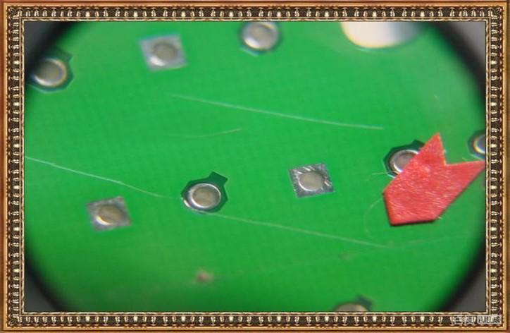
Scratches
Possible Causes
- Operator handling: Scratches may occur during manual operation or rework, especially when dealing with large panels or thin boards that are more prone to surface damage.
- Issues from previous processes: Defects such as surface abrasion, poor touch-up work, or improper cleaning in earlier stages can lead to scratches appearing after solder mask application.
Improvement Actions
- Standardize operator handling: Strengthen training and enforce proper handling procedures to reduce mechanical damage during processing or rework.
- Collect and analyze scrap data: Track defective boards, identify recurring sources, and drive corrective actions in upstream processes.
Debris Under Solder Mask
Possible Causes
- Insufficient cleanliness in the cleanroom: Dust or airborne particles can settle on the panel surface before solder mask coating.
- Copper particles: Residual copper chips from drilling or routing may remain on the board if cleaning is inadequate.
- Contamination at the oven air inlet: Foreign particles entering through the oven’s intake can fall onto the panel during curing.
Improvement Actions
- Maintain cleanroom cleanliness: Strengthen environmental control and regularly monitor airborne particle levels.
- Standardize operator handling: Ensure proper cleaning and handling procedures to prevent debris from being transferred onto the panel.
- Use mesh filters for critical products: For boards with stricter requirements, apply fine mesh filters at the oven air inlet to block contaminants during heating.

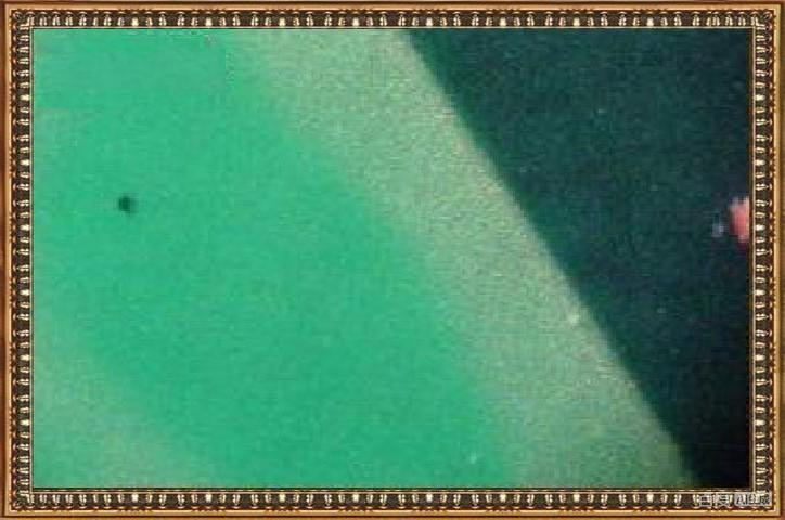
Thin Coating
Possible Causes
- Insufficient ink release from the screen mesh: The mesh may be clogged or contaminated, preventing proper solder mask deposition.
- Panel collision or impact: Boards that bump into each other or equipment may experience uneven or reduced coating thickness.
- Operator-related contamination: Improper handling or unclean garments (cleanroom suits) may interfere with uniform coating.
Improvement Actions
- Clean the screen before mounting and perform paper testing: Ensure the screen is free of residue and conduct test strokes both before and during production to confirm smooth ink flow.
- Follow proper rack spacing: Place panels in every other slot of the rack, and avoid using the outermost slots to prevent collision-related coating issues.
- Ensure proper garment use and careful handling: Operators must wear cleanroom attire correctly and handle boards cautiously to avoid contact that could thin the coating.

Misalignment
Possible Causes
- Print offset: Inaccurate screen positioning or uneven mesh tension can cause the printed solder mask pattern to shift.
- Registration deviation: Misalignment between the solder mask layer and the copper features may occur during exposure or printing.
- Film deformation: The phototool (film) may warp due to humidity, temperature, or aging.
- Film scratches: Damaged or scratched film can lead to distorted alignment marks or incomplete image transfer.
Improvement Actions
- Rework the affected panels: Remove the defective solder mask layer and repeat the process where possible.
- Standardize operator procedures: Enhance training to ensure consistent setup, alignment, and handling.
- Remake the film: Replace any deformed, aged, or damaged phototools to ensure accurate image registration.
- Clean and inspect the film regularly: Clean the film before each exposure and inspect it every 30 panels to ensure surface integrity and alignment accuracy.

Oil Pooling
Possible Causes
- Damaged aluminum stencil or plate: A leak or deformation in the aluminum sheet can cause excess solder mask to flow into undesired areas.
- Improper screen printing parameters: Incorrect squeegee pressure, printing speed, or mesh tension may lead to uneven ink deposition and pooling.
Improvement Actions
- Replace the damaged aluminum plate: Ensure the stencil or support plate is intact to prevent leakage or uncontrolled ink flow.
- Adjust printing parameters: Fine-tune squeegee pressure, speed, and mesh tension to achieve uniform solder mask distribution and avoid pooling.
These defects can occur on any PCB board color change, emphasizing the need for careful process control.
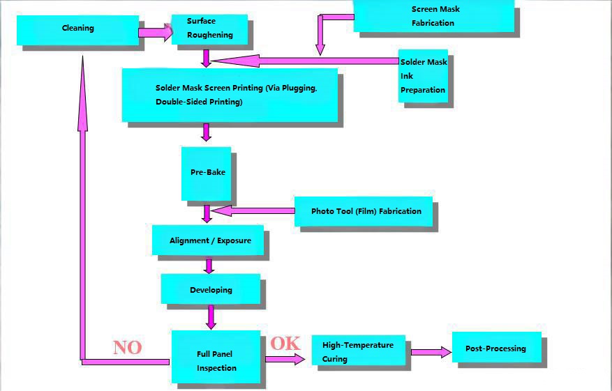
How to Color PCB Board?
Coloring a PCB board is achieved through the solder mask application process, which determines the final PCB board colors used in products ranging from standard electronics to a color TV PCB board. The full process includes ink preparation, surface treatment, coating, imaging, and curing.
Ink Mixing
- The solder mask ink is first prepared by manually premixing the main resin and hardener, followed by mechanical agitation to ensure complete uniformity. The mixed ink is then left to rest for about 15 minutes to eliminate trapped air bubbles before use.
Surface Preparation
- The PCB surface is thoroughly cleaned to remove oxidation, oils, and contaminants. The copper foil is micro-etched or roughened to improve adhesion between the solder mask and the board surface.
Solder Mask Application
- The solder mask is applied using screen printing, allowing the ink to be deposited evenly onto the PCB according to customer specifications. This step determines the consistency and appearance of the final PCB board colors.
Pre-Baking (Tack Drying)
- The printed solder mask is subjected to low-temperature drying to evaporate solvents and partially harden the coating in preparation for UV exposure.
Exposure
- A custom photomask is placed over the PCB, and the panel is exposed to UV light. Areas blocked by the film will not harden and will later be removed, leaving copper pads exposed. The UV-exposed areas harden and bond firmly to the surface.
Development
Unexposed solder mask is washed away, revealing copper pads or openings exactly as required by the design. After development, the PCB surface will fully match the customer’s specifications—areas meant to be covered are coated, and areas requiring exposed copper are cleanly opened.
High-Temperature Curing
- The solder mask undergoes final thermal curing, forming a stable cross-linked network that delivers the required electrical, chemical, and mechanical performance. This final step ensures vibrant, durable, and reliable PCB board colors suitable for a wide range of applications.
This process ensures vibrant and durable PCB board colors, whether for a color TV PCB board or other applications.
Case Studies: How EBest Circuit (Best Technology) Applies PCB Board Colors Expertise in Real Customer Projects
Industrial Control Product with Green PCB Board
This green PCB board is used in industrial automation systems, motor controllers, and power management units, where reliability and visibility are key. The green color provides excellent contrast for maintenance.
- Layers: 6L
- Material: FR4
- Tg: 150
- Copper thickness: 1oz inner and outer
- Board thickness: 1.6mm ±10%
- Solder mask: Green with white legend
- Surface finish: ENIG (Au 1μm)
High-End Consumer Electronics with Black PCB
Black PCBs are ideal for smartphones, gaming consoles, and premium audio devices, offering a sleek appearance and reduced light reflection.
- Layers: 4L
- Material: FR4
- Board thickness: 1.6mm
- Copper: 1oz inner and outer
- Solder mask: Black with white legend
- Additional: Panelized with mark points
Lighting and Medical Equipment with White PCB
White PCBs are used in LED lighting and medical devices like diagnostic tools, providing high reflectivity and cleanliness.
- Structure: Single-sided double-layer copper substrate
- Base thickness: 1.60mm
- Copper thickness: 2oz
- Final thickness: 2.0mm ±10%
- Adhesive: 8W film, 75μm
- Solder mask: White with black legend
- Finish: Ni-Pd-Au 2μm both sides
- Features: Countersunk holes, filled vias
- Documentation: Includes slice and test reports
These cases demonstrate BEST Technology’s ability to handle diverse PCB board colors for full PCBA services.
Why Choose EBest Circuit (Best Technology) for Any PCB Board Colors PCB and PCBA Needs?
Choosing the right PCB and PCBA partner is essential—especially when your design depends on specific PCB board colors for performance, aesthetics, or branding. EBest Circuit (Best Technology) combines strong engineering capability, stable manufacturing systems, and deep expertise in solder mask behavior to support every color requirement with confidence.
1. Proven Expertise Across All PCB Board Colors
We understand the unique production challenges of each solder mask color—from standard green to black, blue, white, and red—and optimize our process accordingly.
- Ink Behavior Control: Fine-tuned viscosity, tension, and squeegee parameters prevent issues like ink accumulation or uneven coating.
- Calibrated Exposure: UV settings adjusted for each color (e.g., higher energy for black) ensure complete and accurate curing.
- Reliable Development: Automated lines maintain consistent pressure and temperature to avoid residual mask or over-development.
- High AOI Accuracy: AOI systems are optimized for color contrast, ensuring stable defect detection.
This ensures consistent, high-quality results no matter which PCB board colors your product requires.
2. Advanced PCB Manufacturing Capability
Our facilities support both simple and highly complex PCB designs:
- 1–40 layer fabrication
- FR4, Rogers, hybrid materials, metal-core substrates
- HDI, blind/buried vias, laser drilling, high-speed/high-frequency builds
- Thick copper options for power electronics
Whether you need white solder mask for LED boards or black solder mask for premium consumer devices, we deliver stable and repeatable quality.
3. Dual Production Base in China and Vietnam
We provide flexible production options tailored to global customer needs:
- Vietnam SMT Factory: Ideal for US/EU clients avoiding tariffs and looking for fast, cost-effective volume production.
- China PCB and SMT Factory: Advanced automation suited for complex, high-mix products and precision assembly.
This dual-site strategy strengthens your supply chain and reduces risk.
4. International Certifications and Quality Systems
We meet global standards required for demanding industries:
- ISO9001, ISO13485, IATF16949, AS9100D
- UL, RoHS, REACH compliance
- Full MES traceability
These systems ensure every PCB board color—and every finished assembly—meets strict reliability requirements.
5. One-Stop PCB & PCBA Services
From prototypes to mass production, we cover the entire process:
- PCB fabrication
- SMT, DIP, wave soldering
- 0201 to BGA, embedded components, coaxial connectors
- AOI, X-Ray, ICT, functional testing
Having fabrication and assembly under one roof reduces communication gaps and accelerates delivery.
6. DFM/DFX Support Tailored to Color-Specific Needs
Our engineering team reviews your design for:
- AOI recognition challenges caused by certain colors
- Solder mask thickness and bridge clearance
- Silkscreen visibility and contrast
Early feedback prevents re-spins, delays, and unexpected costs.
7. Fast, Professional Customer Support
- 24–48 hour engineering feedback
- Quick quotation
- Dedicated English-speaking project managers
- Global shipping with reliable logistics partners
EBest Circuit (Best Technology) keeps your project moving smoothly from start to finish.
In summary, PCB board colors play a vital role in PCB functionality and aesthetics, influencing everything from basic insulation to high-end applications. This article has covered key aspects, from selection to quality control. Pls feel free to reach out for your PCB needs at sales@bestpcbs.com. EBest Circuit (Best Technology) delivers the manufacturing expertise, quality systems, and engineering support needed to handle any PCB board color—green for stability, black for premium aesthetics, white for reflectivity, and more. With dependable production in China and Vietnam, we ensure your products achieve the performance and visual impact you expect.