

Circuit board stencil — also called a PCB stencil or SMT stencil—is a thin sheet with laser-cut openings that align with the solder pads on a printed circuit board. During surface-mount assembly, solder paste is swept across the stencil so precise, repeatable amounts are deposited only where components will be placed.
What Is a Stencil Mask in PCB?
Stencil mask in PCB assembly is a thin sheet with precisely cut openings that match the solder pad layout of the board. During SMT production, solder paste is applied through these openings onto the pads before component placement.
Stencil circuit board defines where solder paste goes and, just as importantly, where it does not. Without a stencil, paste deposition would rely on manual methods or uncontrolled dispensing.
Printed circuit board stencils are used in nearly all automated SMT lines because they support repeatability. Once aligned, the same stencil can be used for hundreds or thousands of print cycles with minimal variation.
In manufacturing environments like EBest Circuit (Best Technology), stencil data is reviewed together with Gerber files during DFM checks. This coordination ensures the stencil design supports the real assembly conditions rather than simply matching the PCB layout on paper.
What Material Is Used for PCB Stencils?
The most common PCB stencil material is stainless steel, chosen for its durability, flatness, and resistance to corrosion. Stainless steel stencils can maintain sharp aperture edges over many print cycles, which helps deliver consistent solder paste release.
Within stainless steel options, there are two main surface conditions. Standard stainless steel offers reliable performance for general applications. Polished or nano-coated steel improves paste release, especially for small apertures and fine-pitch components.
Nickel stencils provide smoother walls and are sometimes used for ultra-fine features. Polymer or Mylar stencils are used mainly for low-volume prototyping, where cost and speed matter more than longevity.
From a production standpoint, stainless steel remains the default choice for professional assembly. At EBest Circuit (Best Technology), stainless steel stencils are standard for customer projects because they balance print quality, lifespan, and cost efficiency across both prototype and mass production runs.
What Are the Different Types of Stencils?
Circuit board stencils can be classified by structure and usage method. Each type serves a specific production scenario.
Common stencil types include:
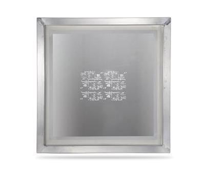
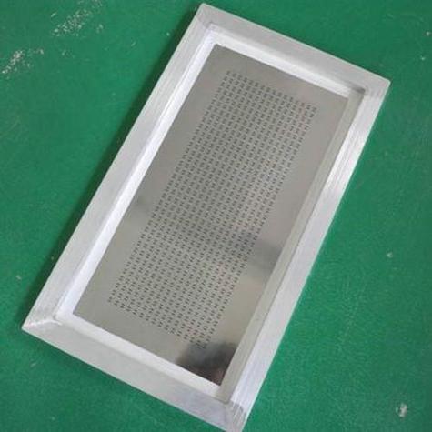
- Framed stencils, which are permanently mounted in a rigid aluminum frame. These are ideal for high-volume SMT lines because they maintain flatness and alignment over repeated use.
- Frameless stencils, also known as foil stencils. These are tensioned in a reusable frame system and are popular for flexible production environments.
- Prototype stencils, usually smaller and sometimes made from polymer materials. These support quick setup for early design validation.
- Step stencils, which have varying thicknesses in different areas to accommodate mixed component sizes on the same board.
The choice of stencil type depends on production volume, board size, and process stability requirements. For example, a framed stencil offers excellent consistency in mass production, while a frameless stencil provides faster changeover in multi-project lines.
EBest Circuit (Best Technology) frequently recommends frameless stencils for low-to-medium volume projects because they reduce storage costs and allow faster adjustments without compromising print quality.
What Is a PCB Stencil Made Of?
At its core, a PCB stencil is made of a flat metal sheet with laser-cut apertures. Stainless steel is the dominant base material, but what differentiates stencils is not just the metal itself.
Laser cutting is the preferred method for modern stencils. It produces clean aperture edges and tight tolerances, which directly affect paste release. After cutting, stencils may undergo electro-polishing to smooth the aperture walls.
Some stencils include surface coatings. Nano-coatings reduce paste adhesion, making cleaning easier and extending the time between maintenance cycles. While coatings add cost, they often pay for themselves in reduced downtime and improved consistency.
In professional assembly operations, stencil selection is treated as part of the overall process design. At EBest Circuit (Best Technology), stencil specifications are aligned with solder paste type, squeegee parameters, and reflow profiles to create a balanced, predictable system.
How to Make PCB Stencil?
Creating a circuit board stencil starts with accurate PCB design data. The stencil is derived directly from the solder paste layer in the design files, not from the copper layer.
The typical stencil fabrication process includes several steps:
- Extracting the paste layer from the PCB design files.
- Adjusting aperture sizes to match component needs.
- Laser cutting the apertures into the stencil material.
- Polishing or coating the stencil surface if required.
- Inspecting the stencil for flatness and dimensional accuracy.
At EBest Circuit (Best Technology), stencil design is reviewed as part of the PCBA preparation stage. This review ensures that stencil data reflects real assembly conditions rather than relying solely on default design outputs.
How to Cover Up Holes in a Stencil Circuit Boards?
Sometimes, certain pads or vias should not receive solder paste. In these cases, covering or blocking stencil openings becomes necessary.
Several practical methods are used:
- Modifying the stencil design to remove specific apertures.
- Applying stencil tape to temporarily block openings.
- Using removable masks designed for repeated use.
Design-level solutions are preferred whenever possible because they eliminate manual intervention. Temporary blocking methods are useful during prototyping or when accommodating last-minute changes.
In controlled production environments, EBest Circuit (Best Technology) typically addresses these needs at the design stage. This approach reduces operator error and maintains consistency across production batches.
How Thick Should a PCB Stencil Be?
PCB stencil thickness directly influences solder paste volume. Choosing the right thickness is one of the most critical stencil decisions because it affects both solder joint quality and defect rates.
Common stencil thickness values include 0.10 mm, 0.12 mm, and 0.15 mm. Thinner stencils are used for fine-pitch components, while thicker stencils support larger components and connectors.
Thickness selection depends on several factors:
- Smallest component pitch on the board.
- Pad size and shape.
- Solder paste type.
- Target production yield.
In mixed-technology boards, step stencils are often used to balance competing requirements. EBest Circuit (Best Technology) frequently recommends step stencils for boards combining fine-pitch ICs with large power components.
How to Choose the Correct Stencil?
Choosing the correct stencil requires a holistic view of the assembly process. It is not just about matching pad layouts but about supporting stable printing under real conditions.
Key considerations include:
- Board complexity and component mix.
- Production volume and changeover frequency.
- Cleaning and maintenance capabilities.
- Cost versus lifespan expectations.
How to Use PCB Stencil?
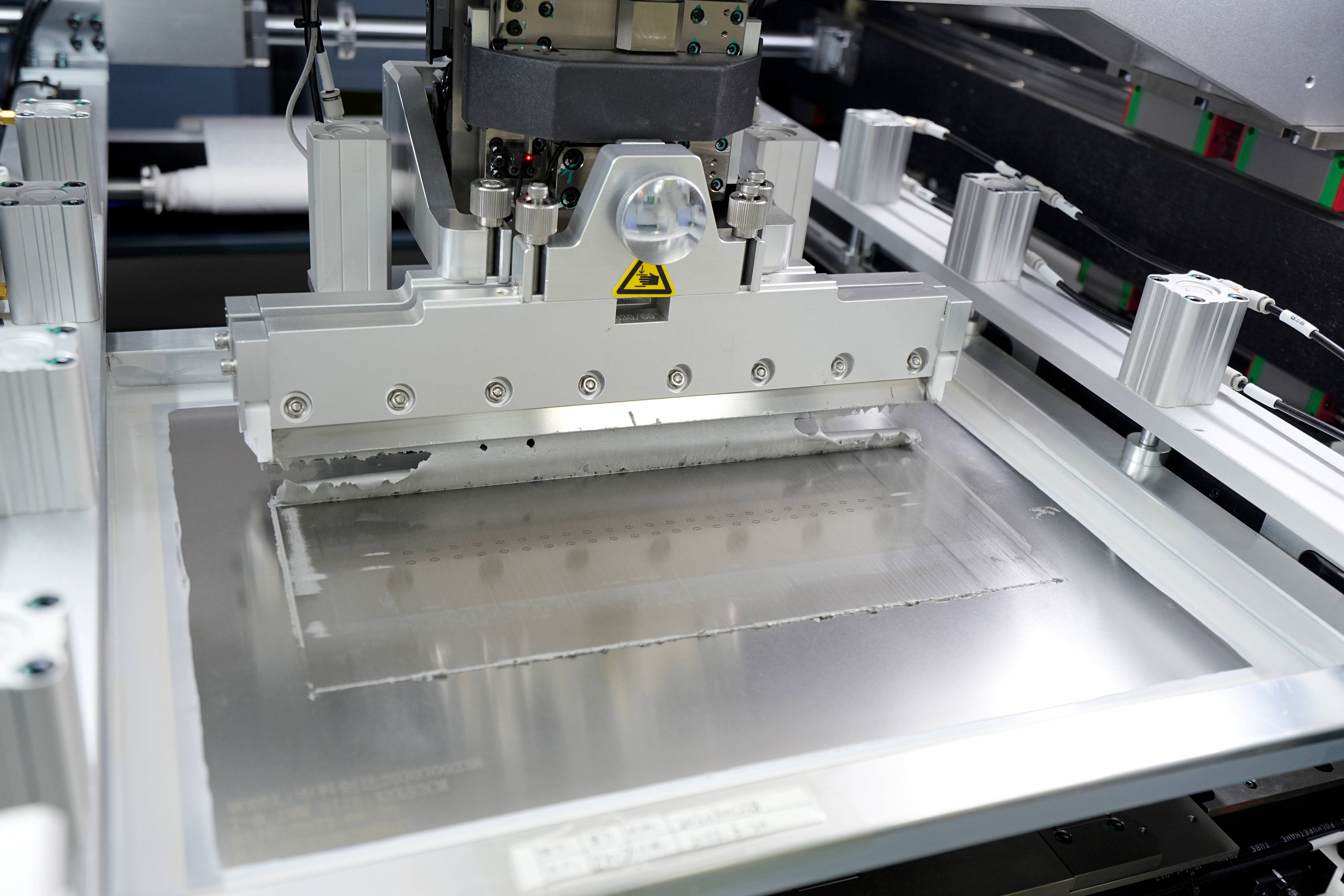
Using a PCB stencil correctly involves careful setup, alignment, and process control. The typical usage process includes:
- Securing the PCB in the printing fixture.
- Aligning the stencil apertures with the PCB pads.
- Applying solder paste evenly across the stencil.
- Using a controlled squeegee stroke to print the paste.
- Inspecting the paste deposits before component placement.
Squeegee speed, pressure, and angle should remain stable throughout production. Regular cleaning prevents paste buildup that can distort print quality.
At EBest Circuit (Best Technology), stencil printing is treated as a controlled process step. Operators follow standardized parameters, and SPI inspection is used to verify paste quality before placement begins.
Conclusion:
Circuit board stencil is more than a simple metal sheet. It is a precision tool that directly affects solder quality, assembly yield, and long-term reliability.
If you would like guidance on stencil selection, PCB fabrication, or turnkey PCBA services, contact sales@bestpcbs.com for professional support tailored to your project requirements.