Archive for August, 2021

Why most of PCB boards are green?

Tuesday, August 24th, 2021

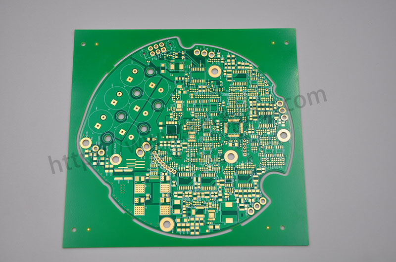
You may have found such a situation, most of the PCB boards are with green colors, while other colors are relatively rare to see, do you know why?

As we know that the Printed Circuits Board consists of Solder Mask Layer, Silk screen layer, solder PAD, Copper traces, surface finishing and other parts, etc.

Among them, the solder mask refers to the part of the PCB that is covered by oil. Since most PCB boards use green oil, the part of the green oil that can be seen on the board surface is the solder mask, which play an important role during the reflow soldering process.  

green solder mask

Then why are most of the PCB boards green? The main reasons are as follows:

  1. Green is less irritating to the eyes. We all know that green is good for the eyes and can resists fatigue. So when the PCB board with green solder mask, relative production and maintenance personnel are not prone to eye fatigue when staring at the PCB board for a long time, and it is less harmful to the eyes.

2. Cost for Green oil is lower. Since green is the mainstream in the production process, the purchase of natural green oil will be larger, and the purchase cost of green solder mask will be lower than other colors. At the same time, using the same color oil in mass production can also reduce the replacement cost.

  • When the board works on the SMT soldering process,  it needs to go through the process from Tinning, post soldering and final AOI inspection. These processes all need to be optically positioned and calibrated. The green background color is better for the recognition of the instrument.
PCBA AOI testing

Okay, now, do you understand why most of PCB boards are with green colors?

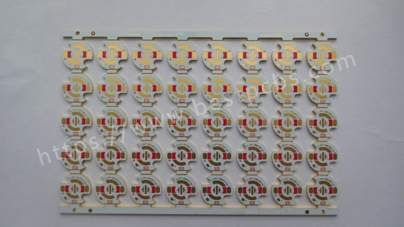
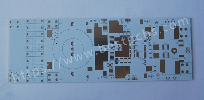
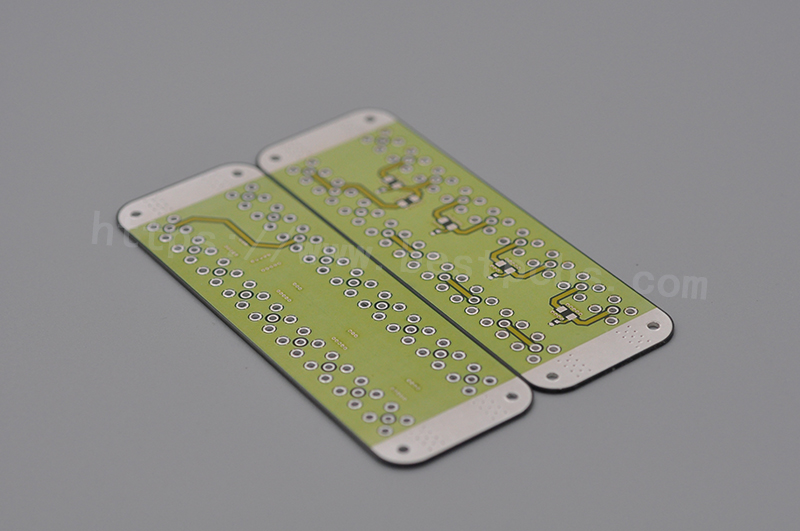
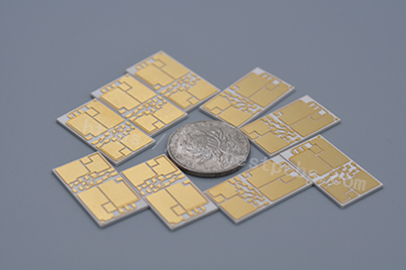
Though we know green is the most common one, but other colors such as red, yellow, blue, purple, black or some other colors are okay for us to make.

solder mask colors

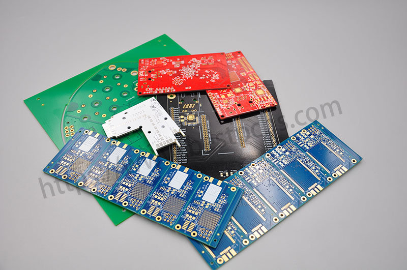
If you have PCB board with a special color want to make, please contact us and we will try best effort to meet your request.

You may also like

Advantages of Sink-pads Copper Substrate in the Field of LED Products

Tuesday, August 17th, 2021

For LED packaging, the cooling performance of the substrate will directly affect the relevant performance of the LED. Due to the low thermal conductivity of the insulation layer, the overall thermal conductivity is generally only 2~5W / (m K), which often causes high working temperature, stability and life decline of LED. Therefore, it is necessary to know the advantages of sinkpad copper substrate.

Doule sided sinkpad of copper board
  1. From the perspective of substrate, the application advantages of copper substrate in heat dissipation.

The copper substrate is used in the field of heat dissipation, mainly because the sinkpad copper substrate has the following advantages: high density, strong heat dissipation ability, the circuit part and the contact part of the products to achieve zero thermal resistance, can effectively extend the life of the products. Large power, strong thermal bearing capacity of copper substrate, according to the actual work requirements of tin spray, gold precipitation, silver plating and other effective treatment, to ensure the effectiveness of the surface treatment.

  • From the perspective of production process, the application advantages of thermal power separation copper substrate in module thermal resistance and chip temperature compared with ordinary copper substrate.

Different LED models and modules cause different thermoelectric effects. When using the common copper substrate, the junction temperature of LED chip is 72.41 ℃. However, when using the sink-pad copper substrate link, the detection shows that: the junction temperature of LED chip is 48.72 ℃. When using the common copper substrate, the thermal resistance of the module is 4.24 ℃ /W. However, after the use of sink-pad copper substrate, the overall thermal resistance of the module was detected to be 2.13 ℃ /W. Due to the different material properties, the thermal resistance of the module thermometer at the bottom of the substrate was different.  

  • From the perspective of heat dissipation theory, for the ordinary copper substrate, the diffusion path of the heat flow is the line layer (copper foil) → thermal conductivity insulation layer copper base. The interface between metal and insulation has high thermal resistance and low thermal conductivity. In the sinkpad copper substrate, the convex platform and the base are actually a whole, and most of the heat will choose to spread through the metal, and only a small amount of heat is transmitted through the interface between the metal and the insulating layer, which greatly improves the thermal conductivity of the substrate.

According to the heat dissipation theory of LED, reducing the junction temperature of LED beads can effectively improve the light output efficiency of LED, enhance the performance stability of LED, and greatly extend the service life of LED module.  

Therefore, in LED products application, the choice of thermal separated copper substrate is the best choice.

single sided sinkpad of copper board

You may also like

Baking Time & Temperature Standard of MCPCB

Tuesday, August 17th, 2021

After manufacturing the Metal Core PCB, there is a shelf life, once the shelf life has passed, we need to bake the bare board before assembling the components, otherwise the MCPCB is prone to burst when the SMT line is produced. There are industry specifications for both how long MCPCB can be stored and how long they can be baked.

MCPCB Control Standard

  1. Unpacking & Storage
  2. If the packing bag is sealed, and the manufacturing date is within 2 months, it can be directly used before assembly.
  3. The manufacturing date is within 2 months, and the unpacking date must be marked after unpacking.
  4. The manufacturing date is within 2 months, and it must be assembled and used within 5 days after unpacking.
  • Baking Time
  • If unpacked for more than 5 days within 2 months of the manufacturing date, bake at 120±5°C for 1 hour
  • Two months after the manufacturing date, baking at 120±5°C for 1 hour before assembly.
  • Two to Six months after the manufacturing date, baking at 120±5°C for 2 hours before assembly.
  • Six to Twelve months after the manufacturing date, baking at 120±5°C for 4 hours before assembly.
  • The MCPCB after baking must be used up within 5 days (put into IR REFLOW), and unused board must be baked for another hour before assembly.
  • Over half one year after the manufacturing date, bake at 120±5°C for 4 hours before assembly, and then send it to the production line to do HASL_LF before using.
Baking Machine

Preservation & Baking Standard for in different regions

The specific storage time and baking temperature of MCPCB are not only related to the production capacity and production process of manufacturer, but also have a great relationship with the region.

  1. For areas with heavier humidity, the MCPCB must be used up within 24 hours when exposed to the air, otherwise it is easy to oxidize. After normal opening, it is best to use it up in 8 hours.
  • For areas with a relatively dry climate, the preservation time of PCB will be longer, and the baking time can also be shorter. The baking temperature is generally 120±5°C, and the baking time is determined according to the specific situation.

The MCPCB with OSP or Gold Immersion has a shelf life of 6 months after packaging, and it is generally not recommended to bake for MCPCB with OSP.

PCB board with SMT

If you have other questions about MCPCB, welcome to contact us.

You may also like

Why use ceramic circuit boards

Wednesday, August 11th, 2021

With the continuous upgrading and optimization of electronic products, the PCBs as the carrier of components have also been continuously improved, and ceramic circuit boards have appeared. So, compared with traditional glass fiber (FR-4), aluminum-based and copper-based, what’s the advantages of ceramic PCB?

1. Stable flatness

Ordinary PCB is usually made by bonding copper foil and substrate, and the substrate material is mostly glass fiber (FR-4), phenolic resin (FR-3), aluminum-based, copper-based, PTFE, composite ceramics and other materials. The mixture is usually phenolic, epoxy, etc. Due to thermal stress, chemical factors, improper production technology and other reasons during PCB processing, or due to asymmetric copper paving on both sides during the design process, it is easy to cause the PCB board to warp to varying degrees.
The ceramic circuit board is hard with good heat dissipation performance, and low thermal expansion coefficient. At the same time, the ceramic circuit board is bonded to the base material by magnetron/vacuum sputtering. The bonding force is strong and the copper foil will not fall off. High reliability, thus avoiding the

2. Large current carrying capacity:

100A current continuously passes through the 1mm 0.3mm copper board, and the temperature rise is about 17°C; 100A current continuously passes through the 2mm 0.3mm board, and the temperature rise is only about 5°C.

3. Thermal conductivity:

The thermal conductivity of alumina can reach 15~35, and that of aluminum nitride can reach 170~230. Because in the case of high bonding strength, its thermal expansion coefficient will be more matched, and the tested tensile value can reach 45 MPa.

4. Thermal conductivity:

The thermal conductivity of the high thermal conductivity aluminum substrate is generally 1-4W/M. K, and the thermal conductivity of the ceramic substrate can reach about 220W/M. K depending on its preparation method and material formula.

5. Low thermal resistance:

The thermal resistance of a 10—10mm ceramic substrate is 0.63mm thick. The thermal resistance of a ceramic substrate is 0.31K/W, the thermal resistance of a 0.38mm thick ceramic substrate is 0.19K/W, and the thermal resistance of a 0.25mm thick ceramic substrate is 0.14K /W.
 

6. Good insulation performance, high pressure resistance, protection of personal safety and equipment, strong bonding force, bonding technology, copper foil will not fall off, high reliability, stable performance in high temperature and high humidity environments.

7. Stable high-frequency performance, AK and DK values are lower than its PTFE, in line with ceramics.

In summary, with its advantages, ceramic circuit boards have been used in high-power power electronic modules, solar panel components, high-frequency switching power supplies, solid state relays, automotive electronics, aerospace, military electronics, high-power LED lighting products, and communications Antennas, automotive sensors, refrigeration sheets and other fields are widely used.

DSC-1135
DSC-1186

You may also like

What kind of test for Coil Printed Circuit Board?

Wednesday, August 11th, 2021

In year 2019, one of our US customers asked us, Marina can Best Technology make a Coil PCB (Printed Circuit Board) with FR4 material? Yes, of course, we can make different kinds of PCB for our customer, included for the Coils PCB, which currently is widely used for wireless charging and antenna products. Please see the following Coils board from Best Technology.

The manufacturing process is same as other PCB manufacturing process, and just make sure the etching process and pay attention for the etching tolerance of the coils trace. And when coils PCB board finished, do you know what kind of test need to do to check the functional of Coils boards?

Today I would like to share how Best Technology test Coil PCB board. Everyone knows that we check the quality of PCB board with Flying probe tester, as the production efficiency is extremely low and the inductance and capacitance cannot be accurately measured. In this way, we need to use LCR meter to make verify the inductance and capacitance. See the LCT meter as following.

Best Technology chooses the digital meter LCR Meter to test the impedance characteristics of the coil. From the LCR tester you know see two numbers, one for inductance and another for resistance.

After test each coils printed circuit board, we will make record at our paper to make sure every measurement data will meet for customer requirement.

Currently, LCR Meter only provides a single-channel test function, and can only test the impedance characteristics of a set of coils at a time. But this is the effective test method for Coil printed Circuit Board. But we believe we will buy more LCR meters to let the test coil board become quicker.

If you have any comments on the testing for Coil printed circuit board, you are welcome to send us query and we are happy to discuss with you. You can visit www.bestpcbs.com to know more about us. Thank you

You may also like