

Want a bright LED PCB? Explore its design techniques, manufacturing standards, driver integration, quality controls and selection manufacturer tips.
EBest Circuit (Best Technology) delivers bright LED PCB with unmatched speed, solving critical industry pain points like delayed prototyping and missed deadlines. Our 24-hour rapid prototyping and 3–5-day bulk production cycles slash development time by 70% compared to industry averages. With ISO 9001-certified automated lines and local material procurement networks, we eliminate supply chain delays while achieving 99.98% on-time delivery rates. Real-time production tracking and same-day design-for-manufacturability reviews accelerate iterations – 85% of clients finalize designs within two revisions. For urgent bright LED PCB projects, our express service guarantees functional prototypes shipped within 24 hours (3-layer boards) with ≤10μm alignment accuracy, backed by IPC-A-610 Class 3 standards. Custom LED driver integration and thermal simulations come standard, reducing your time-to-market by 4–6 weeks. Contact us today if you have any request for bright LED PCB: sales@bestpcbs.com.
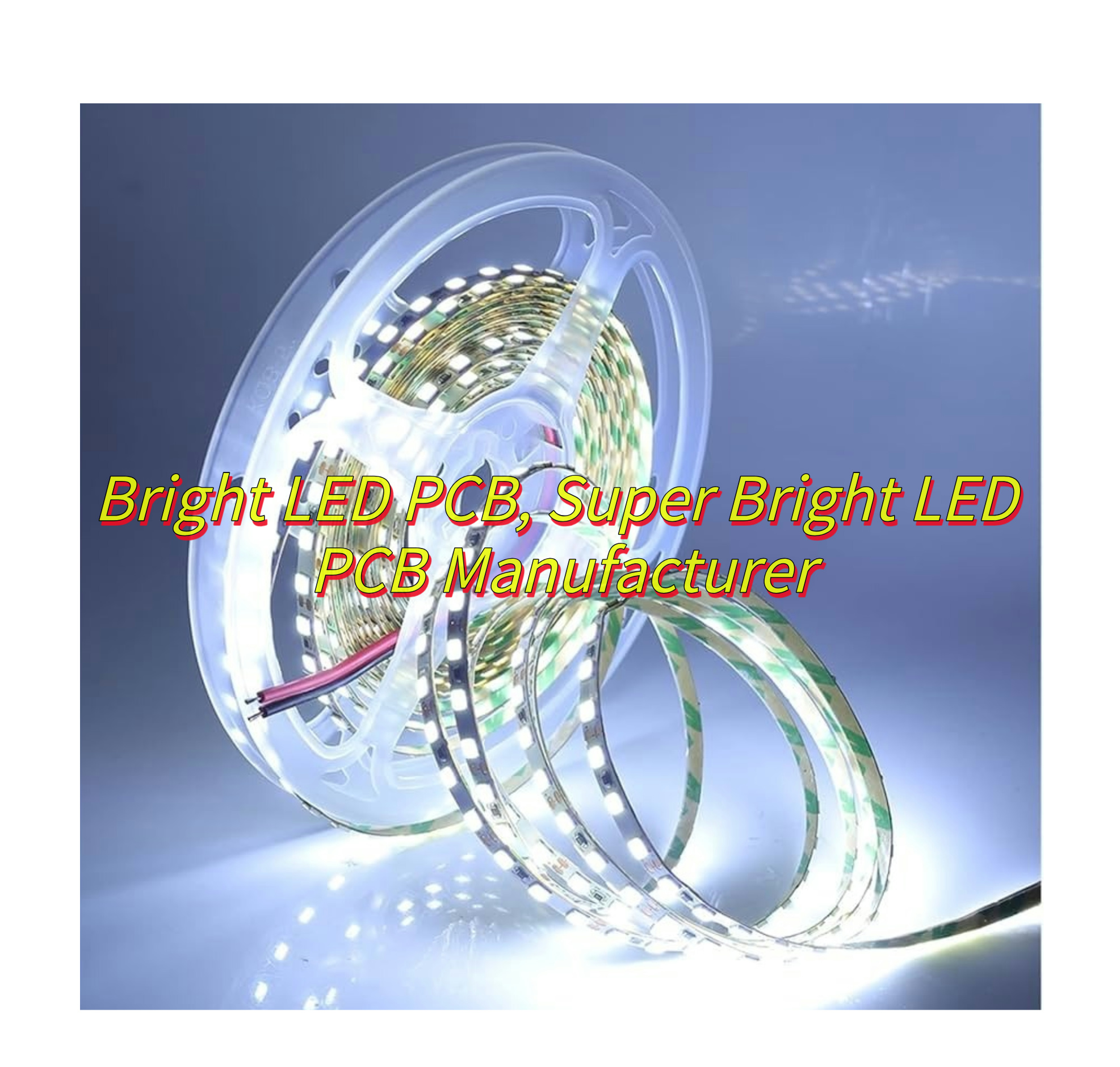
What Is A Bright LED PCB?
A bright LED PCB is a printed circuit board engineered specifically to handle high-luminosity LEDs by resolving their intense thermal output and electrical requirements. Unlike standard PCBs, bright LED PCB boards utilize metal-core substrates like aluminum or copper, which rapidly transfer heat away from LED junctions to prevent efficiency loss or premature failure. Their layered design often incorporates thermal vias, thick copper traces, and dielectric materials optimized for heat spreading, paired with precision-mapped component placement to avoid localized overheating. These adaptations enable sustained maximum brightness in applications such as stadium lighting, automotive headlamps, and surgical equipment, where both radiant output and operational stability are non-negotiable. Manufacturers further reinforce durability through techniques like ceramic-filled solder masks and conformal coatings to withstand vibration, moisture, and thermal cycling stresses inherent in high-intensity environments.
How to Optimize Thermal Management of Bright LED PCB?
Below is how to optimize thermal management of bright LED PCB:
Start with Thermally Enhanced Materials
- Use metal-core PCBs (MCPCBs) like aluminum or copper-clad boards to conduct heat 5–8x faster than standard FR-4. For extreme brightness, opt for ceramic-filled composites (e.g., AlN) with 90+ W/mK thermal conductivity.
- Choose high-TG laminates (≥170°C) to prevent delamination under prolonged LED heat exposure.
Design for Airflow and Convection
- Orient bright LED PCB vertically in enclosures to leverage natural convection. Add 2–4mm gaps between boards to avoid heat stacking.
- Incorporate cutouts or channels between LED rows to direct airflow. Pair with low-profile fans (20mm×20mm) for targeted cooling if space allows.
Maximize Heat Dissipation Paths
- Flood unused PCB areas with thermal vias (0.3mm diameter, spaced 1–2mm apart) to wick heat to inner layers or heatsinks.
- Use thick copper layers (2–4oz) for power traces to minimize electrical resistance and heat buildup.
Upgrade Passive Cooling
- Attach extruded aluminum heatsinks (≥15mm height) with 1.5–2°C/W thermal resistance. For compact designs, use skived fins or vapor chambers.
- Apply graphite thermal pads (8–12W/m·K) between LEDs and heatsinks for gap-free heat transfer—ideal for uneven surfaces.
Optimize LED Placement and Spacing
- Group high-power bright LED PCB sections away from heat-sensitive components (drivers, capacitors). Maintain ≥10mm clearance from temperature-sensitive areas.
- Alternate LED orientations to spread heat evenly. Avoid clustering high-lumen LEDs in dense arrays.
Leverage Advanced Thermal Interfaces
- Use phase-change materials (PCMs) (e.g., 3–5W/mK) that melt at 45–50°C to fill micro-gaps. Replaces traditional thermal pads for 10–15% lower thermal resistance.
- For SMD LEDs, opt for solderable thermal tabs instead of pads to reduce contact resistance by 30%.
Test Under Real-World Conditions
- Validate designs with infrared (IR) thermography to identify hotspots exceeding 85°C. Adjust cooling if any LED junction temperature approaches 120°C.
- Run accelerated life tests (85°C/85% RH, 1,000+ hours) to predict lumen depreciation. Aim for <10% brightness loss over 10,000 hours.
Incorporate Thermal Protection
- Add NTC thermistors near LED clusters to trigger dimming or shutdown if temperatures exceed safe limits (e.g., 90°C).
- Use fuses with thermal derating to cut power during overheating, preventing irreversible damage to Bright LED PCB components.

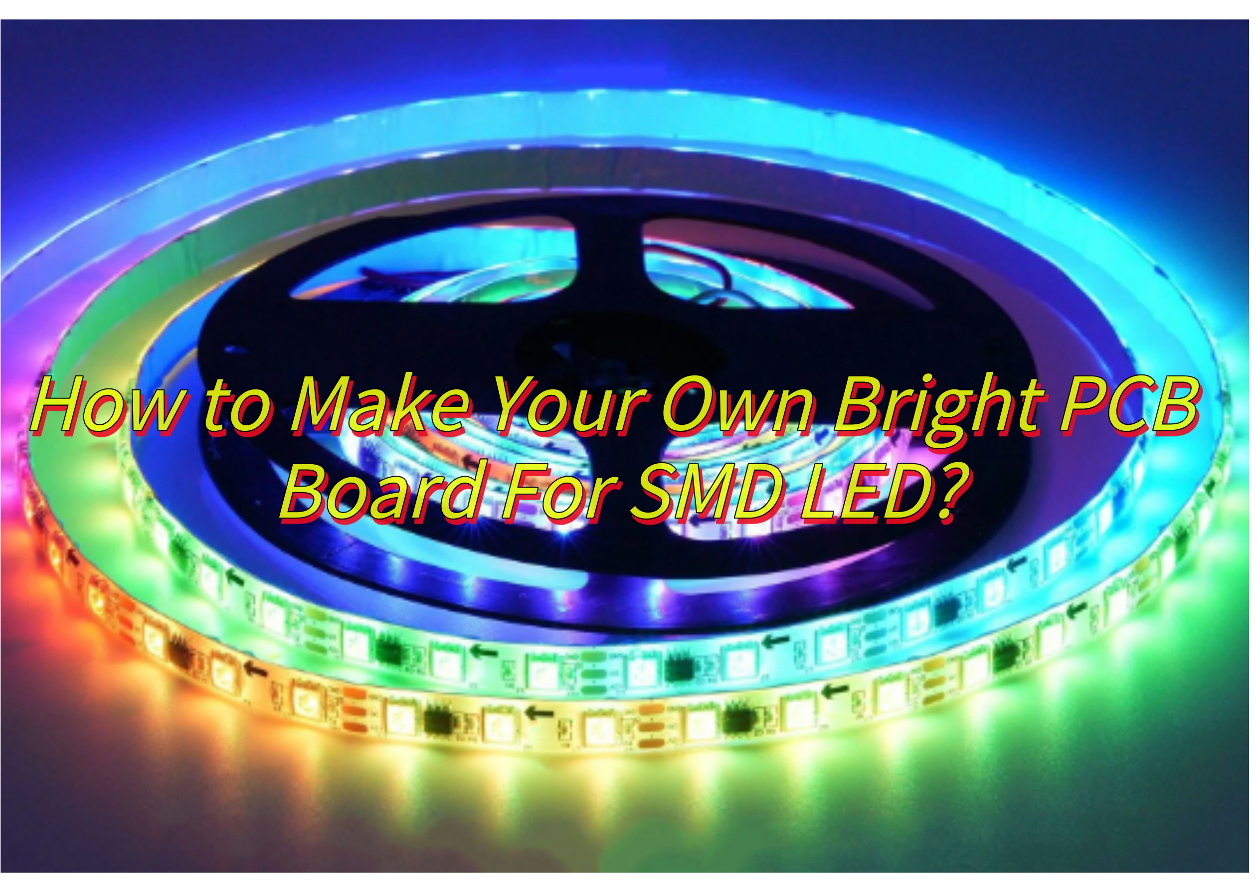
How to Make Your Own Bright PCB Board For SMD LED?
Here’s how to make your own bright PCB board for SMD LED:
1. Design the Circuit Layout
- Use PCB design software to sketch your circuit.
- Place SMD LEDs in a grid or pattern for even light distribution. Leave spacing between LEDs to prevent overheating.
- Add current-limiting resistors (calculate value based on LED specs and power supply voltage).
- Include wide traces for power lines to minimize voltage drop and ensure consistent brightness.
2. Select Materials Wisely
- Base Material: Choose FR-4 fiberglass for durability and heat resistance.
- Copper Thickness: Choose 1oz (35μm) copper cladding for balanced conductivity and cost.
- Solder Mask: Use a white solder mask to reflect light and enhance brightness.
- Surface Finish: Select ENIG (Electroless Nickel Immersion Gold) for excellent solderability and longevity.
3. Fabricate the PCB
Etching Method:
- Homebrew Option: Use the toner transfer method with glossy paper and ferric chloride etchant.
- Precision Tip: For sharp traces, apply even pressure during ironing and agitate the etchant gently.
- Drilling: Use a 0.8mm drill bit for LED pads and 1.0mm for via holes.
- Cleaning: Scrub with acetone and a brush to remove residue after etching.
4. Solder SMD LEDs Properly
Tools: Use a fine-tipped soldering iron (30W) or hot air rework station for tiny components.
Technique:
- Check for bridges or cold joints under a magnifying glass.
- Apply flux to pads before placing LEDs.
- Tack one pad first, then solder the opposite side to avoid shifting.
- Reflow solder joints with a hot air gun for smooth, void-free connections.
5. Power and Test
Power Supply: Use a lab bench supply or battery with current limiting (e.g., 5V for standard LEDs).
Testing:
- Power the board in stages to avoid sudden current surges.
- Measure voltage drops across resistors with a multimeter.
- Adjust brightness by swapping resistors or modifying PWM settings (if using a microcontroller).
6. Enhance Performance
- Thermal Management: Add copper pours under LEDs or attach a thin aluminum heat sink.
- Diffusion: Apply a semi-transparent epoxy or laser-cut acrylic layer for soft, even light.
- Protection: Coat the board with conformal spray to guard against moisture and dust.
7. Troubleshooting Tips
- Dim LEDs: Check resistor values, solder joints, or power supply stability.
- Flickering: Look for loose connections or inadequate decoupling capacitors.
- Overheating: Reduce current or increase copper trace width.
How to Integrate Driver Circuits for Maximum LED Brightness on PCBs?
Here’s an expanded guide to integrating driver circuits for maximum LED brightness on PCBs:
1. Choose the Right Driver Type
Linear Drivers: Best for low-power LEDs (e.g., indicator lights). Devices like the AMS7135 offer simple, fixed-current output but generate more heat.
Switch-Mode Drivers: Essential for high-power LEDs. Select based on your power needs:
- Buck Converters: Reduce voltage (e.g., 12V to 5V for LEDs).
- Boost Converters: Increase voltage (e.g., 3.3V to 12V for LEDs).
- Buck-Boost Converters: Handle varying input voltages.
2. Optimize Current Delivery
- Sense Resistors: Use precision resistors (1% tolerance) to set LED current. Lower resistance values reduce power loss but require more sensitive drivers.
- Trace Width: Design power traces to handle full LED current. Use 30–40mil traces for high-power LEDs to minimize voltage drop.
- Star Grounding: Connect all driver grounds to a single point to prevent noise and ground loops.
3. Enhance Thermal Performance
- Thermal Vias: Add multiple vias under the driver and LED pads to conduct heat to inner PCB layers.
- Heat Sinks: Attach small aluminum heat sinks to drivers and high-power LEDs. Use thermal tape or grease for better contact.
- Copper Pours: Use thick copper layers (2oz or more) under LEDs and drivers to spread heat.
4. Improve Power Quality
- Input Capacitors: Place high-quality capacitors (e.g., 22μF ceramic) near the driver’s power input to filter noise.
- Output Filtering: Add a small capacitor (0.1μF–1μF) across LED terminals to smooth current spikes.
- Fuse Protection: Include a resettable fuse in series with LEDs to prevent overcurrent damage.
5. Dimming and Control Strategies
- PWM Dimming: Use a microcontroller to generate PWM signals (1kHz–20kHz) for brightness control. Higher frequencies reduce flicker.
- Analog Dimming: Adjust LED brightness by varying current. Use a digital potentiometer for smooth transitions.
- Color Mixing: For RGB LEDs, use independent driver channels to adjust each color’s intensity precisely.
6. Layout Best Practices
- Component Placement: Keep drivers close to LEDs to minimize trace length. Avoid routing high-current traces near sensitive analog components.
- Signal Integrity: Shield PWM signals from noisy areas (e.g., inductors) using ground traces.
- Testing Pads: Include unpopulated footprints for test points near critical nodes (e.g., LED current sense pins).
7. Protection and Reliability
- Reverse Polarity Protection: Add a diode in series with the input to prevent damage from reversed power connections.
- Overvoltage Clamping: Use a Zener diode across LEDs to limit voltage spikes.
- Thermal Shutdown: Choose drivers with built-in thermal protection to prevent overheating.
8. Advanced Techniques
- Hybrid Dimming: Combine PWM and analog dimming for ultra-wide brightness ranges.
- Predictive Maintenance: Monitor LED temperature with an NTC thermistor to detect degradation early.
- Modular Design: Create separate driver modules for each LED channel to simplify troubleshooting and replacement.

How to Choose A Super Bright LED PCB Manufacturer?
Here’s how to select a super bright LED PCB manufacturer for high-brightness LED PCBs, focusing on practicality and actionable advice:
Evaluate Technical Expertise
- LED-Specific Experience: Prioritize manufacturers with a proven track record in LED lighting or automotive headlight PCBs. Ask for case studies or client references.
- Thermal Management Capabilities: Ensure they offer aluminum-core PCBs, thick copper layers (2oz+), and embedded heat vias to handle high-power LED heat dissipation.
- Material Options: Confirm they work with high-reflectivity white solder masks and low-loss dielectric materials to maximize light output.
Quality Control and Certifications
- Industry Standards: Look for certifications like UL, ISO 9001, and IATF 16949 (for automotive applications). Ask about their process for flux residue removal, which can affect LED performance.
- Testing Protocols: Inquire about in-house testing capabilities, including thermal cycling, optical brightness measurements, and solder joint integrity checks.
- Component Sourcing: Verify they use reputable suppliers for LED drivers, capacitors, and inductors to ensure long-term reliability.
Design for Manufacturability (DFM) Support
- Engineering Collaboration: Choose a manufacturer that offers free DFM reviews to identify potential issues like trace width limitations or improper thermal via placement.
- Customization Flexibility: Ensure they can handle complex designs (e.g., multi-layer boards with blind/buried vias) and tight tolerances for LED spacing.
- Panelization Options: Confirm they support custom panelization to reduce per-unit costs while minimizing stress on LEDs during assembly.
Production Capacity and Scalability
- Lead Times: Request typical lead times for prototypes (5–10 days) and mass production (2–4 weeks). Avoid suppliers with excessively long queues.
- Volume Flexibility: Choose manufacturers that accommodate both small-batch prototypes (10–50 units) and large-scale orders (10,000+ units) without quality compromises.
- Equipment Modernity: Check if they use automated optical inspection (AOI) and selective soldering machines to ensure consistency.
Cost Transparency
- Pricing Breakdown: Request a detailed quote itemizing material costs (e.g., aluminum base, copper thickness), labor, and testing. Beware of hidden fees for engineering changes.
- Value Engineering: Look for partners who suggest cost-saving alternatives (e.g., thinner copper layers for low-power LEDs) without sacrificing performance.
- Bulk Discounts: Negotiate tiered pricing for repeat orders, especially if your project requires ongoing production.
Customer Service and Communication
- Project Management: Ensure dedicated engineers are assigned to your account for real-time updates and quick issue resolution.
- Language Proficiency: Confirm they offer English-speaking support if you’re working internationally.
- After-Sales Support: Inquire about warranty policies (typically 1–3 years) and procedures for addressing defective boards.
Sustainability Practices
- RoHS Compliance: Verify lead-free manufacturing processes and hazardous substance restrictions.
- Waste Management: Ask about recycling programs for scrap metal and solder dross.
- Energy Efficiency: Prefer manufacturers using renewable energy or LEED-certified facilities.
Prototyping and Iteration
- Rapid Prototyping: Test their ability to deliver functional prototypes within 3–5 days for design validation.
- Revision Cycle: Confirm they offer affordable re-spins (typically 50–200 per revision) to refine your design based on test results.
- Sample Policy: Request free sample boards to evaluate solder mask quality, trace alignment, and thermal performance.
What Quality Standards Ensure Reliability in Super Bright LED PCB Manufacturing?
Here’s a detailed breakdown of quality standards and practices that ensure reliability in super bright LED PCB manufacturing:
Adherence to Industry Standards
- IPC-A-600/IPC-6012: These standards define acceptability criteria for PCBs, including trace spacing, via integrity, and solder mask adhesion. Ensure your manufacturer complies with Class 3 requirements for high-reliability electronics.
- UL 796: Certifies PCBs for electrical safety, flame resistance, and thermal endurance. Look for UL-approved materials like FR-4 or high-TG laminates.
- ISO 9001: Validates the manufacturer’s quality management system, covering processes from design to delivery.
Material Quality Controls
- Base Material: Specify high-performance substrates like aluminum-core PCBs or ceramic-filled composites for superior thermal conductivity.
- Copper Purity: Require 99.9% pure electrolytic copper to minimize resistance and heat generation.
- Solder Mask: Insist on white LPI solder masks with ≥85% reflectivity to maximize light output.
Manufacturing Process Standards
- Etching Precision: Ensure trace/space tolerances of ±0.05mm using LDI (laser direct imaging) to maintain current delivery consistency.
- Plating Thickness: Require 25–50μm copper plating in via barrels to prevent thermal stress fractures.
- Surface Finish: Mandate ENIG (Electroless Nickel Immersion Gold) for flat, solderable surfaces that resist corrosion.
Thermal Management Protocols
- Thermal Via Testing: Verify via conductivity using micro-sectioning to confirm solder wicking and absence of voids.
- Delta-T Testing: Measure temperature rise across LED junctions during prolonged operation (e.g., 48-hour burn-in).
- Heat Spreader Adhesion: Ensure aluminum cores are bonded with ≥1.5N/mm² adhesive strength to prevent delamination.
Electrical and Optical Testing
- Flyprobe Testing: Use flying probe machines to check for opens/shorts with ≤2Ω resolution.
- IV Curve Tracing: Validate LED forward voltage (Vf) and current (If) against datasheet specifications.
- Lumen Maintenance Testing: Accelerate aging with high-temperature storage (85°C/85% RH) to predict lumen depreciation over 10,000+ hours.
Environmental Compliance
- RoHS/REACH: Confirm lead-free manufacturing and absence of restricted substances like cadmium or hexavalent chromium.
- Conflict Minerals: Require DFARS compliance for tin/tantalum sourcing to avoid ethical supply chain issues.
- Halogen-Free: Specify halogen-free solder masks and laminates to reduce toxic emissions during combustion.
Reliability Engineering Practices
- HAZOP Studies: Conduct hazard and operability analyses to identify failure modes (e.g., LED solder joint fatigue).
- FMEA: Implement failure mode and effects analysis to prioritize mitigations for high-risk components.
- DOE: Use design of experiments to optimize parameters like copper weight, trace geometry, and solder paste stencil thickness.
Audit and Certification Requirements
- Factory Audits: Require ISO/TS 16949 certification for automotive-grade PCBs or AS9100 for aerospace applications.
- First Article Inspection (FAI): Validate the first production run against 3D CAD models and electrical specifications.
- Certificates of Conformance (CoC): Demand material certs for all laminates, copper foils, and solder pastes used.
How to Maintain Brightness Consistency in LED PCB Bulk Production?
Here’s a structured guide to maintaining brightness consistency in bright LED PCB bulk production, focusing on actionable steps and practical solutions:
1. Strict LED Binning and Sorting
- Pre-Production Screening: Require LED suppliers to provide components sorted by luminous flux (lm), wavelength (nm), and forward voltage (Vf) within ±5% tolerance.
- Vendor Audits: Regularly audit suppliers’ binning processes to ensure compliance with ANSI/IES LM-80 standards for lumen maintenance.
- In-House Sorting: Use integrating spheres or spectrometers to re-test random samples from each reel for spectral and brightness consistency.
2. PCB Design Optimization
- Thermal Balancing: Design symmetrical copper pours and thermal vias to ensure equal heat dissipation across all LED positions.
- Trace Matching: Maintain identical trace lengths (±0.5mm) and widths for all LED power lines to prevent current imbalances.
- Component Placement: Use automated placement machines with ±0.05mm accuracy to align LEDs consistently relative to optical components (e.g., lenses).
3. Process Control in Assembly
- Solder Paste Consistency: Use laser-cut stainless-steel stencils with optimized aperture ratios (e.g., 1:1 for LED pads) to control solder volume.
- Reflow Profiling: Implement tight reflow oven temperature curves (±2°C setpoint tolerance) to minimize voiding and solder joint variability.
- Automated Optical Inspection (AOI): Deploy AOI systems with LED-specific algorithms to detect polarity reversals, tombstoning, and solder bridges.
4. Driving Circuit Calibration
- Current Matching: Program LED drivers with ±2% current accuracy using DAC-controlled resistors or digital potentiometers.
- PWM Synchronization: For multi-channel designs, synchronize PWM signals to <1μs phase difference to eliminate flicker and brightness variation.
- Voltage Compensation: Add feedback loops to adjust current dynamically based on real-time Vf measurements.
5. Environmental and Testing Controls
- Temperature-Controlled Chambers: Test PCBs at 25°C ±1°C to eliminate thermal drift effects on LED output.
- Lumen Maintenance Burn-In: Operate LEDs at 85°C for 100+ hours to weed out early failures (infant mortality) before shipping.
- Optical Inspection Stations: Use goniophotometers or 2D light meters to map luminous intensity distributions and identify outliers.
6. Data-Driven Quality Management
- Statistical Process Control (SPC): Track main parameters (e.g., LED Vf, solder paste volume) using control charts with ±3σ limits.
- Traceability Systems: Implement laser-etched 2D barcodes to link each PCB to its production data (machine settings, test results).
- Root Cause Analysis: Use Pareto charts to identify top failure modes (e.g., 40% of brightness variance due to solder voids).
7. Supplier and Material Management
- Second-Sourcing Strategy: Qualify multiple LED suppliers but require identical binning codes to simplify substitution.
- Material Lot Tracking: Segregate PCBs by laminate lot, solder paste batch, and stencil serial number during production.
- Shelf-Life Compliance: Rotate LED reels every 3 months (or per manufacturer specs) to avoid degradation from moisture absorption.
8. Operator Training and Tools
- Certification Programs: Train assemblers on LED-specific SMT best practices, including nozzle selection and pick-and-place force calibration.
- Cross-Referencing Tools: Equip technicians with LED test jigs to compare brightness against a golden sample board.
- Escalation Protocols: Define clear steps for operators when brightness variance exceeds 5% (e.g., halt line, notify engineering).
How to Make PCB LED Brighter on Mechanical Keyboard?
Here’s how to make PCB LED brighter on mechanical keyboard:
Upgrade LED Specifications
- High-Lumen LEDs: Replace stock LEDs with models rated for higher millicandela (mcd) output (e.g., 3000–5000 mcd vs. standard 1500 mcd).
- Color Selection: Choose “cool white” or “pure white” LEDs, which typically appear brighter than warm white variants due to higher color temperature (5000K–6500K).
- Voltage Matching: Ensure new LEDs match your PCB’s voltage requirements (e.g., 3.2V–3.4V for SMD 3528 LEDs) to avoid dimming from underpowering.
Optimize Current Delivery
- Resistor Adjustments: Lower the value of current-limiting resistors (e.g., from 68Ω to 47Ω) to increase current flow, but stay below the LED’s maximum rated current (usually 20mA).
- Parallel Wiring: Rewire LEDs in parallel instead of series to reduce voltage drop across multiple keys. Use a heavier gauge trace for the common cathode line.
- Thicker Traces: Route power traces with 20–30mil width to minimize resistance and ensure consistent current to all LEDs.
Improve PCB Reflectivity
- White Solder Mask: Use a white solder mask instead of black or green to reflect more light upward. Confirm your PCB manufacturer offers this option.
- Copper Pours: Add a solid ground plane under the LEDs to act as a heat sink and reflector. Ensure it’s connected to the PCB’s ground with multiple thermal vias.
- Diffuser Mods: Apply a thin layer of translucent epoxy or laser-cut acrylic diffusers over LEDs to soften hotspots and improve perceived brightness.
Enhance Thermal Management
- Aluminum Plates: Replace the PCB’s stock FR-4 material with an aluminum-core PCB to dissipate heat more efficiently, allowing higher safe current levels.
- Heat Sinks: For SMD LEDs, attach 1mm×1mm silicone thermal pads to the PCB’s bottom layer to conduct heat away from components.
- Airflow Hacks: Position the keyboard on a stand or add rubber feet to elevate it, improving natural convection cooling during extended use.
Firmware/Software Tweaks
- PWM Adjustments: If your keyboard supports QMK/VIA firmware, increase the LED PWM duty cycle (e.g., from 50% to 80%) in the configuration file.
- Layer-Specific Brightness: Program unused layers to default to maximum brightness, bypassing default energy-saving modes.
- Debounce Fixes: Reduce key debounce delays to prevent LED flicker during rapid typing.
Physical Modifications
- Lens Polishing: Gently clean LED lenses with isopropyl alcohol and a microfiber cloth to remove oxidation or residue that might block light.
- Switch Mods: Use switches with translucent housings to allow more light to escape through the keycaps.
- Keycap Swaps: Choose double-shot PBT keycaps with thin walls or “shine-through” legends to maximize light transmission.
Testing and Validation
- Current Measurement: Use a multimeter to check LED current after resistor changes. Aim for 18–20mA per LED to balance brightness and longevity.
- Thermal Cameras: Spot-check LED temperatures after 30 minutes of use. Ensure they stay below 60°C to prevent degradation.
- A/B Comparisons: Test brightness in a dark room using a lux meter app. Compare results to stock LEDs to quantify improvements.
Safety Precautions
- Polarity Checks: Always verify LED orientation with a diode tester before soldering to avoid reverse-voltage damage.
- ESD Protection: Use an anti-static wrist strap when handling LEDs to prevent electrostatic discharge failures.
- Warranty Considerations: Modifying LEDs may void your keyboard’s warranty. Check the manufacturer’s policy before proceeding.