


What Does SMD Stand For? The Core Definition of Surface Mount Device
At its simplest, SMD (Surface Mount Device) is an electronic component designed to be soldered directly onto the surface of a printed circuit board (PCB). Unlike traditional through-hole components that require drilling holes for lead insertion, SMDs use small metal pads or terminals to attach to PCB surfaces—eliminating the need for drilling and unlocking game-changing design possibilities. This compact packaging is why your smartphone fits in your pocket, your laptop stays lightweight, and modern electronics keep shrinking while packing more power. From resistors and capacitors to integrated circuits, SMDs are the building blocks of nearly every device we use today, from consumer gadgets to aerospace systems.
SMD vs. SMT: Clearing Up the Most Common Confusion
One of the biggest frustrations for electronics beginners (and even seasoned hobbyists) is mixing up SMD and SMT. Let’s break it down plainly:
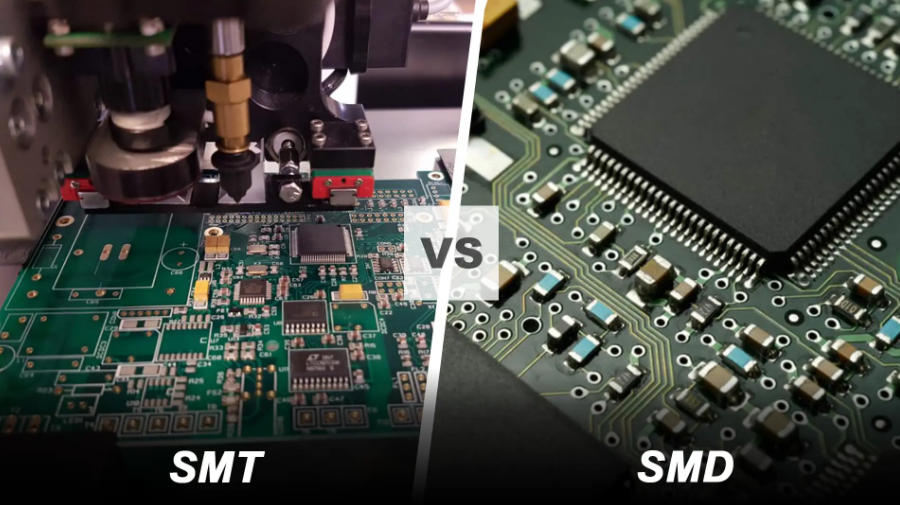
- SMD: The component itself—think of it as the “part” you’re working with (e.g., an SMD resistor or LED).
- SMT: Surface Mount Technology—the process of placing and soldering SMDs onto a PCB.
To put it metaphorically: SMDs are the bricks, and SMT is the construction method used to build the wall (the PCB). This distinction matters because choosing the right SMD components means understanding how they’ll interact with SMT assembly—whether you’re prototyping at home or scaling production. Unlike through-hole technology, SMT with SMDs enables faster automation, higher component density, and smaller final products—though it does come with unique challenges like precision requirements.
Key Characteristics of SMD Components That Transform Electronics
What makes SMD technology so revolutionary? These core traits explain its dominance in modern electronics:
- No Drilling Required: SMDs attach directly to PCB surfaces, simplifying manufacturing and reducing PCB costs.
- Compact & Lightweight: Without bulky leads, SMDs are drastically smaller—some resistors are smaller than a grain of rice—allowing denser circuit layouts.
- Dual-Sided Mounting: SMDs can be placed on both sides of a PCB, doubling component capacity without increasing size.
- Better High-Frequency Performance: Short leads minimize parasitic inductance and capacitance, making SMDs ideal for high-speed circuits (e.g., 5G devices or RF equipment).
- Automation-Friendly: Designed for robotic pick-and-place machines, SMDs speed up production and reduce human error in mass manufacturing.
Where Are SMDs Used? Real-World Applications Across Industries
SMD components aren’t just for tech geeks—they’re everywhere. Here are the industries relying most on this technology:
- Consumer Electronics: Smartphones, laptops, tablets, and wearables depend on SMDs to stay slim and powerful.
- Automotive: Modern cars use hundreds of SMDs in ECUs (Engine Control Units), infotainment systems, and safety features (e.g., airbag sensors).
- Medical Devices: Compact, reliable SMDs enable portable monitors, pacemakers, and diagnostic equipment.
- Aerospace & Defense: Satellites and aircraft use SMDs for their lightweight design and resistance to vibration.
- Telecommunications: 5G base stations, routers, and switches use SMDs to handle high-frequency signals efficiently.
How to Read SMD Resistor Codes (A Practical Guide)
One of the most common Reddit complaints about SMD components is deciphering their tiny codes—since their small size rules out printed values like traditional resistors. Here’s a step-by-step breakdown:
3-Digit Codes
The first two digits are significant figures; the third is the multiplier (number of zeros to add). For example:
- 102 = 10 × 10² = 1,000 ohms (1kΩ)
- 473 = 47 × 10³ = 47,000 ohms (47kΩ)
- R22 = 0.22 ohms (the “R” denotes a decimal point)
4-Digit Codes
Works the same way, but with three significant figures. For example:
- 1002 = 100 × 10² = 10,000 ohms (10kΩ)
- 0402 = 040 × 10² = 4,000 ohms (4kΩ) – note: leading zeros count!
Pro tip: Use a magnifying glass or smartphone macro lens to read tiny codes, and cross-reference with manufacturer datasheets for confirmation.
Pros and Cons of Using SMD Components (Honest Insights)
While SMD technology is game-changing, it’s not perfect. Understanding these tradeoffs helps you make better design choices:
Advantages of SMDs
- Smaller Footprint: Enables miniaturization of devices (critical for wearables and IoT gadgets).
- Faster Assembly: Automated SMT lines place thousands of SMDs per hour—far faster than manual through-hole soldering.
- Lower Cost at Scale: Mass-produced SMDs are cheaper than through-hole components, reducing overall PCB costs.
- Better Mechanical Stability: Soldered directly to the PCB surface, SMDs resist vibration better than through-hole leads.
Disadvantages of SMDs
- Difficult Manual Assembly: Hand-soldering SMDs requires steady hands, magnification, and practice.
- Higher Repair Complexity: Damaged SMDs are harder to replace than through-hole components—often requiring specialized tools like hot air stations.
- Thermal Sensitivity: Small size means SMDs can be damaged by excessive heat during soldering.
- Initial Setup Costs: SMT equipment (pick-and-place machines, reflow ovens) is expensive for small-scale projects.
Common SMD Manufacturing Defects & How to Fix Them
Anyone working with SMD components will face assembly issues eventually. Here are the most frequent problems and solutions (based on industry troubleshooting guides):
- Bridging: Short circuits between adjacent solder joints caused by excess solder paste. Fix: Use a solder wick to remove excess solder, and adjust stencil aperture size to reduce paste volume.
- Tombstoning: One end of an SMD resistor lifts off the PCB (looks like a tombstone). Fix: Ensure equal solder paste application on both pads, and check PCB temperature uniformity during reflow.
- Cold Solder Joints: Dull, grainy solder joints that fail electrically. Fix: Increase reflow temperature slightly, and ensure solder paste is fresh (not expired or contaminated).
- Component Shift: SMDs move during soldering. Fix: Calibrate pick-and-place machine accuracy, and use PCB holders to prevent warping.
SMD vs. Through-Hole Components: Which Should You Choose?
The choice between SMD and through-hole components depends on your project’s needs. Here’s a quick comparison:
| Factor | SMD | Through-Hole |
|---|---|---|
| Size | Compact (ideal for small devices) | Larger (bulky) |
| Assembly | Automated-friendly | Easy to hand-solder |
| Cost (Mass Production) | Lower | Higher |
| Repair | Difficult | Simple |
| Vibration Resistance | Excellent | Poor |
| High-Frequency Performance | Great | Poor (long leads cause interference) |
Use SMDs for compact, high-volume projects; through-hole for prototypes, repairs, or projects requiring frequent component replacement.
How to Hand-Solder SMD Components (Step-by-Step for Beginners)
Hand-soldering SMD components is tricky but achievable with the right tools and technique. Here’s how to get started:
- Gather Tools: Fine-tipped soldering iron (25-30W), solder paste (lead-free or leaded), tweezers, magnifying glass, and a heat-resistant mat.
- Prepare the PCB: Clean the PCB pad with isopropyl alcohol to remove dirt or oil.
- Apply Solder Paste: Use a small syringe to apply a tiny dot of solder paste to the PCB pad.
- Place the SMD: Use tweezers to position the SMD precisely over the pad (double-check polarity for diodes/LEDs!).
- Solder the Joint: Heat the pad (not the component) with the iron for 2-3 seconds until the solder paste melts and flows.
- Inspect: Use magnification to check for bridging or cold joints—rework if needed.
Pro tip: Start with larger SMD packages (e.g., 0805 resistors) before moving to tiny 0402 or 0201 sizes.
Key SMD Package Sizes You Need to Know
SMD components come in standardized package sizes, denoted by a 4-digit number (length × width in inches, e.g., 0402 = 0.04″ × 0.02″). Here are the most common ones:
- 0402: 1.0mm × 0.5mm (tiny—for ultra-compact designs like wearables)
- 0603: 1.6mm × 0.8mm (popular for consumer electronics—balance of size and ease of handling)
- 0805: 2.0mm × 1.2mm (ideal for prototypes and hobby projects—easy to hand-solder)
- 1206: 3.2mm × 1.6mm (large—used for power components or projects requiring durability)
Choose the package size based on your PCB space, assembly method (automated vs. manual), and current requirements.
FAQ: Answers to the Most Common SMD Questions
1. Can SMD components be used on breadboards?
No—standard breadboards are designed for through-hole components. To test SMDs, use an SMD-to-DIP adapter (converts SMD packages to through-hole) or a custom prototype PCB.
2. What’s the difference between SMD and SMC?
SMD (Surface Mount Device) and SMC (Surface Mount Component) are interchangeable terms—both refer to components mounted directly on PCBs.
3. How do I identify a faulty SMD component?
Use a multimeter to test resistance (for resistors), capacitance (for capacitors), or diode mode (for diodes/LEDs). For integrated circuits, compare readings to the manufacturer’s datasheet.
4. Are SMD components more reliable than through-hole?
In most cases, yes—SMDs have better vibration resistance and fewer mechanical failure points (no long leads to break). However, they’re more sensitive to heat during assembly.
5. Can I reuse SMD components from old PCBs?
Yes—use a hot air station to desolder them carefully. Clean the pads with solder wick, and check for damage (e.g., bent terminals) before reuse.
6. What’s the minimum temperature for soldering SMDs?
Most SMD components require a reflow temperature of 217-225°C (for lead-free solder) or 183-190°C (for leaded solder). Check the component’s datasheet for exact specifications.
7. How do I store SMD components to prevent damage?
Store SMDs in anti-static bags or containers to protect against electrostatic discharge (ESD), which can damage sensitive components. Keep them in a cool, dry place (50-60% humidity).
Future of SMD Technology: What’s Next?
As electronics demand smaller, more powerful devices, SMD technology continues to evolve. Trends to watch include:
- Even Smaller Packages: Next-gen 01005 (0.4mm × 0.2mm) SMDs for ultra-miniature IoT devices.
- Integrated SMD Modules: Combined components (e.g., resistor-capacitor networks) to reduce PCB space further.
- Eco-Friendly Materials: Lead-free and RoHS-compliant SMDs becoming the industry standard.
- Smart SMDs: Components with built-in sensors for real-time performance monitoring in critical applications (e.g., medical devices).
Final Thoughts: Why SMD Meaning Matters for Electronics Enthusiasts & Professionals
Understanding SMD meaning isn’t just about memorizing an acronym—it’s about unlocking the potential of modern electronics. Whether you’re a hobbyist building a prototype, an engineer designing the next smartphone, or a technician troubleshooting PCBs, knowing how SMDs work, their advantages, and their limitations will save you time, money, and frustration.
From compact wearables to space-bound satellites, SMDs are the unsung heroes of our connected world. By mastering the basics—reading codes, soldering properly, and choosing the right components—you’ll be ready to tackle any electronics project with confidence.