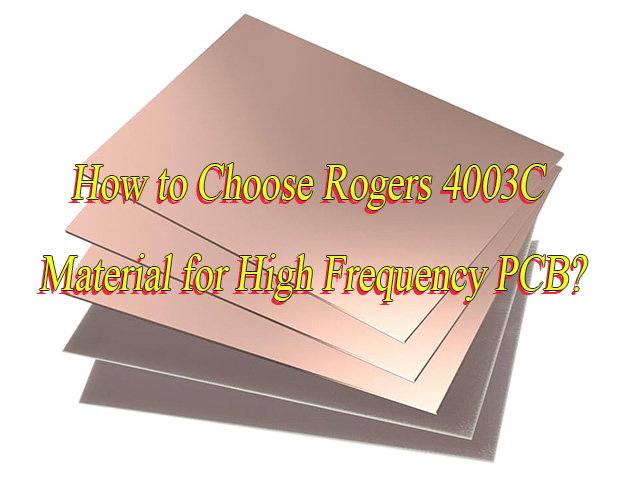
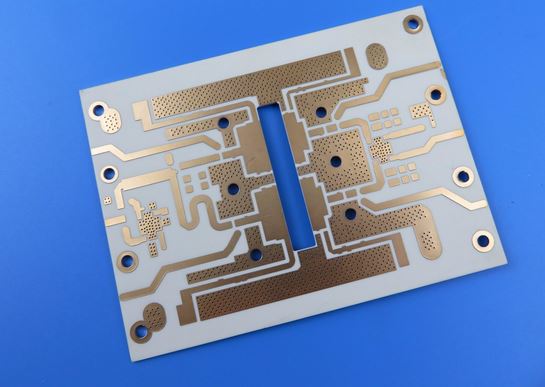
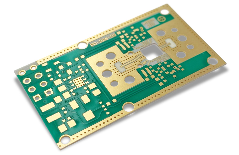
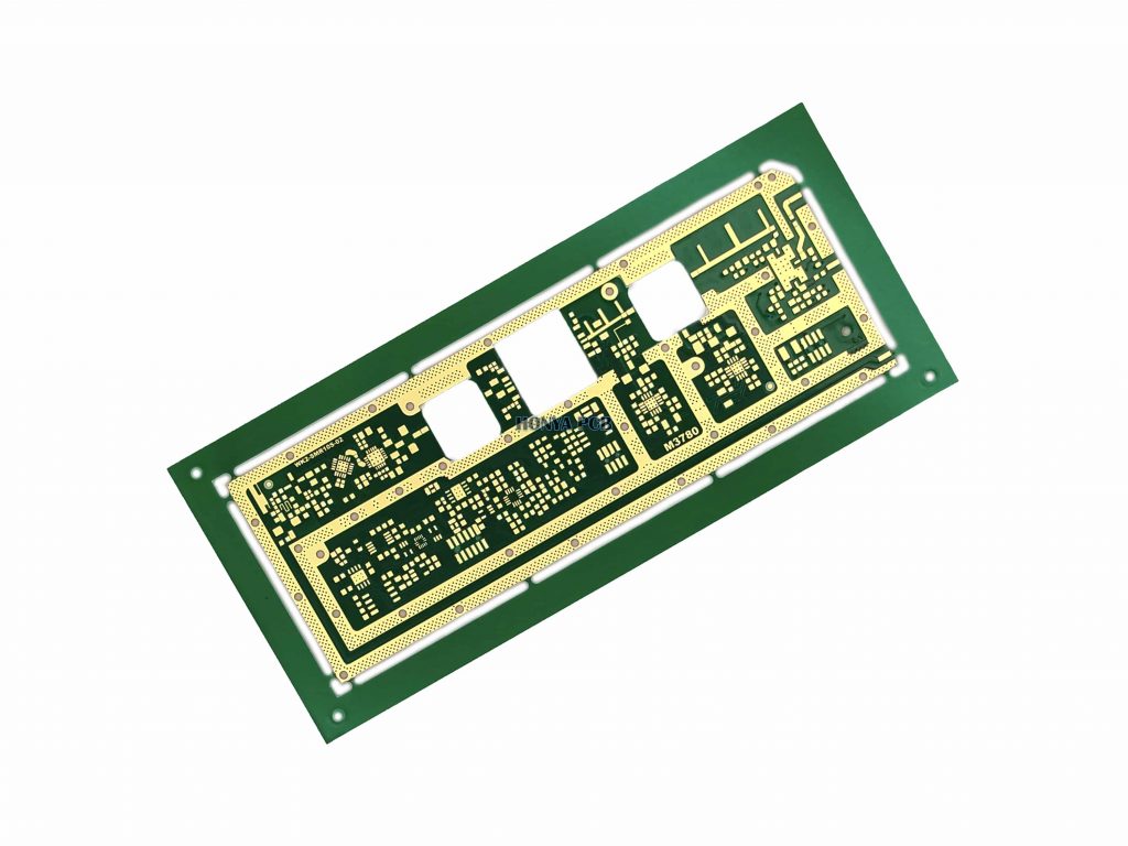
Why choose Rogers 4003C for high frequency PCB? Let’s discover Rogers 4300C’s benefits, application, datasheet and cost, difference between 4350B.
Are you troubled with these problems?
- Struggling with high-frequency signal loss control?
- Worried about inconsistent dielectric constants affecting performance?
- Concerned about delamination or warping during processing lowering yield rates?
EBest Circuit (Best Technology) can provide you solutions:
- 30% loss reduction with specialized low-loss substrates, cleaner signals, faster designs.
- ±2% dielectric constant stability through proprietary stabilization tech, consistent performance, every time.
- Process-friendly custom materials that align with mainstream lamination processes, 50% lower delamination risk, smoother mass production.
Welcome to contact us if you have any request for Rogers 4003C materials: sales@bestpcbs.com.
What Is Rogers 4003C Material?
Rogers 4003C is a high-performance high-frequency circuit board substrate (laminate) produced by Rogers Corporation, belonging to its RO4000® series. It is composed of ceramic-filled hydrocarbon resin and glass fiber reinforced materials. Main Features include a stable dielectric constant of approximately 3.38 at 10 GHz, an extremely low loss factor of about 0.0027 at 10 GHz, and a thermal expansion coefficient matched to copper foil (X/Y axis approximately 11 ppm/°C).
It is specifically designed for RF/microwave/millimeter-wave applications requiring low signal loss and high reliability, such as base station antennas, automotive radar, and satellite communications. Additionally, it offers processing advantages similar to standard FR-4 materials.

Rogers 4003C Datasheet
| Parameter Name | Value + Unit |
| Dielectric Constant (Dk) | 3.38 ± 0.05 |
| Loss Factor (Df) | 0.0027 |
| Z-axis Coefficient of Thermal Expansion (CTE) | 46 ppm/°C |
| Glass Transition Temperature (Tg) | ï¼280 °C |
| Thickness Range | 0.203-1.524 mm |
| Processing Technology | Compatible with FR-4 |
| Flame Retardancy Rating | Not Compliant with UL 94 V-0 |
| Application Fields | Base Station Antennas / Automotive Radar / Satellite Communications |
| Thermal Conductivity | 0.6-0.8 W/(m·K) |
| Surface Treatment | Immersion Gold / OSP (Organic Solderability Preservative) |
| Minimum Trace Width/Spacing | 3mil/3mil |
| Minimum Hole Diameter | 4 mil |
| Maximum Panel Size | 540Ã1200 mm |
| Impedance Control Tolerance | ±8% |
Applications of Rogers 4003C Material
- 5G base station antenna PCBs
- Satellite navigation equipment
- Automotive millimeter-wave radar
- Aerospace precision circuits
- Medical and IoT devices
- Microwave communications and power amplifiers
- Industrial automation PCBs
- Radar and RFID systems
- Extreme environment circuits
- Multi-layer high-frequency PCB design
What Is the Difference between Rogers 4003C and 4350B?
Material Composition:
- Rogers 4003C: Ceramic-filled hydrocarbon laminate with silica (SiOâ) ceramic particles composite polyolefin matrix. Halogen-free formula compliant with RoHS/REACH environmental standards. Surface treatment typically uses sodium etching to enhance copper adhesion.
- Rogers 4350B: Glass fiber reinforced hydrocarbon matrix using E-glass or low-dielectric constant glass cloth. Contains trace halogen components (e.g., brominated flame retardants). Compatible with FR4 processes, supporting conventional chemical copper plating and pattern plating.
Dielectric Constant (Dk):
- Rogers 4003C: Nominal Dk=3.38±0.05 (tested at 1GHz), recommended design value 3.55 (accounting for frequency drift compensation). Stability within ±1% at 10GHz, suitable for millimeter-wave bands (e.g., 28GHz/39GHz) for precise impedance control.
- Rogers 4350B: Nominal Dk=3.48±0.05 (tested at 1GHz), recommended design value 3.66 (including process tolerance). Low Dk variation with temperature, ideal for wide-temperature operation (-55â~125â).
Loss Factor (Df):
- Rogers 4003C: Typical Df=0.0021@1GHz, 0.0027@10GHz. Dielectric loss tangent (Tanδ) as low as 0.0004 at high frequencies. Signal attenuation coefficient (α) 15%-20% lower than 4350B, suitable for ultra-low loss requirements like satellite communication payloads.
- Rogers 4350B: Typical Df=0.0031@1GHz, 0.0037@10GHz. Tanδ=0.0006 at high frequencies. Slightly higher loss but cost-effective, suitable for medium-power scenarios like automotive radar (77GHz) mass production.
Thermal Performance:
- Rogers 4003C: X/Y-axis CTEâ4-6ppm/â, Z-axis CTEâ30-40ppm/â. Thermal conductivityâ0.6W/(m·K). Excellent dimensional stability, multi-layer alignment accuracy â¤Â±25μm, ideal for high-precision RF modules.
- Rogers 4350B: X/Y-axis CTEâ10-12ppm/â, Z-axis CTEâ50-60ppm/â. Thermal conductivityâ0.8W/(m·K). Superior thermal performance in high-power scenarios, but Z-axis expansion requires attention to via reliability.
Mechanical Strength and Processability:
- Rogers 4003C: Flexural strength â¥270MPa, outstanding fatigue resistance for vibration environments (e.g., aerospace). Drilling parameters require control (e.g., spindle speed â¤20krpm, feed rate â¤0.8m/min) to avoid substrate cracking.
- Rogers 4350B: Flexural strength â¥240MPa. FR4-compatible processes (e.g., mechanical drilling, plasma etching). Supports automated assembly lines, but glass cloth texture may affect microstrip edge roughness.
Thickness Range:
- Rogers 4003C: Standard thickness from 0.008 inch (0.203mm) to 0.060 inch (1.524mm). Ultra-thin 0.004 inch (0.101mm) requires customization. Thickness tolerance ±3%.
- Rogers 4350B: Conventional thickness from 0.004 inch (0.101mm) to 0.060 inch (1.524mm). Offers prepreg options, supporting thin laminate structures (e.g., 0.002 inch stack) for compact designs.
Application Scenarios:
- Rogers 4003C: High-frequency communication base stations (e.g., 5G macrocells), phased array antennas, low-noise amplifier (LNA) modules, precision test fixtures. Ideal for scenarios demanding stringent signal integrity.
- Rogers 4350B: Automotive ADAS radar (24GHz/77GHz), military radar systems, high-power RF front-ends (e.g., power amplifiers), consumer wireless devices (e.g., Wi-Fi6/6E routers). Balances cost and performance.
Cost and Environmental Compliance:
- Rogers 4350B: Unit area cost 15%-30% lower than 4003C. Suitable for large-scale production projects. Contains trace halogens, requiring attention to terminal product environmental certifications.
- Rogers 4003C: Halogen-free formula certified by UL, compliant with EU ELV directives. Suitable for medical, rail transportation, and other fields with mandatory environmental requirements. Higher unit price requires budget consideration.
How Much Does Rogers 4003C Cost?
The price range for Rogers 4003C high-frequency PCB material is influenced by multiple factors, including thickness, number of layers, surface treatment, and order volume. Market research shows that single-sheet prices range from $2.99 ââto $8.99 (e.g., 60-mil thick double-sided boards), and $20 to $30 (including surface treatments such as immersion gold/silver/tin).
The prototype cost of a multi-layer board (e.g., a 4-layer board) is approximately $150 to $320, and the price per square foot is approximately $7 to $12 per square foot. Price fluctuations are also related to material specifications (e.g., 8-mil to 60-mil thickness), process complexity (e.g., blind and buried vias, resin plugged vias), and exchange rate fluctuations. Asian suppliers (e.g., China) generally offer more competitive prices due to their production volume advantages, while North American/European suppliers may impose higher costs due to certification standards (e.g., MIL-SPEC) or small-volume orders.

Why Choose Rogers 4003C for High Frequency PCB?
Reasons why choose Rogers 4003C Material for High Frequency PCB:
- Signal stability: Dk = 3.38 ± 0.05 (10 GHz), Df = 0.0027, low attenuation in millimeter-wave communications, and faster and more accurate data transmission.
- Environmental durability: Z-axis thermal expansion of 46 ppm/°C with copper foil, Tg > 280°C, no warping in deserts and polar regions, minimal failures, and long lifespan.
- Cost-effectiveness: FR-4-compatible process eliminates special processing, reducing costs by over 30%, making it suitable for mass production.
- Application adaptability: Stable above 10 GHz, suitable for radar, base stations, automotive radar, RFID, and other applications, improving recognition accuracy.
- Long-term stability: High strength, low crack resistance, low water absorption, stable in humid and hot environments, and low maintenance and risk.

How to Choose Rogers 4003C Material for High Frequency PCB?
Rogers 4003C High-Frequency PCB Material Selection Guide
1. Electrical Performance Advantages
- Dielectric constant (Dk) stabilized at 3.38±0.05 (10GHz) with minimal frequency fluctuation, ensuring precise signal transmission.
- Low loss tangent (Df) of 0.0027 (10GHz), significantly lower than traditional FR4 materials, reducing high-frequency signal transmission loss.
- Suitable for high-frequency scenarios such as 5G millimeter-wave, radar systems, and high-speed data transmission.
2. Thermal Stability and Mechanical Reliability
- Z-axis coefficient of thermal expansion (CTE) of 46ppm/â matches copper foil, reducing risks of delamination and warpage under temperature changes.
- Glass transition temperature (Tg) exceeding 280°C supports lead-free soldering processes, ensuring dimensional stability in extreme thermal environments.
3. Processing Compatibility
- Compatible with conventional FR4 epoxy/glass cloth processing techniques, eliminating the need for specialized treatments like plasma etching or PTFE material through-hole processing.
- Supports standard PCB production processes such as solder mask grinding, plated through-holes, and fine-line circuit fabrication.
4. High-Frequency Application Scenarios
- Widely used in automotive radar (77GHz/24GHz), 5G base station antennas, satellite communication, RFID, microwave power amplifiers, and other high-frequency applications.
- Particularly suitable for millimeter-wave bands (e.g., 67GHz projects) due to low loss characteristics, ensuring stable signal coverage and high-speed data transmission.
5. Cost Efficiency and Alternative Solutions
- Cost-effective compared to traditional microwave laminates (e.g., PTFE-based materials), offering superior performance-to-cost ratio.
- For safety-critical applications requiring UL 94V-0 flammability ratings, alternatives like RO4835™ or RO4350B™ can be considered.
6. Material Characteristic Comparison
- Outperforms FR4 in dielectric constant stability, high-frequency loss control, and thermal expansion matching.
- Compared to RO4350B™, RO4003C exhibits lower loss (0.0027 vs. 0.0037), making it ideal for gain-sensitive systems.
7. Design Considerations
- Attention to moisture absorption rate (0.06%) impacting long-term reliability.
- Optimization of transmission line structures (e.g., grounded coplanar waveguides) and simulation verification for circuit performance.

Why Choose EBest Circuit (Best Technology) as High Frequency PCB Manufacturer?
Reasons why choose us as high frequency PCB manufacturer:
- Two Decades of High-Frequency PCB Expertise: With 20 years of specialization in high-frequency PCB manufacturing, has delivered over 10,000 high-end projects including 5G base station antennas, automotive radars, and satellite communication modules. Masters cutting-edge technologies such as 0.004-inch ultra-thin panel processing and HDI (High Density Interconnect).
- Authoritative Certifications Backing Strength: Holds concurrent certifications including ISO 9001 (Quality Management), ISO 14001 (Environmental Management), UL Safety Certification, and AEC-Q200 (Automotive Grade), satisfying stringent compliance requirements across automotive, medical, military, and other sectors.
- Top-Tier Material Quality Assurance: Selects premium high-frequency substrates like Rogers 4003C/4350B, combined with ceramic-filled hydrocarbon technology, achieving dielectric constant fluctuation â¤Â±0.05 (at 10GHz) and ultra-low loss tangent of 0.0027, ensuring zero signal attenuation for 5G millimeter-wave, radar systems, and other high-frequency scenarios.
- Cost Advantage Breaking Industry Bottom Line: Reduces costs by 30% through scaled procurement and automated production line optimization, with unit area costs 15-20% below industry average. For million-unit orders, prices drop by 25%, empowering clients to seize market opportunities ahead of competitors.
- Industry-Leading Rapid Delivery: Offers 7-day rapid prototyping service and compresses mass production lead time to 15-20 days (40% shorter than industry average). Equipped with intelligent production scheduling system for 24/7 real-time order tracking, ensuring urgent projects like 5G base station antennas are delivered 3-5 days earlier to capture market windows.
- Full-Cycle Customization Services: Provides end-to-end solutions from DFM design support to final testing, supported by on-site senior engineering teams to resolve impedance matching and thermal management challenges. Accommodates specialized processes including blind/buried vias and resin plugging.
- Strict Quality Control System: Implements triple-layer quality assurance via AOI optical inspection, flying probe testing, and X-ray laminography, achieving >99.2% yield. Each batch undergoes 288°C solder float test (IPC-TM-650), 1,000-hour 85°C/85%RH humidity aging test, and -55°C to 150°C thermal cycling, meeting aerospace-grade reliability for defect-free delivery.
Welcome to contact us if you have any request for high frequency circuit board: sales@bestpcbs.com.


