

When designing RF and microwave PCBs, the laminate you choose directly affects insertion loss, impedance consistency, manufacturability, and long-term reliability. Among the many high-frequency materials from Rogers Corporation, RO4003C and RO4350B remain two of the most commonly used options across wireless, radar, and high-power RF hardware.
So, what is difference between RO4003C and RO4350B? Maybe you can find answer here. This guide breaks down how the two materials differ, how they perform electrically, what thickness options are available, and which material fits specific RF applications.
What Is Rogers RO4003C?
RO4003C is a glass-reinforced hydrocarbon ceramic laminate designed as a middle-ground option between standard FR-4 and more advanced microwave substrates. It was formulated to deliver excellent RF performance without the processing complexities associated with PTFE-based materials. Because its fabrication requirements align closely with FR-4, it has become a go-to material for mid-frequency wireless modules requiring predictable performance at a reasonable cost.
Material Composition
- Hydrocarbon/ceramic-filled resin system
- Woven glass reinforcement
- PTFE-free formulation
- Compatible with mainstream FR-4 manufacturing flows
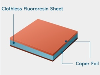
This combination makes RO4003C easier to fabricate, more dimensionally stable, and more economical for medium-frequency applications, while still achieving significantly lower loss than FR-4.
Strengths
- Lower insertion loss than FR-4, particularly above 2 GHz
- Stable dielectric constant (~3.38) across temperature and frequency
- No need for PTFE-type specialized drilling or etching
- Widely available in multiple thicknesses and copper weights
- Highly cost-effective for mid-range RF and mixed-signal applications
Limitations
- Higher loss than RO4350B under high-power or high-frequency conditions
- Somewhat reduced thermal reliability compared with RO4350B
- Standard RO4003C does not carry a UL94 V-0 flame rating (except LoPro variants)
Best Suited For
RO4003C is ideal when you need solid RF performance without the cost or processing requirements of higher-end laminates:
- 2.4–10 GHz RF signal chains
- IoT radios, compact wireless modules
- Patch antennas, printed antennas, and small radar systems
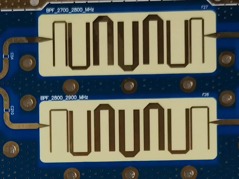
- LNAs, mixers, filters, RF front-end circuits
Its combination of affordability, consistency, and manufacturability has made it a staple material for mainstream RF electronics.
What Is RO4350B Material?
RO4350B is a flame-retardant hydrocarbon ceramic laminate engineered for high power, high reliability, and high-frequency RF systems. It delivers tighter dielectric control and improved thermal behavior compared with RO4003C.
Key Properties
- Dk ≈ 3.48 (slightly higher than RO4003C)
- Df ≈ 0.0037, supporting lower insertion loss at high power
- UL94 V-0 flame-retardant rated
- Higher thermal conductivity
- Very tight Dk tolerance for precision RF designs
- Higher Tg, improving stability during soldering and high-temp processing
Typical Use Cases
- High-power RF amplifiers
- 5G, LTE, and small-cell base stations
- Automotive radar (24 / 77 GHz)
- Satellite and aerospace RF systems
- Filters, couplers, and phased-array modules
RO4350B is ideal when electrical performance and thermal robustness are both critical.
RO4003C vs RO4350B: Electrical Performance Comparison
Although both materials belong to the same hydrocarbon ceramic family, their microwave performance differs in several meaningful ways.
| Property | RO4003C | RO4350B | Notes |
| Dielectric Constant (Dk) | ~3.38 | ~3.48 | Higher Dk allows slightly smaller RF structures |
| Dissipation Factor (Df) | ~0.0027 | ~0.0037 | RO4350B performs better at high power; RO4003C wins at lower GHz |
| Thermal Conductivity | Lower | Higher | RO4350B dissipates heat more effectively |
| Temperature Stability | Good | Excellent | RO4350B is more stable outdoors and under load |
| Power Handling | Medium | High | RO4350B excels in power electronics |
| Insertion Loss | Good | Better | Particularly for long feedlines or high-power paths |
Summary
- RO4003C → balanced, economical, suitable for mid-frequency designs
- RO4350B → precision-grade material designed for high power and extreme stability
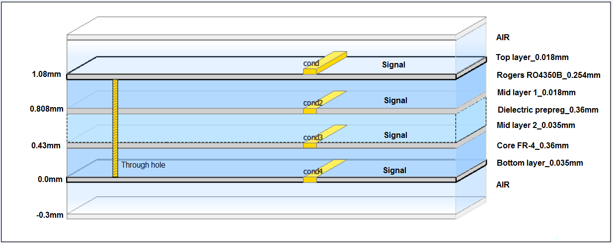
RO4003C vs RO4350B: Thickness Options
Both laminates are available in a wide range of core thicknesses. However, their catalogs differ slightly, and RO4350B generally has tighter tolerances—important for controlled-impedance designs.
Common RO4003C Thicknesses
- 0.101 mm
- 0.203 mm
- 0.304 mm
- 0.508 mm
- 0.813 mm
- 1.524 mm
These options cover almost all mainstream antenna, filter, and RF routing needs.
Common RO4350B Thicknesses
- 0.101 mm
- 0.168 mm
- 0.254 mm
- 0.508 mm
- 0.762 mm
- 1.524 mm
RO4350B’s tighter thickness control results in more consistent RF behavior, especially in multi-layer microwave structures.
Is RO4003C Really Cheaper Than RO4350B?
In most real-world PCB quotations, RO4003C is indeed 10–25% cheaper than RO4350B. Yet the difference is not as large as engineers sometimes expect. RO4003C is less expensive because its resin does not include flame-retardant chemistry, its Dk tolerance is more forgiving, and its manufacturing process closely resembles FR-4. These factors reduce both the material price and the cost of PCB fabrication.
RO4350B’s higher cost comes from its UL94 V-0 rating, tighter dielectric tolerance, more stable thermal behavior, and more complex resin formulation. These advantages are essential in automotive radar, 5G systems, and aerospace electronics, where reliability and compliance requirements outweigh material cost. In small prototype runs, the price difference may be overshadowed by drill-time cost, impedance testing, or engineering setup fees. Therefore, while RO4003C is typically cheaper, the decision should still be guided by system-level performance rather than material cost alone.
When to Choose RO4003C and When to Choose RO4350B?
Selecting between the two laminates depends on frequency, power, environmental conditions, and regulatory constraints.
Choose RO4003C When:
- operating frequency is below ~10 GHz
- cost efficiency is a primary goal
- fabrication simplicity is desired
- power levels are moderate
- the application is IoT, Wi-Fi/Bluetooth, radar front ends, or compact RF modules
Choose RO4350B When:
- high power must be handled safely
- stringent Dk tolerance is required
- UL94 V-0 flame resistance is mandatory
- operating frequency spans 10–40+ GHz
- the application involves radar, satellite links, aerospace RF, or 5G infrastructure
RO4003C is best for mid-range systems, while RO4350B excels in harsh or precision-critical environments.
Key Fabrication Notes for RO4003C and RO4350B PCBs
- tightly control dielectric thickness during lamination
- ensure copper etching tolerance remains consistent for impedance control
- use plasma cleaning to improve hole-wall quality
- low-profile copper improves loss performance
- avoid excessive lamination temperatures to protect resin integrity
- select solder mask materials that do not absorb RF energy
Manufacturers experienced with Rogers laminates can reduce variability and ensure RF performance matches the design model.
RO4003C vs RO4350B vs FR4: Is Rogers Always Necessary?
FR-4 still plays an important role in RF design, especially where frequency demands are low and cost is a major constraint.
FR-4 Is Acceptable For:
- sub-1 GHz circuits
- low-precision RF systems
- consumer electronics
Rogers Materials Are Required When:
- insertion loss must be minimized
- impedance variation must remain within ±5–10%
- thermal stability is essential
- high power or high frequency is involved
- mmWave operation (24–77 GHz) is required
Quick Comparison
| Material | Frequency Range | Loss | Cost | Best Applications |
| FR-4 | <1 GHz | High | $ | Basic RF |
| RO4003C | 1–10 GHz | Medium-low | $$ | Antennas, IoT, radar |
| RO4350B | 10–40+ GHz | Low | $$$ | 5G, radar, high-power RF |
FAQs About RO4003C and RO4350B
1. Can RO4003C replace RO4350B?
Yes, for sub-10 GHz and moderate-power designs, RO4003C can often replace RO4350B with minimal impact on performance.
2. Is RO4350B flame-retardant?
Absolutely. It is UL94 V-0 certified and widely accepted for telecom and aerospace hardware.
3. Which material has lower loss?
RO4350B generally performs better, especially in long RF traces or high-power paths.
4. Can FR-4 and Rogers be mixed in the same stackup?
Yes. Hybrid stackups are common in RF modules to balance cost and performance.
5. Which is better for antennas?
RO4003C suits most mid-frequency antennas; RO4350B is superior for high-power or outdoor antennas.
6. Which is better for 5G base stations?
RO4350B, due to its exceptional dielectric stability and flame resistance.
7. Do both support multilayer RF PCB structures?
Yes—with proper process control and experienced fabrication.
8. Are both suitable for mmWave?
RO4350B is the preferred option due to its lower loss and tighter tolerance.
9. Do they require special plating?
Standard plating works, but IPC-4103 guidelines are recommended for consistency.