

MMCX PCB is the backbone of modern miniaturized radio frequency (RF) modules, providing the critical interface for high-frequency signal transmission in extremely limited spaces. This comprehensive guide explores everything from connector selection and design best practices to manufacturing advantages, equipping you to master custom MMCX PCB design for your compact wireless devices.
Do you struggle to balance performance, size, and reliability in your mini RF modules? You’re not alone. Designing with MMCX PCB connectors presents unique challenges:
- Signal degradation from impedance mismatches.
- Mechanical failure due to poor connector choice or board mounting.
- Complex layout constraints in high-density designs.
- Difficulty sourcing reliable, high-quality MMCX PCB.
- Managing costs while meeting stringent RF performance specs.
The good news is that these challenges have proven solutions. By focusing on a few key areas, you can achieve robust and high-performing designs.
- Precise impedance control calculations and simulation prevent signal issues.
- Selecting the correct MMCX PCB mount connector type ensures mechanical stability.
- Adhering to RF-optimized layout rules overcomes space constraints.
- Partnering with an experienced RF MMCX PCB manufacturer guarantees component quality.
- Optimizing the design for manufacturability from the start controls costs.
At BEST Technology, we specialize in best possible high-frequency PCB solutions. Our great technical expertise ensures your custom MMCX PCB design is built with rigorous quality control, superior materials, and rapid turnaround. Pls feel free to contact us at sales@bestpcbs.com to bring your mini RF module to the real life.
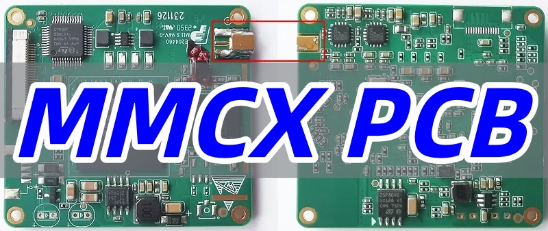
What Is an MMCX PCB?
An MMCX PCB integrates Micro-Miniature Coaxial (MMCX) connectors directly onto a printed circuit board, creating essential RF interfaces for compact wireless devices. This configuration is particularly valuable for space-constrained applications where reliable high-frequency connections are critical.
Key Characteristics:
- Miniaturization: MMCX connectors are significantly smaller than traditional RF connectors like SMA, making them ideal for modern compact electronics.
- Board-Level Integration: These connectors are designed specifically for PCB mounting, providing a permanent and robust RF interface solution.
- High-Frequency Capability: Properly designed MMCX PCBs maintain signal integrity at frequencies up to 6 GHz, suitable for most wireless applications.
The effectiveness of an MMCX PCB design hinges on maintaining precise impedance control and ensuring a seamless transition from the connector to the PCB’s transmission lines.
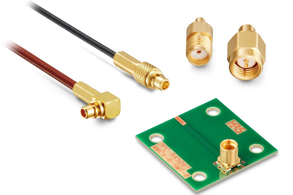
Types of MMCX PCB Connectors Used Today
Selecting the appropriate MMCX connector type is fundamental to achieving both optimal electrical performance and mechanical stability in your design.
Primary Connector Variants:
- By Orientation:
- Vertical Mount: Standard orientation for straightforward vertical cable connection
- Right-Angle Mount (MMCX R PCB): Ideal when cable routing parallel to the board surface is preferred
- By Gender Configuration:
- Standard Gender: Conventional male/female pairing
- Reverse Polarity (MMCX LR PCB): Gender-reversed versions used for specific compatibility requirements
- By Mounting Style:
- Surface Mount (SMD): Preferred for automated assembly and space-constrained designs
- Through-Hole: Offers enhanced mechanical strength for high-vibration environments
Understanding these options enables designers to select the most suitable MMCX PCB connector for their specific application requirements.
How to Choose the Right MMCX PCB Mount Connector?
Selecting the optimal connector requires careful consideration of multiple technical and practical factors.
Selection Criteria:
- Performance Requirements:
- Frequency range and insertion loss specifications
- Impedance matching (typically 50Ω) and VSWR requirements
- Mechanical Considerations:
- Expected mating cycles and durability needs
- Board space constraints and height restrictions
- Cable exit direction and strain relief requirements
- Manufacturing Factors:
- Compatibility with automated assembly processes
- Soldering temperature tolerance and thermal mass
A systematic evaluation against these criteria ensures the selected MMCX PCB mount connector will meet both performance and reliability targets.
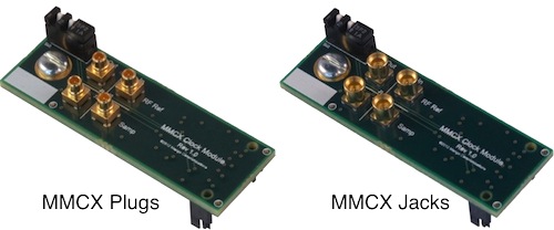
MMCX Male PCB vs MMCX Female PCB Differences
Selecting the correct connector gender for PCB mounting is critical for both mechanical integrity and electrical performance in RF designs. The primary differences lie in their physical structure, typical applications, and design implications.
1. Physical Structure and Interface
- MMCX Female PCB Connector (Jack):
This component features an internal receptacle with a slotted, spring-loaded center contact.
It is the standard interface soldered onto the board.
The MMCX female PCB connector is designed to accept and grip the male pin, providing a secure and reliable connection. - MMCX Male PCB Connector (Plug):
This type has a central pin that extends from the connector body.
The MMCX male PCB is inserted into the female jack, and the connection is maintained by the jack’s internal spring mechanism.
2. Typical Applications and Usage
- Standard Board-Level Interface (Female Jack):
The MMCX female connector PCB mount is the predominant choice for the fixed connection point on a circuit board.
It is used for connecting to antenna cables, external modules, or test equipment.
Its design protects the central mating interface from physical damage. - Specialized Applications (Male Plug):
The MMCX male PCB connector is less common. Its typical uses include:- Board-to-Board Interconnects: Directly connecting two PCBs in a stacked or coplanar configuration.
- Adapter Boards: Functioning as an MMCX PCB adapter on a small circuit board to convert interfaces.
- Specific Cable Exit Requirements: Used when a particular mechanical layout demands a male connector on the board itself.
3. Design and Sourcing Considerations
- Mechanical Reliability:
The female jack, once soldered to the PCB, generally offers better resistance to mechanical stress because its sensitive internal parts are housed and protected.
The protruding pin of a male connector is more susceptible to bending or damage. - Polarity and System Planning:
Using a standard MMCX female PCB jack simplifies system design, as most cables are terminated with male plugs.
Employing a male connector on the board requires careful planning to ensure cable and interoperability. - Supply Chain Simplification:
The MMCX female PCB connector is a standard, widely available component.
Opting for this standard streamlines sourcing and reduces compatibility risks compared to the less common male-board-mount variant.
In summary, for most designs where the PCB serves as the fixed base for a removable cable, the MMCX female PCB connector is the recommended and conventional choice. The MMCX male PCB connector is reserved for specific, specialized interconnect scenarios.
MMCX PCB Jack Design Points for RF Stability
Achieving RF stability requires meticulous attention to both component selection and layout implementation.
Critical Design Considerations:
- Footprint Accuracy:
- Strict adherence to manufacturer-recommended land patterns
- Proper pad dimensions and spacing for reliable soldering
- Impedance Continuity:
- Smooth transition from connector pin to transmission line
- Controlled trace width matching the system impedance (50Ω)
- Grounding Implementation:
- Continuous ground plane beneath the connector
- Strategic via placement for effective RF return paths
Proper implementation of these design principles ensures the MMCX PCB jack maintains signal integrity across the required frequency spectrum.
How MMCX PCB Adapter and MMCX Pigtail Improve Routing?
MMCX PCB adapters and pigtails offer distinct and complementary solutions for overcoming spatial and mechanical challenges in compact RF module design. They enhance flexibility, reliability, and performance by redefining the connection point between the PCB and the external RF world.
1. MMCX PCB Adapter:
An MMCX PCB adapter is a board-mounted component that provides a permanent interface conversion.
- Function: It acts as a standardized port on your PCB, typically converting the MMCX interface larger, more common type like SMA.
- Routing & Design Improvement:
- Saves Space: Allows the use of a tiny MMCX footprint on the PCB while enabling connection to standard test equipment cables without a dedicated, space-consuming SMA connector.
- Facilitates Testing: Provides a robust, dedicated point for connecting test equipment (e.g., vector network analyzers) during development and debugging, preventing damage to fragile direct solder points.
- Design Reusability: A single PCB design can be adapted for different external connectivity needs simply by changing the onboard adapter.
2. MMCX Pigtail:
An MMCX pigtail is a short, flexible cable with a pre-attached connector.
- Function: It creates a short, shielded RF bridge between the PCB and a component like an antenna.
- Routing & Design Improvement:
- Decouples Component Placement: It physically separates the antenna or sensor from the main PCB, allowing it to be positioned optimally for performance (e.g., away from interference, near a housing window) without being constrained by the PCB’s location.
- Absorbs Stress: The flexible cable absorbs strain, vibration, and torsion that would otherwise transfer directly to the solder joints of a board-mounted connector, significantly improving mechanical reliability and long-term durability.
- Simplifies Assembly: Enables modular assembly, where the PCB and antenna can be installed separately and connected last, streamlining the manufacturing process.
Summary:
| Component | Solves This Problem | Primary Benefit |
|---|---|---|
| MMCX PCB Adapter | Interface incompatibility and need for test points | Protocol Conversion on the board itself. |
| MMCX Pigtail | Physical layout constraints and mechanical stress | Spatial Flexibility and Strain Relief. |
In practice, these components are often used together. For example, a PCB might feature an MMCX PCB adapter for external connectivity, while an internal MMCX pigtail connects to an antenna mounted elsewhere inside the device. This combination delivers maximum routing flexibility and reliability for custom MMCX PCB designs in mini RF modules.
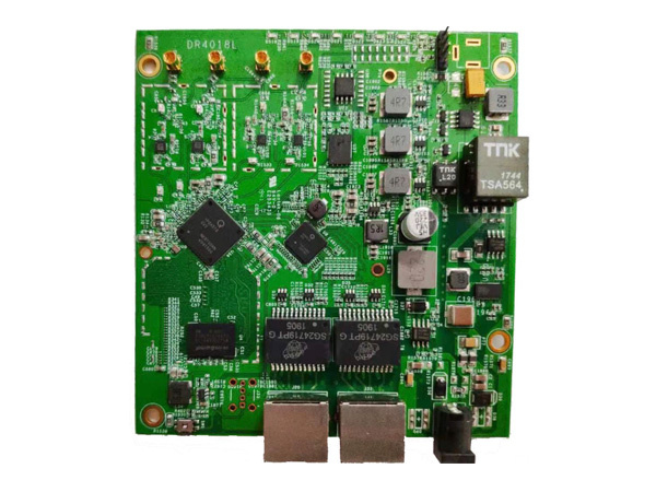
China RF MMCX PCB Manufacturing Advantages
Partnering with specialized manufacturers offers distinct benefits for producing high-quality RF circuits.
Key Advantages:
- Technical Expertise:
- Extensive experience with high-frequency materials (Rogers, Taconic)
- Sophisticated impedance control capabilities (±5% or better)
- Economic Benefits:
- Competitive pricing without compromising quality
- Efficient supply chain management reducing lead times
- Comprehensive Support:
- Design for manufacturability (DFM) feedback
- Rapid prototyping and volume production flexibility
These advantages make partnering with a specialized RF MMCX PCB manufacturer a strategic choice for developing high-performance wireless modules.
How to Request RF MMCX PCB Quotes from a Factory?
Obtaining accurate quotations requires providing comprehensive project information.
Essential Documentation:
- Technical Specifications:
- Complete Gerber files with all layer stack-up details
- Detailed bill of materials (BOM) with component specifications
- Requirements Definition:
- Quantities needed (prototype vs. production volumes)
- Impedance control requirements and testing criteria
- Required delivery timeline and quality expectations
Providing clear, complete information enables manufacturers to generate accurate RF MMCX PCB quotes and identify potential production issues early in the process.
MMCX PCB is well-suited for compact medical electronics, delivering stable RF performance in space-limited designs. They are frequently integrated into devices such as portable patient monitors and pulse oximeters due to their reliable signal transmission. With ISO 13485 certification, EBest Circuit (Best Technology) supports full-process MMCX PCB manufacturing and SMT MMCX PCB assembly services. If you have a project to discuss, feel free to submit your requirements through the contact form on our Contact Us page.
Ultimately, an MMCX PCB is a precision component that forms the reliable RF link in today’s miniaturized wireless electronics. Mastering its design, from connector selection to layout and manufacturing partnership, is key to module success. BEST Technology combines engineering expertise with stringent quality control to deliver high-performance custom MMCX PCB solutions that meet your specifications and timeline. For your next mini RF module project, pls feel free to contact our team at sales@bestpcbs.com for a consultation and quote.